Mesh-induced elastic anisotropy and distorting the quad. points as a way to palliate it

David F

Bruno Turcksin

Wolfgang Bangerth
>
> *_Q2_:* why the system behaves as anisotropic if its local inhomogeneous
> the problem of mesh-induced elastic anistropy in FEM, I would like to know it.
layers of isotropic materials, then you get an anisotropic material. Think
about layering styrofoam plates with steel plates -- the resulting stack of
layers is essentially incompressible under loads from the side (because the
steel plates provide the stiffness), but is quite compressible if you load it
from top and bottom (because the styrofoam layers will simply collapse).
Best
W.
--
------------------------------------------------------------------------
Wolfgang Bangerth email: bang...@colostate.edu
www: http://www.math.colostate.edu/~bangerth/
David F
Wolfgang Bangerth
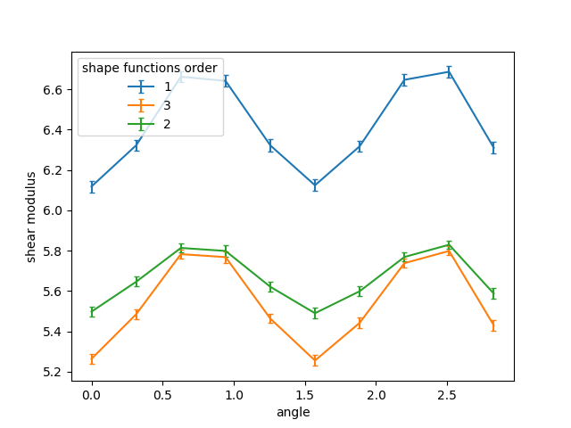
> I have a 2D system for which I create the stiffness tensor of an isotropic
> material, but for each finite element I create it with a different shear
> modulus. The shear modulus is random for each element (I use an exponential
> distribution, but any distribution leads to the same behavior as long as the
> std is high), with no structure such as layers or anything else. In this case,
> the system should clearly be macroscopically isotropic (up to statistical
> fluctuations due to the random properties) for symmetry reasons.
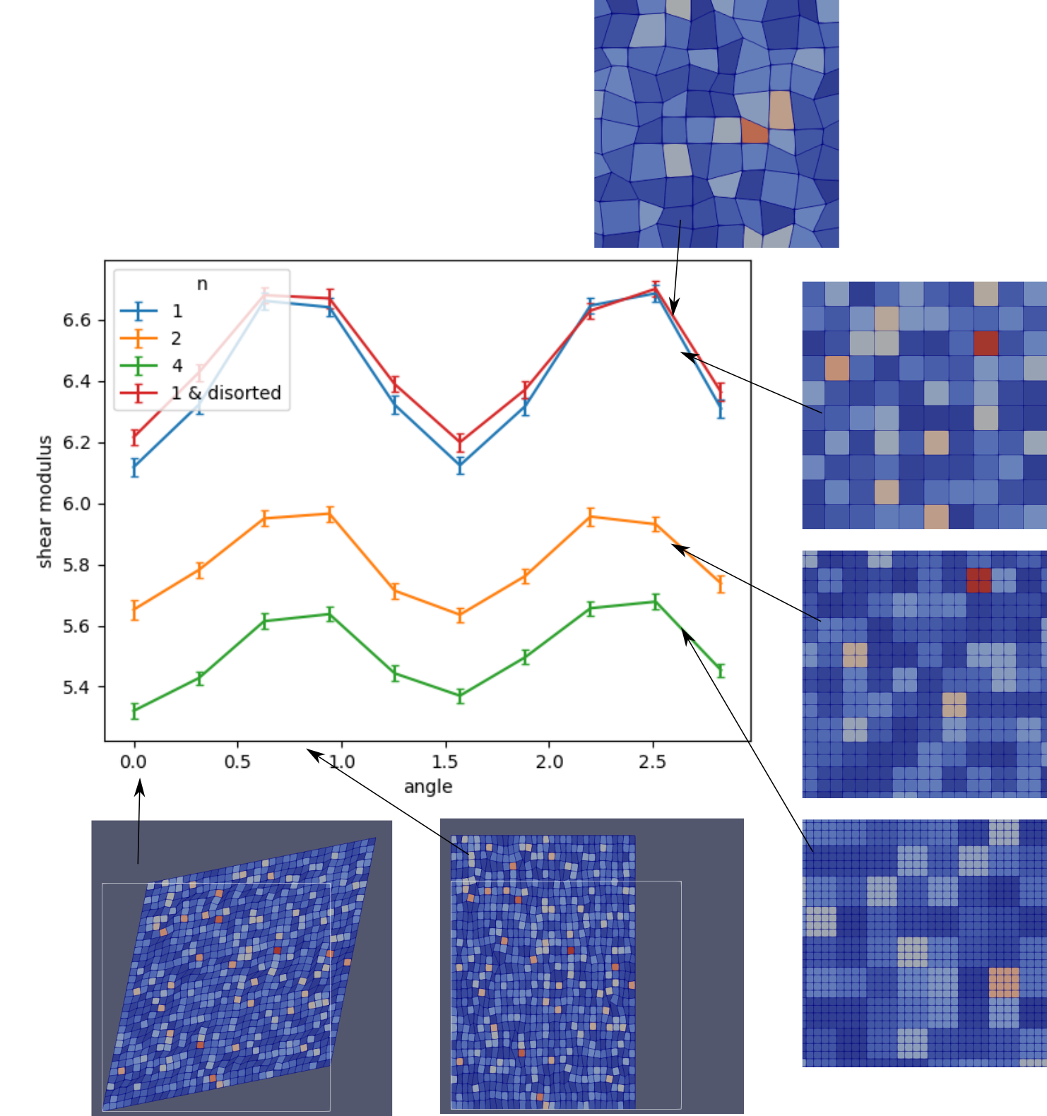
the material has a degree of anisotropy that goes to zero as you make the mesh
smaller. It is true that the axes of anisotropy should be oriented in random
ways for different realizations of the same experiment on the same mesh. When
you do your computations, have you checked (for different realizations of the
random process):
(i) whether the orientation of anisotropy is always the same, and always
related to the principal directions of the mesh?
(ii) how the magnitude of anisotropy behaves as you refine the mesh?
David F
David F

Sebastian Stark
Hi David,
I'm neither an expert, nor do I know the literature well, but
looking on your pictures, I think, the situations you are studying
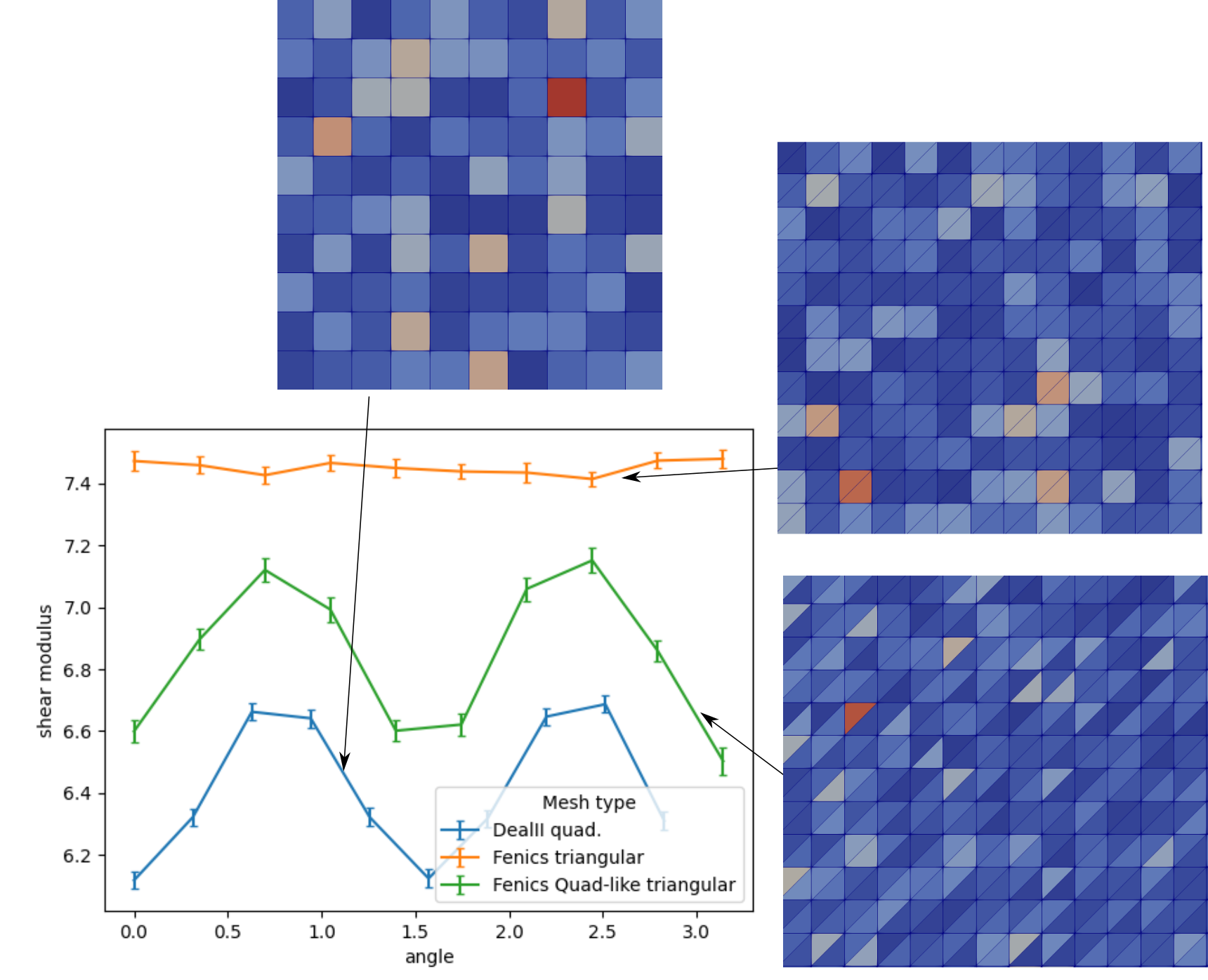
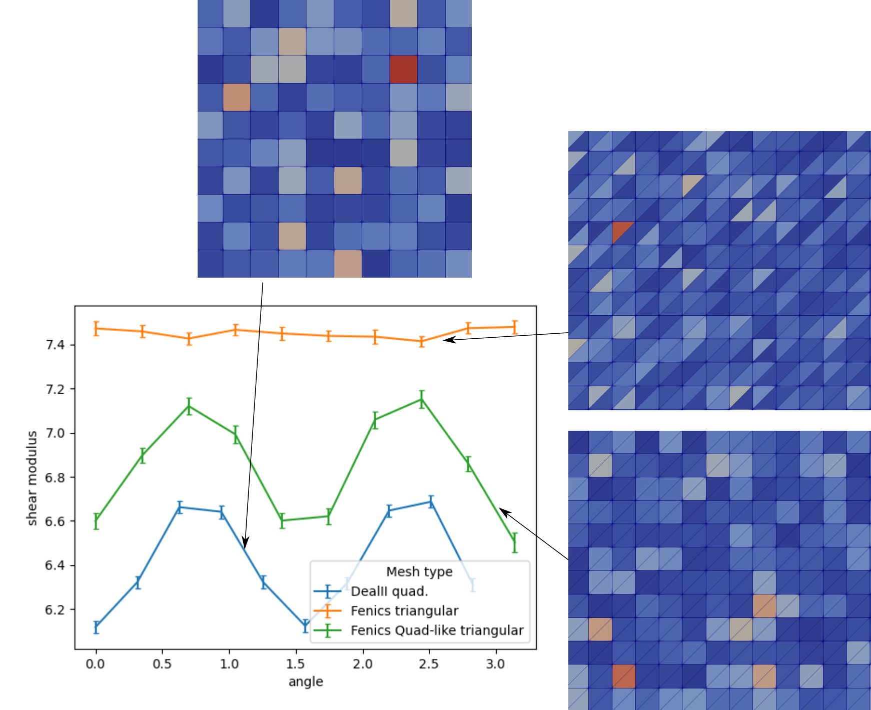
are geometrically anisotropic. Just plot the distribution of
angles the faces of your inhomogenities make with the x-axis. For
the quad-case, you'll get two discrete peaks at 0 and 90 degree.
for the triangular case, you get 0, 45 and 90 degree. So, from
this, the results do not seem surprising to me (just consider the
extreme case of cracks - if you have them only at 0 and 90 degree
oriented, this is unlikely to be isotropic). The fact that you
have randomly assigned elastic properties won't help to fix that.
A few examples (in 2d):
(1) equidistant circular inclusions in a matrix (matrix and inclusions two different isotropic linearly elastic materials) -> this should be isotropic if mesh size h->0
(2) equidistant square inclusions in a matrix, all aligned with x-axis (matrix and inclusions two different isotropic linearly elastic materials) -> probably anisotropic if mesh size h->0
(3) equidistant square inclusions in a matrix, random orientation
of inclusions (matrix and inclusions two different isotropic
linearly elastic materials) -> should be isotropic if mesh size
h->0 and number of orientations->infinity
(4) equidistant square inclusions in a matrix, random orientation of inclusions (random isotropic linearly elastic materials) -> should be isotropic if mesh size h->0 and number of orientations->infinity
Also to consider: In 3d, there are 21 elastic constants for a
linearly elastic material. In a mathematical 2d scenario, it
should be 6. This suggests that, in example (3), it is not
strictly necessary to have random orientation. Rather, a few
(equally spaced) discrete orientations might be good enough. If
that's the case, how many does one need? I'm betting on 6, not
sure though. Alternatively, one could replace the square
inclusions in (2) by regular polygons and ask how many vertices
the polygon needs for isotropy. Again, I'm betting on 6.
Related: Are there crystal structures with such a high degree of symmetry, that they are elastically isotropic? For dielectric properties, a cubic crystal is good enough already. But the dielectric tensor is rank 2 and the elastic one rank 4. So you'll need much more symmetry in the crystal; and considering that a crystal can have 6-fold rotational symmetry at most that might be impossible.
What I'm just noticing: Hexagonal crystals are elastically
isotropic perpendicular to the hexagonal axis. So, my bet on 6
might be good. And it might explain your observation that the
triangular elements are relatively isotropic (though maybe not
perfectly).
I hope that gives you some input. If you have definitive answers to any of the questions, I'm curious.
Regards,
Sebastian
--
The deal.II project is located at http://www.dealii.org/
For mailing list/forum options, see https://groups.google.com/d/forum/dealii?hl=en
---
You received this message because you are subscribed to the Google Groups "deal.II User Group" group.
To unsubscribe from this group and stop receiving emails from it, send an email to dealii+un...@googlegroups.com.
To view this discussion on the web visit https://groups.google.com/d/msgid/dealii/759917d0-227a-456e-bfac-00eab3ed71cdo%40googlegroups.com.
David F
To unsubscribe from this group and stop receiving emails from it, send an email to dea...@googlegroups.com.