discontinous contour over elements
75 views
Skip to first unread message

David Eaton
Jan 12, 2020, 10:42:25 PM1/12/20
to deal.II User Group
Dear dealii community,
I am new to dealii and this discussion forum. Recently, I am writting my own codes into dealii. I used Petrov-Galerkin method to solve incompressible Navier-Stokes equation. However, I encountered some weird results.
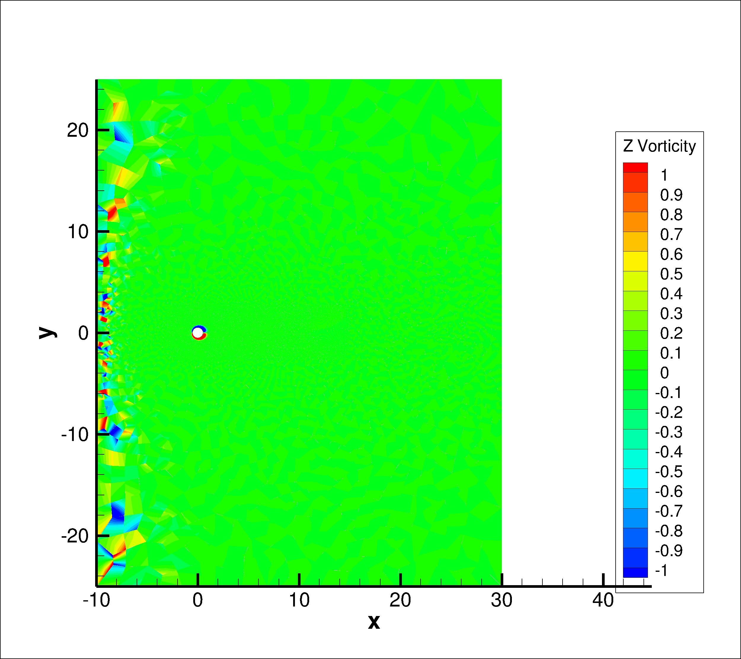
(1) This stabilized formulation is tested and running in code without any issue. However, it seems that the velocity fileld near the inlet, the left of figure "entire_domain", has large disturbances.
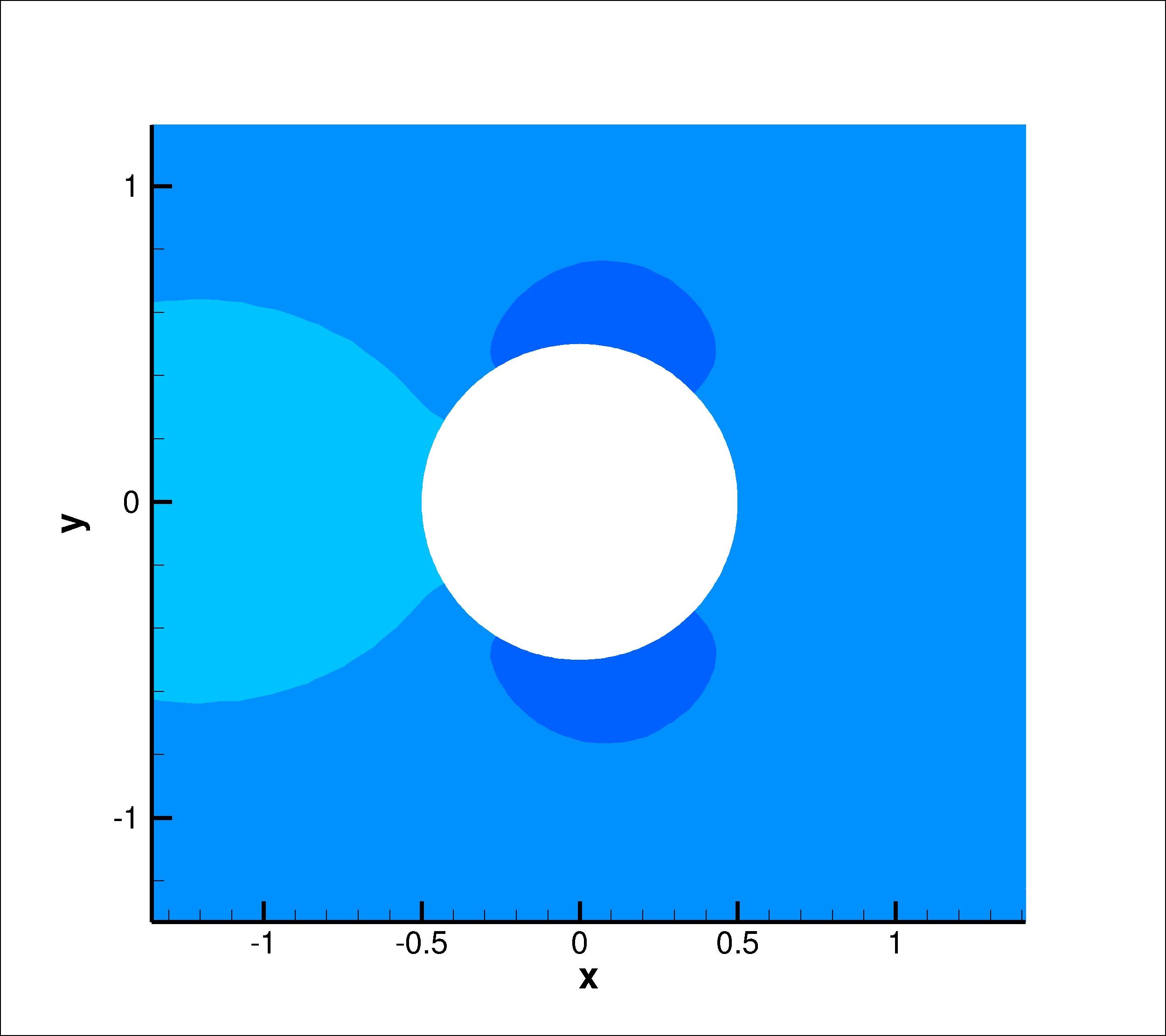
(2) In figure "zoom_in_1", there is no irregularity of the streamline. Furthermore, the calculated lift and drag matches with the literature. It seems that the irregularity of flow field near the inlet is caused by very large elements. However, this issue is not observed in another code.
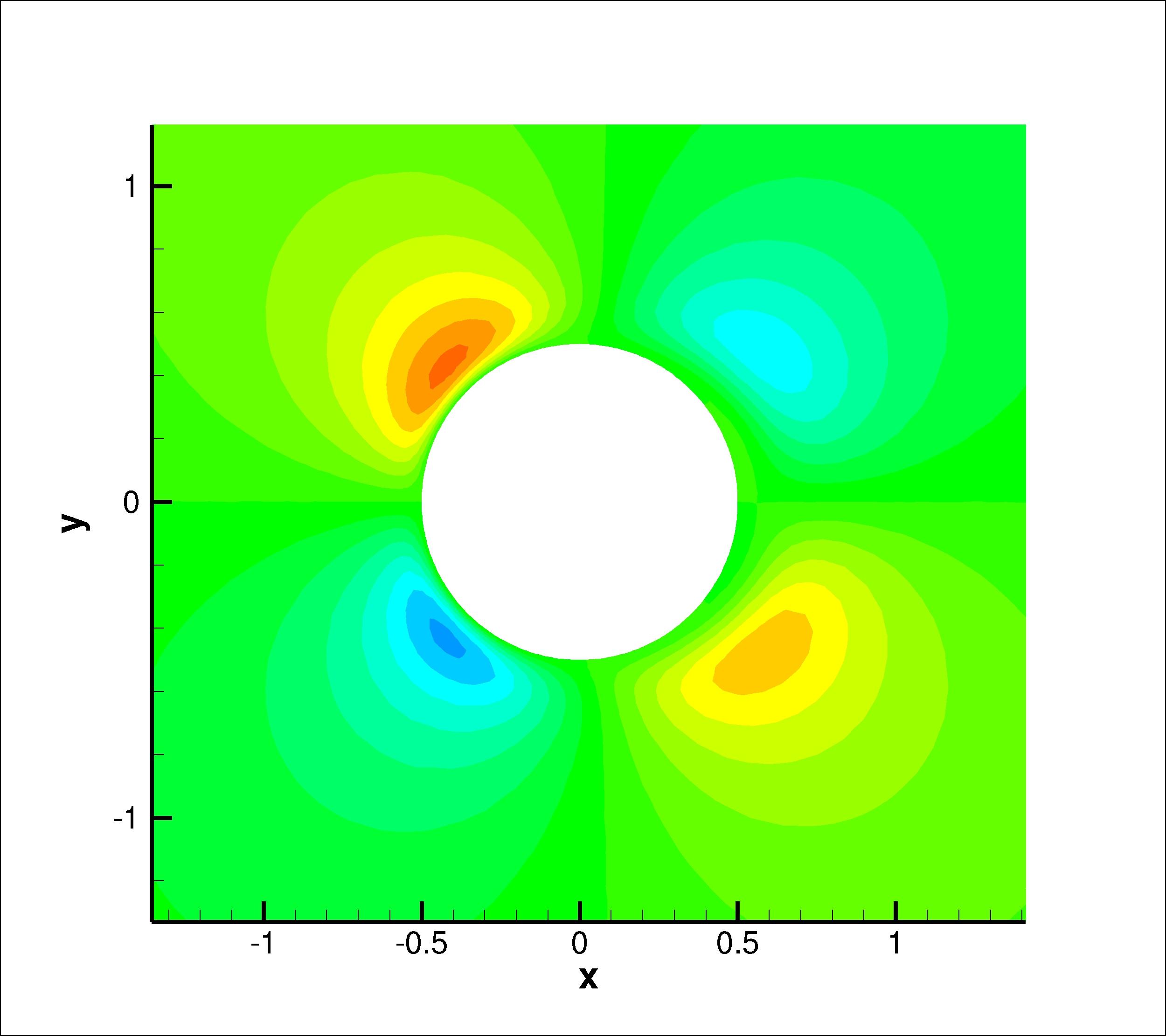
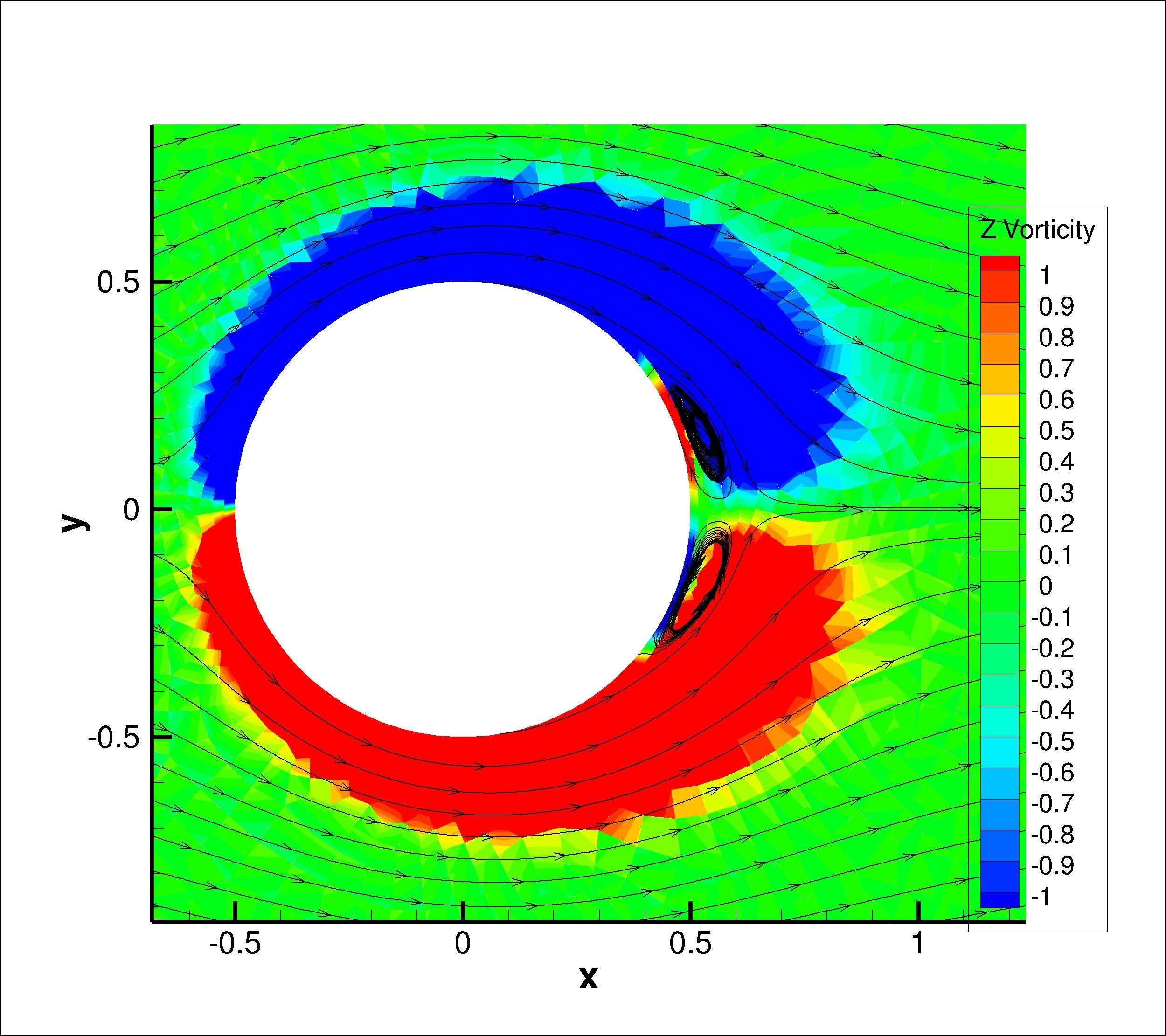
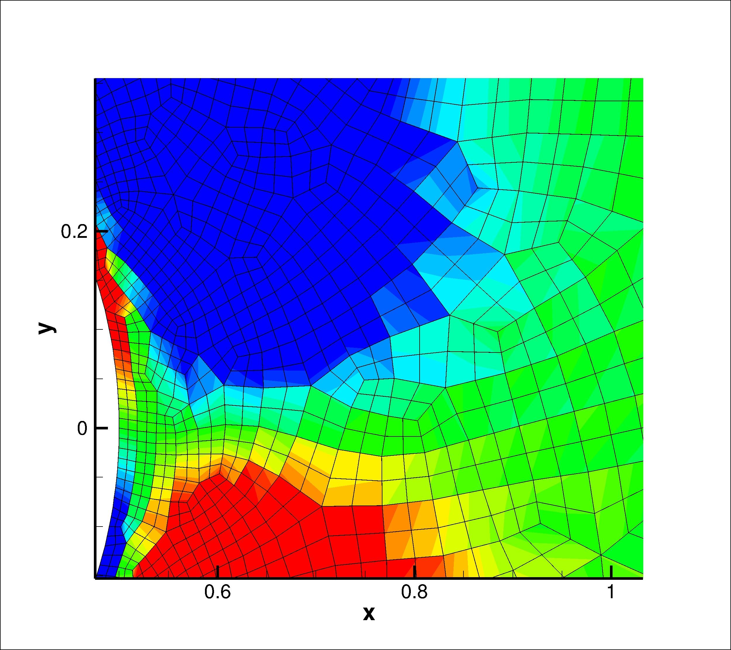
(3) The most weird issue to me is in figure "zoom_in_2". The contour of velocity, vorticity seems to be discontinuous to their neighboring elements. I believe I am using continuous Galerkin element and standard Gauss quadrature rule (4 Gauss integration points for 2D simulation). This issue does not appear in other codes using the same formation. Could anyone suggest a reason for this?
Best

Praveen C
Jan 12, 2020, 11:04:22 PM1/12/20
to Deal. II Googlegroup
Is your inflow conditions uniform ? If not then large elements at inflow could introduce errors.
If you compute vorticity as curl of velocity pointwise, then the vorticity would be discontinuous at element boundaries, since you are using only C0 elements for the velocity.
If you are averaging the computed vorticity or obtaining vorticity by an L2 projection, then they would be continuous. Maybe your other codes are doing something like this ?
Best
praveen
David Eaton
Jan 12, 2020, 11:18:04 PM1/12/20
to Praveen C, Deal. II Googlegroup
My inflow condition is uniform. This formulation and mesh is tested in a simple C++ code without library. The large mesh near the inflow does not give this problem.
Yes. I am using C0 element. I did calculation using tecplot. However, the results from a my C++ code does not give this issue either. Just now, I check the formulation again. Although I use Q2Q1 Taylor-Hood element without any stabilization, these issues are
still happening.
From: dea...@googlegroups.com <dea...@googlegroups.com> on behalf of Praveen C <cpra...@gmail.com>
Sent: Monday, January 13, 2020 12:04 PM
To: Deal. II Googlegroup <dea...@googlegroups.com>
Subject: Re: [deal.II] discontinous contour over elements
Sent: Monday, January 13, 2020 12:04 PM
To: Deal. II Googlegroup <dea...@googlegroups.com>
Subject: Re: [deal.II] discontinous contour over elements
--
The deal.II project is located at http://www.dealii.org/
For mailing list/forum options, see https://groups.google.com/d/forum/dealii?hl=en
---
You received this message because you are subscribed to the Google Groups "deal.II User Group" group.
To unsubscribe from this group and stop receiving emails from it, send an email to dealii+un...@googlegroups.com.
To view this discussion on the web visit https://groups.google.com/d/msgid/dealii/E1E13F63-7365-4328-9673-4073CDEED6CC%40gmail.com.

Wolfgang Bangerth
Jan 13, 2020, 5:24:22 PM1/13/20
to dea...@googlegroups.com
On 1/12/20 9:17 PM, David Eaton wrote:
> My inflow condition is uniform. This formulation and mesh is tested in a
> simple C++ code without library. The large mesh near the inflow does not give
> this problem.
> Yes. I am using C0 element. I did calculation using tecplot. However, the
> results from a my C++ code does not give this issue either. Just now, I check
> the formulation again. Although I use Q2Q1 Taylor-Hood element without any
> stabilization, these issues are still happening.
David -- we don't really know what formulation you are using, how you are
> My inflow condition is uniform. This formulation and mesh is tested in a
> simple C++ code without library. The large mesh near the inflow does not give
> this problem.
> Yes. I am using C0 element. I did calculation using tecplot. However, the
> results from a my C++ code does not give this issue either. Just now, I check
> the formulation again. Although I use Q2Q1 Taylor-Hood element without any
> stabilization, these issues are still happening.
implementing it, what you are comparing against, and a number of other factors.
If you have a formulation that computes u,p, and you are plotting the
vorticity, you need to expect that the isocontours are discontinuous for the
reasons Praveen already stated. If you are getting results that make no sense
to you, then the first step would be to ensure that your program is converging
as expected. To do this, choose a solution that you know and compute the error
norm; then ensure that the program yields error norms that decrease as
expected with mesh refinement.
Best
W.
--
------------------------------------------------------------------------
Wolfgang Bangerth email: bang...@colostate.edu
www: http://www.math.colostate.edu/~bangerth/
David Eaton
Jan 13, 2020, 8:29:53 PM1/13/20
to Wolfgang Bangerth, dea...@googlegroups.com
Thanks Wolfgang and Praveen for providing suggestions. I have tried to debugging this code for a while. I have attached this simple code on this email. I followed the instructions in tutorial closely. Hopefully, anyone could give some suggestions.
Best
D.
From: dea...@googlegroups.com <dea...@googlegroups.com> on behalf of Wolfgang Bangerth <bang...@colostate.edu>
Sent: Tuesday, January 14, 2020 6:24 AM
To: dea...@googlegroups.com <dea...@googlegroups.com>
Sent: Tuesday, January 14, 2020 6:24 AM
To: dea...@googlegroups.com <dea...@googlegroups.com>
Subject: Re: [deal.II] discontinous contour over elements
--
The deal.II project is located at http://www.dealii.org/
For mailing list/forum options, see https://groups.google.com/d/forum/dealii?hl=en
---
You received this message because you are subscribed to the Google Groups "deal.II User Group" group.
To unsubscribe from this group and stop receiving emails from it, send an email to dealii+un...@googlegroups.com.
To view this discussion on the web visit
https://groups.google.com/d/msgid/dealii/e1b55e95-a139-d62e-e786-61393cf84dc7%40colostate.edu.

Bruno Blais
Jan 14, 2020, 8:53:24 AM1/14/20
to deal.II User Group
Dear David,
How are you calculating the vorticity?
As Wolfgang and Praveen have mentioned, if you are using the DataPostProcessor, then this will use your shape functions to calculate the vorticity. However, your P2-P1 elements are only C0 continuous. Consequently, your vorticity can possibly be inherently discontinuous at the element edges. However, I am surprised that you obtain such strong discontinuity. In our code based on deal.ii (https://github.com/lethe-cfd/lethe) we implement stabilized formulations for the NS equations and the vorticity results for such cases are very smooth (even when represented using discontinuous shape functions.
Have you established the convergence of your code using manufactured solution? This is the first thing I would suggest. You can look at the applications_tests of lethe for some examples of easy manufactured solutions for the Incompressible Navier-Stokes equations. There are also common books that treat this issue (for instance : https://www.amazon.ca/Verification-Validation-Scientific-Computing-Oberkampf/dp/0521113601)
Please feel free to reach out if you have more questions.
Best
Bruno
To unsubscribe from this group and stop receiving emails from it, send an email to dea...@googlegroups.com.
David Eaton
Jan 15, 2020, 12:04:55 AM1/15/20
to Bruno Blais, deal.II User Group
Dear Bruno,
Thank you for your suggestions. I am going to take a look at Lethe and compare with my implementation. In stabilized formulation, I used quadrilateral element, instead of P2 P1 Taylor-Hood element. The used element is only C0 element. I also did not expect
such a discontinuity between elements. Although I use P2 P1 Taylor-Hood element without stabilization terms, the discontinuity is still there. Probably I made mistakes somewhere in setup. I also suspect that my solution is not converged. After taking a small
relative tolerance 1e-8, the discontinuity still appears. As Professor Wolfgang suggested, I am currently checking the convergence rate of this formulation. Thank you for your suggestions. If I cannot resolve this issue, I will update in the forum again.
Best
D.
From: dea...@googlegroups.com <dea...@googlegroups.com> on behalf of Bruno Blais <blais...@gmail.com>
Sent: Tuesday, January 14, 2020 9:53 PM
To: deal.II User Group <dea...@googlegroups.com>
Sent: Tuesday, January 14, 2020 9:53 PM
To: deal.II User Group <dea...@googlegroups.com>
To unsubscribe from this group and stop receiving emails from it, send an email to
dealii+un...@googlegroups.com.
To view this discussion on the web visit https://groups.google.com/d/msgid/dealii/5843231a-5b39-4f47-8b8e-ca3061959295%40googlegroups.com.
To view this discussion on the web visit https://groups.google.com/d/msgid/dealii/5843231a-5b39-4f47-8b8e-ca3061959295%40googlegroups.com.
Wolfgang Bangerth
Jan 15, 2020, 11:05:34 AM1/15/20
to dea...@googlegroups.com
On 1/14/20 10:04 PM, David Eaton wrote:
>
> Thank you for your suggestions. I am going to take a look at Lethe and compare
> with my implementation. In stabilized formulation, I used quadrilateral
> element, instead of P2 P1 Taylor-Hood element. The used element is only C0
> element. I also did not expect such a discontinuity between elements. Although
> I use P2 P1 Taylor-Hood element without stabilization terms, the discontinuity
> is still there. Probably I made mistakes somewhere in setup. I also suspect
> that my solution is not converged. After taking a small relative tolerance
> 1e-8, the discontinuity still appears.
David, you did not understand what we were saying: If you use C0 elements
>
> Thank you for your suggestions. I am going to take a look at Lethe and compare
> with my implementation. In stabilized formulation, I used quadrilateral
> element, instead of P2 P1 Taylor-Hood element. The used element is only C0
> element. I also did not expect such a discontinuity between elements. Although
> I use P2 P1 Taylor-Hood element without stabilization terms, the discontinuity
> is still there. Probably I made mistakes somewhere in setup. I also suspect
> that my solution is not converged. After taking a small relative tolerance
> 1e-8, the discontinuity still appears.
(think, piecewise linear) and you take derivatives to compute the vorticity,
then you automatically get a discontinuous function. That has nothing to do
with stabilization, solver tolerances, etc. It's just a consequence of the
fact that C0 elements and their shape functions have kinks and consequently
their derivatives are discontinuous.
David Eaton
Jan 15, 2020, 11:22:52 AM1/15/20
to dea...@googlegroups.com
I understand the C0 element is piecewise linear across elements. However, I did not experience the same issue in my own C++ code while I use C0 element with the Petrov Galerkin stabilization terms. Actually, I am very confused at this point. How could I get
rid of it while using C0 element?
Thanks
D.
From: dea...@googlegroups.com <dea...@googlegroups.com> on behalf of Wolfgang Bangerth <bang...@colostate.edu>
Sent: Thursday, January 16, 2020, 12:05 AM
To: dea...@googlegroups.com
To: dea...@googlegroups.com
Subject: Re: [deal.II] discontinous contour over elements
--
The deal.II project is located at http://www.dealii.org/
For mailing list/forum options, see https://groups.google.com/d/forum/dealii?hl=en
---
You received this message because you are subscribed to the Google Groups "deal.II User Group" group.
To unsubscribe from this group and stop receiving emails from it, send an email to dealii+un...@googlegroups.com.
The deal.II project is located at http://www.dealii.org/
For mailing list/forum options, see https://groups.google.com/d/forum/dealii?hl=en
---
You received this message because you are subscribed to the Google Groups "deal.II User Group" group.
To unsubscribe from this group and stop receiving emails from it, send an email to dealii+un...@googlegroups.com.
To view this discussion on the web visit
https://groups.google.com/d/msgid/dealii/f03c64fc-3736-340a-1cdc-f24749fb413f%40colostate.edu.
Wolfgang Bangerth
Jan 15, 2020, 12:03:03 PM1/15/20
to dea...@googlegroups.com
On 1/15/20 9:22 AM, David Eaton wrote:
> I understand the C0 element is piecewise linear across elements. However, I
> did not experience the same issue in my own C++ code while I use C0 element
> with the Petrov Galerkin stabilization terms. Actually, I am very confused at
> this point. How could I get rid of it while using C0 element?
Not easily. But you can project the discontinuous function (namely, the
> I understand the C0 element is piecewise linear across elements. However, I
> did not experience the same issue in my own C++ code while I use C0 element
> with the Petrov Galerkin stabilization terms. Actually, I am very confused at
> this point. How could I get rid of it while using C0 element?
gradient or vorticity of your velocity) onto a continuous finite element
field. Then you again have a continuous function -- albeit a different one, of
course, from the one you actually wanted.
Bruno Blais
Jan 15, 2020, 12:07:16 PM1/15/20
to deal.II User Group
An easy way to carry the projection that Wolfgang suggested is to use an L2 projection.
The L2 projection matrix is only a mass matrix and your right hand side is constructed by the integral of multiplication of the variable you want to project with the test function. Generally, this matrix is very very easy to invert. This will yield you the C0 representation of your discontinuous field (vorticity) such that the error between your C0 projection and your original field is minimized at the position of the gauss points.
This is a procedure we use to set the initial conditions in Lethe when the initial condition is a complex function (for instance a Taylor-Green vortex).
To unsubscribe from this group and stop receiving emails from it, send an email to dea...@googlegroups.com.
David Eaton
Jan 15, 2020, 12:57:33 PM1/15/20
to dea...@googlegroups.com
Professor Bangerth,
Thanks for the hints. I almost got what you mean. I will try to perform a L2 projection.
Regards
David
From: dea...@googlegroups.com <dea...@googlegroups.com> on behalf of Wolfgang Bangerth <bang...@colostate.edu>
Sent: Thursday, January 16, 2020, 1:03 AM
--
The deal.II project is located at http://www.dealii.org/
For mailing list/forum options, see https://groups.google.com/d/forum/dealii?hl=en
---
You received this message because you are subscribed to the Google Groups "deal.II User Group" group.
To unsubscribe from this group and stop receiving emails from it, send an email to dealii+un...@googlegroups.com.
The deal.II project is located at http://www.dealii.org/
For mailing list/forum options, see https://groups.google.com/d/forum/dealii?hl=en
---
You received this message because you are subscribed to the Google Groups "deal.II User Group" group.
To unsubscribe from this group and stop receiving emails from it, send an email to dealii+un...@googlegroups.com.
To view this discussion on the web visit
https://groups.google.com/d/msgid/dealii/4c39585b-55dd-c495-17b3-950b1e0f79d5%40colostate.edu.
David Eaton
Jan 15, 2020, 1:05:46 PM1/15/20
to dea...@googlegroups.com
Bruno,
Thanks for your explanation. Indeed, the gradient of velocity, vorticity, will be discontinuous over C0 elements. I will give a try and do a L2 projection. Surprisingly I did not experience it in my code before. I used standard Lagrangian shape functions and
continuous Galerkin method. I suppose dealii used the same interpolation functions. I have to investigate why my simple code does not have this discontinuous vorticity field.
Thanks
D.
From: dea...@googlegroups.com <dea...@googlegroups.com> on behalf of Bruno Blais <blais...@gmail.com>
Sent: Thursday, January 16, 2020, 1:07 AM
To: deal.II User Group
Sent: Thursday, January 16, 2020, 1:07 AM
To: deal.II User Group
To unsubscribe from this group and stop receiving emails from it, send an email to
dealii+un...@googlegroups.com.
To view this discussion on the web visit https://groups.google.com/d/msgid/dealii/bbe79d0e-d423-4df8-8f83-e4e934fedd7c%40googlegroups.com.
To view this discussion on the web visit https://groups.google.com/d/msgid/dealii/bbe79d0e-d423-4df8-8f83-e4e934fedd7c%40googlegroups.com.
David Eaton
Jan 17, 2020, 11:11:55 PM1/17/20
to Wolfgang Bangerth, dea...@googlegroups.com
Dear Professor Wolfgang Bangerth,
Thanks the help from you and the others. The issue of discontinuous vorticity field is resolved. Theoretically, I understand the gradient should be discontinuous for C0 elements. However, I still want to convince myself with a explanation. while I used Q2Q1
Taylor-Hood element, the discontinuous contour still appear. What could be the reason for this? On the other hand, I have a very simple FEM code using C0 elements without doing the projections. I just simply assembly the matrix, use a Lagrangian shape function
in C0 element and solve it with a linear solver. It does give a continuous contour without doing a projection. What could be the theoretical reason why it does not give a discontinuous contour? Is L2 projection is necessary step while computing gradients over
elements for C0 elements?
Thank you
Best regards
David
From: dea...@googlegroups.com <dea...@googlegroups.com> on behalf of Wolfgang Bangerth <bang...@colostate.edu>
Sent: Thursday, January 16, 2020 12:05 AM
To: dea...@googlegroups.com <dea...@googlegroups.com>
Subject: Re: [deal.II] discontinous contour over elements
--
The deal.II project is located at http://www.dealii.org/
For mailing list/forum options, see https://groups.google.com/d/forum/dealii?hl=en
---
You received this message because you are subscribed to the Google Groups "deal.II User Group" group.
To unsubscribe from this group and stop receiving emails from it, send an email to dealii+un...@googlegroups.com.
The deal.II project is located at http://www.dealii.org/
For mailing list/forum options, see https://groups.google.com/d/forum/dealii?hl=en
---
You received this message because you are subscribed to the Google Groups "deal.II User Group" group.
To unsubscribe from this group and stop receiving emails from it, send an email to dealii+un...@googlegroups.com.
To view this discussion on the web visit
https://groups.google.com/d/msgid/dealii/f03c64fc-3736-340a-1cdc-f24749fb413f%40colostate.edu.
Wolfgang Bangerth
Jan 18, 2020, 10:58:59 AM1/18/20
to David Eaton, dea...@googlegroups.com
On 1/17/20 9:11 PM, David Eaton wrote:
>
> Thanks the help from you and the others. The issue of discontinuous vorticity
> field is resolved. Theoretically, I understand the gradient should be
> discontinuous for C0 elements. However, I still want to convince myself with
> a explanation. while I used Q2Q1 Taylor-Hood element, the discontinuous
> contour still appear. What could be the reason for this?
And they should! You might be thinking that for Q2 functions, if you take the
>
> Thanks the help from you and the others. The issue of discontinuous vorticity
> field is resolved. Theoretically, I understand the gradient should be
> discontinuous for C0 elements. However, I still want to convince myself with
> a explanation. while I used Q2Q1 Taylor-Hood element, the discontinuous
> contour still appear. What could be the reason for this?
gradient, you should still get a linear function that is continuous. But the
Q2 functions are only quadratic on each cell separately; they still have a
kink at cell interfaces, and consequently their gradient is discontinuous.
> On the other hand, I
> have a very simple FEM code using C0 elements without doing the projections.
> I just simply assembly the matrix, use a Lagrangian shape function in C0
> element and solve it with a linear solver. It does give a continuous contour
> without doing a projection. What could be the theoretical reason why it does
> not give a discontinuous contour? Is L2 projection is necessary step while
> computing gradients over elements for C0 elements?
matrix" and "solve it", that sounds a lot like a projection to me.
David Eaton
Jan 18, 2020, 11:25:44 AM1/18/20
to Wolfgang Bangerth, dea...@googlegroups.com
Thank you for your explanations. Basically I formed a weak form of the PDE for one element and numerically integrate it at the Gaussian points based on the interpolation from the local nodes. Subsequently, I assemble the weak forms from all elements into a
global system matrix based on a local-to-global mapping of the nodes. After applying the boundary conditions, I solve this linear system using a linear solver in Intel mkl.
In deal.II, I took almost the same procedures. I formed the weak form for each element and assemble them based on the local-to-global mapping. After applying the boundary conditions, I solved it with the SparseDirectFUMPK solver. The only difference is that
I got a very clear discontinuous gradient over the edges of elements. I think the solution from deal.II is more close to the theorem of FEM, which explains the fundamental idea of weak form. However, I am puzzled at why I did not read it in the FEM books before.
Best
David
From: Wolfgang Bangerth <bang...@colostate.edu>
Sent: Saturday, January 18, 2020, 11:58 PM
To: David Eaton; dea...@googlegroups.com
Sent: Saturday, January 18, 2020, 11:58 PM
To: David Eaton; dea...@googlegroups.com
Subject: Re: [deal.II] discontinous contour over elements
Q
Wolfgang Bangerth
Jan 18, 2020, 11:49:20 AM1/18/20
to David Eaton, dea...@googlegroups.com
On 1/18/20 9:25 AM, David Eaton wrote:
> Thank you for your explanations. Basically I formed a weak form of the PDE for
> one element and numerically integrate it at the Gaussian points based on the
> interpolation from the local nodes. Subsequently, I assemble the weak forms
> from all elements into a global system matrix based on a local-to-global
> mapping of the nodes. After applying the boundary conditions, I solve this
> linear system using a linear solver in Intel mkl.
Right -- that gives you the solution (u,p) of the problem. But then what do
> Thank you for your explanations. Basically I formed a weak form of the PDE for
> one element and numerically integrate it at the Gaussian points based on the
> interpolation from the local nodes. Subsequently, I assemble the weak forms
> from all elements into a global system matrix based on a local-to-global
> mapping of the nodes. After applying the boundary conditions, I solve this
> linear system using a linear solver in Intel mkl.
you do to visualize whatever it is that you find is/isn't discontinuous?
David Eaton
Jan 18, 2020, 7:03:01 PM1/18/20
to Wolfgang Bangerth, dea...@googlegroups.com
I just use tecplot directly visualize the results. The vorticity contour from my simple code is continuous, and the results from deal.II is discontinuous (without L2 projection). Is it possible that the direct solver in Intel mkl did a similar projection step
internally?
Bruno Blais
Jan 20, 2020, 1:16:22 PM1/20/20
to deal.II User Group
Do you use Tecplot to calculate vorticity from the velocity field or do you calculate the vorticity from your code, and then visualize it from tecplot?
The way deal.II visualizes gradients (or vorticity in this case) is the correct way it should be done, because it is visualized on an "element basis", ensuring that the real discontinuities in the fields are seen. Many other software will smoothen the discontinuous field by using some sort of averaging and then output these values at the nodes. This gives the illusion that the fields are continuous, when they are not in reality (the averaging introduces the continuity).
Consequently, this really depends on the procedure you are using to visualize your other results.
Wolfgang Bangerth
Jan 21, 2020, 10:48:23 AM1/21/20
to dea...@googlegroups.com
On 1/18/20 5:02 PM, David Eaton wrote:
> I just use tecplot directly visualize the results. The vorticity contour from
> my simple code is continuous, and the results from deal.II is discontinuous
> (without L2 projection).
Ah, I think that is it. Bruno was already on the right track.
> I just use tecplot directly visualize the results. The vorticity contour from
> my simple code is continuous, and the results from deal.II is discontinuous
> (without L2 projection).
I bet that your own code outputs the solution in a way that assigns only one
value to each node, and tecplot then computes a discontinuous gradient that it
averages at each node again from the adjacent cells. On the other hand,
deal.II outputs the value at each node as many times as there are adjacent
cells, and tecplot doesn't know how to average in that case.
In other words, what tecplot is doing *internally* is to do a projection (or
some other averaging operation) so that it *shows* you a continuous gradient
or vorticity field. But this is just another case where what you *see* is not
actually what it *is*. The gradient is discontinuous, regardless of what
tecplot shows you.
David Eaton
Jan 22, 2020, 4:59:38 AM1/22/20
to Wolfgang Bangerth, dea...@googlegroups.com
Professor Wolfgang Bangerth and Bruno Blais,
Thank you for your explanations. I get clear about this problem now.
Best
D.
From: dea...@googlegroups.com <dea...@googlegroups.com> on behalf of Wolfgang Bangerth <bang...@colostate.edu>
Subject: Re: [deal.II] discontinous contour over elements
--
The deal.II project is located at http://www.dealii.org/
For mailing list/forum options, see https://groups.google.com/d/forum/dealii?hl=en
---
You received this message because you are subscribed to the Google Groups "deal.II User Group" group.
To unsubscribe from this group and stop receiving emails from it, send an email to dealii+un...@googlegroups.com.
The deal.II project is located at http://www.dealii.org/
For mailing list/forum options, see https://groups.google.com/d/forum/dealii?hl=en
---
You received this message because you are subscribed to the Google Groups "deal.II User Group" group.
To unsubscribe from this group and stop receiving emails from it, send an email to dealii+un...@googlegroups.com.
To view this discussion on the web visit
https://groups.google.com/d/msgid/dealii/cc811240-1952-ef7f-c5b9-4de5bdfe3ac9%40colostate.edu.
Reply all
Reply to author
Forward
0 new messages