Div-conforming elements in 3D
137 views
Skip to first unread message

Konrad Simon
Dec 7, 2020, 12:48:01 PM12/7/20
to deal.II User Group
Dear Deal.ii community,
Sorry for spamming the mailing list again. I posted some of the below stuff already in another post but that might have been with too many unnecessary details and confusing ideas from my side.
I am not sure if I stumbled over something and would like to report on that.
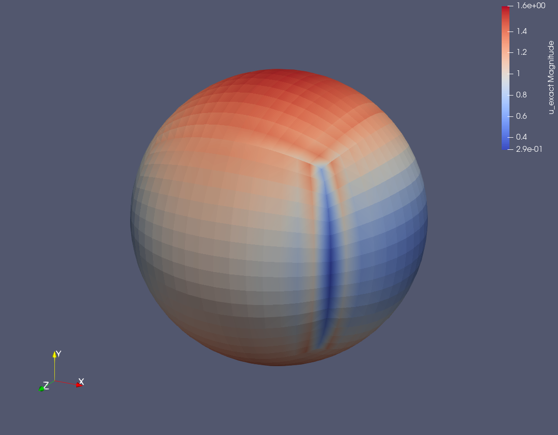
Goal is to project a given function onto a finite element space over a certain mesh. The focus here shall be on H(div)-conforming elements such as Raviart-Thomas and Brezzi-Douglas-Marini Elements.
I do so with several different meshes and I noticed an inconsistency in the projection on meshes with, say, not so simple topology (e.g., holes and voids).
Observations:
1. The problematic meshes do have faces with non-standard orientation. My first thought was this was not carried over to the mapping of the H(div)-basis but I was wrong. The mesh orientation is consistent (as far as I can tell). A cube, for example, is not problematic. Please see two example plots below.
2. The issue arises with both Raviart-Thomas and Brezzi-Douglas-Marini Elements.
3. The issue arises in 3D only.
Any ideas what I ran into?
Best,
Konrad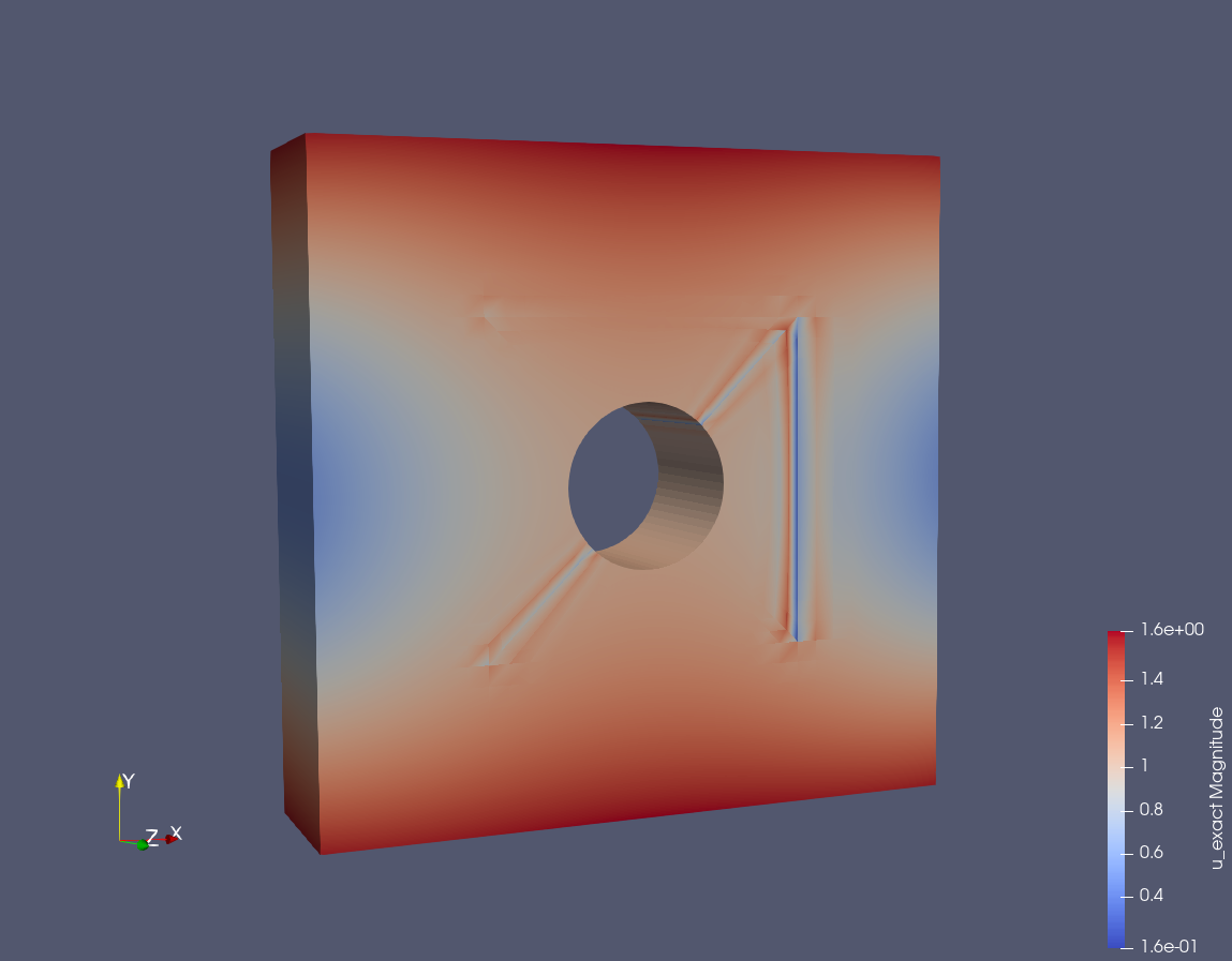
Konrad

Wells, David
Dec 8, 2020, 4:56:44 PM12/8/20
to deal.II User Group
Hi Konrad,
This isn't a very satisfying answer but, to the best of my knowledge, these Hdiv elements weren't written with general unstructured 3D meshes in mind. I suspect, without looking more closely, that this is a problem on our side.
We document this for the FE_RaviartThomasNodal class but for FE_RaviartThomas this is just a comment in the source file. Would you be willing to write a patch explaining things better for the other Hdiv classes?
Best,
David
From: dea...@googlegroups.com <dea...@googlegroups.com> on behalf of Konrad Simon <ksimo...@gmail.com>
Sent: Monday, December 7, 2020 12:48 PM
To: deal.II User Group <dea...@googlegroups.com>
Subject: [deal.II] Div-conforming elements in 3D
Sent: Monday, December 7, 2020 12:48 PM
To: deal.II User Group <dea...@googlegroups.com>
Subject: [deal.II] Div-conforming elements in 3D
--
The deal.II project is located at http://www.dealii.org/
For mailing list/forum options, see https://groups.google.com/d/forum/dealii?hl=en
---
You received this message because you are subscribed to the Google Groups "deal.II User Group" group.
To unsubscribe from this group and stop receiving emails from it, send an email to dealii+un...@googlegroups.com.
To view this discussion on the web visit https://groups.google.com/d/msgid/dealii/fa304b41-f83f-4c96-a2f7-c4e9e813553fn%40googlegroups.com.
Konrad Simon
Dec 9, 2020, 9:44:58 AM12/9/20
to deal.II User Group
Hi David,
Many thanks for the hint. After some research I believe I stumbled over this issue#7970? Let's see what I can do.
Many thanks for the hint. After some research I believe I stumbled over this issue#7970? Let's see what I can do.
Best,
Konrad
Konrad
Konrad Simon
Dec 10, 2020, 12:50:33 PM12/10/20
to deal.II User Group
Dear David, dear all,
2. The fix does not work for lowest order BDM elements.
It seems like the issue is much more involved than I initially thought. Some updates since I started going into this issue.
1. I could solve the problem for lowest order RaviartThomas Elements (RT). This is already good.
2. The fix does not work for lowest order BDM elements.
3. The fix does not work for higher order elements, neither BDM nor RT elements
Suspected reason: For shape functions of higher order elements (whose normal components) are supported on a face flipping the sign on a flipped face is not enough since the flipped face changes/reverts the ordering of the face dofs hence the translation of local to global numbering of degrees of freedom changes for cells with flipped faces. I am not sure but at least I suspect that. Is this being taken care of by Deal.II somewhere?
I will go on chasing the bug and hopefully come up with a merge request soon.
Best,
Konrad
Konrad

Jean-Paul Pelteret
Dec 10, 2020, 5:39:08 PM12/10/20
to dea...@googlegroups.com, Konrad Simon
HI Konrad,
I have no familiarity with the H-div elements, so I could be wrong with this suggestion...
The Fe_Nedelec element suffered from a similar issue, where adjacent cells had to agree on the edge sense/directionality. This requirement could not be unconditionally guaranteed for that element type, hence the following note in its introduction
Even if this element is implemented for two and three space dimensions, the definition of the node values relies on consistently oriented faces in 3D. Therefore, care should be taken on complicated meshes.
The more recent FE_NedelecSZ element resolves the issue by querying the vertex numbers that make up each edge/face and applying a rule that gives each face and its bounding edges a direction. This means that the orientation of the face/edges is always consistent no matter which of the two cells that share the face you're on. The details are more explicitly laid out in the FE_NedelecSZ introduction, as well as the two papers that are listed therein.
Now, I'm by no means certain that underlying issue that you're seeing here is the same as that which plagued the canonical Nedelec element (although your comment #3 makes me suspect that it could be). But if it is, then perhaps what was done to fix the orientation conflict in the Zaglmayr formulation of the Nedelec element can serve as inspiration for a fix to the BDM and RT elements?
Thanks for looking into this, and I hope that you have some success at finding a solution to the problem. Naturally, if there's anything that we can do to help please let us know. It would be very nice to have a robust implementation to these elements in the library, so anything that you might be willing to contribute would be greatly appreciated!
Best,
Jean-Paul
To view this discussion on the web visit https://groups.google.com/d/msgid/dealii/883fee09-6fba-4d38-914d-869e2e7058adn%40googlegroups.com.
Konrad Simon
Dec 12, 2020, 2:07:19 PM12/12/20
to deal.II User Group
Hi Jean-Paul,
On Thursday, December 10, 2020 at 11:39:08 PM UTC+1 Jean-Paul Pelteret wrote:
HI Konrad,
I have no familiarity with the H-div elements, so I could be wrong with this suggestion...
The Fe_Nedelec element suffered from a similar issue, where adjacent cells had to agree on the edge sense/directionality. This requirement could not be unconditionally guaranteed for that element type, hence the following note in its introduction
Even if this element is implemented for two and three space dimensions, the definition of the node values relies on consistently oriented faces in 3D. Therefore, care should be taken on complicated meshes.
Yes, this issue is similar. I assume I will need to check that for these elements as well since I also need them.
The more recent FE_NedelecSZ element resolves the issue by querying the vertex numbers that make up each edge/face and applying a rule that gives each face and its bounding edges a direction. This means that the orientation of the face/edges is always consistent no matter which of the two cells that share the face you're on. The details are more explicitly laid out in the FE_NedelecSZ introduction, as well as the two papers that are listed therein.
This is a nice alternative for the Nedelec element. Often though such elements are used in conjunction with H1 or H(div) conformal elements and need to satisfy a compatibility condition (stronger than just LBB, i.e., they must form a bounded co-chain complex that is a subcomplex to something else). I am not sure that this element does satisfy this condition together with classical RT elements etc.
Now, I'm by no means certain that underlying issue that you're seeing here is the same as that which plagued the canonical Nedelec element (although your comment #3 makes me suspect that it could be). But if it is, then perhaps what was done to fix the orientation conflict in the Zaglmayr formulation of the Nedelec element can serve as inspiration for a fix to the BDM and RT elements?
Thanks for looking into this, and I hope that you have some success at finding a solution to the problem. Naturally, if there's anything that we can do to help please let us know. It would be very nice to have a robust implementation to these elements in the library, so anything that you might be willing to contribute would be greatly appreciated!
Lowest order RaviartThomas is already fixed. I will hunt down this issue as good as I can. I might need some help with local and global dof numbering conventions. I will also try to move the discussion to the issue page on github.
Best,
Konrad
Konrad
Konrad Simon
Dec 16, 2020, 3:33:57 PM12/16/20
to deal.II User Group
Dear Jean-Paul, dear Deal.II community,
I partially solved the problem of sign flipping and permuting the degrees of freedom and would like to come up with a merge-request at least for the RaviartThomas elements. I have some questions before I can go on and guidance would be appreciated.
I decided to go a similar way that is taken for FE_Q elements. There one has only a permutation of dofs on non-standard or flipped or rotated faces since a sign change in the orientation does not matter. A vector of size n_faces_per_cell of which each contains a table mapping each face_dof and each of the 8 combinations of the flags (non-standard | flipped | rotated) to an offset of that face_dof. The system behind that relies on the lexicographic ordering of dofs if I understand correctly. My questions:
1. Is there a similar numbering scheme for dofs on faces for RT elements. There one has face moments as dofs and it is not fully clear to me what lexicographic means there (if such a principle is usable there at all).
2. If the order (and sign) of face_dofs if permuted for each of the flags (non-standard | flipped | rotated) then in what order are the permutations applied? (They do not commute)
I would like to avoid hard-coding that (I think up to order 2 would be doable -> but already 54 face_dofs).
I believe the table similar to adjust_quad_dof_index_for_face_orientation_table of FE_Q_Base makes sense but I guess every FE inheriting from FE_PolyTensor must implement such a table then. This is a lot of work and more complicated for Nedelec elements.
Best,
Konrad
I believe the table similar to adjust_quad_dof_index_for_face_orientation_table of FE_Q_Base makes sense but I guess every FE inheriting from FE_PolyTensor must implement such a table then. This is a lot of work and more complicated for Nedelec elements.
Best,
Konrad
Konrad Simon
Dec 18, 2020, 2:50:55 PM12/18/20
to deal.II User Group
Dear Deal.II community,
Suppose I chose FE_Nedelec<3> of some order as finite element.
1. Is there a way to query for a given <code>cell_dof_index</code> whether it is a face_dof and to get the <code>face_index</code>?
2. If this dof is a <code>line_dof</code> is it by definition also a <code>face_dof</code>? I need to exclude line_dofs and treat them separately.
3. Is there a convention that (if I am not using FESystem) in the set of all <code>cell_dofs</code> all <code>line_dofs</code> come before all <code>face_dofs</code> and only then the <code>volume_dofs</code>?
I am asking since I am trying to come up with a patch for RaviartThomas and a pattern to implement it in the current structures without interfering with them (too much).
Best,
Konrad
Konrad
Jean-Paul Pelteret
Dec 29, 2020, 3:31:49 PM12/29/20
to dea...@googlegroups.com
Hi Konrad,
I'm sorry for taking some time to reply. To be honest, the inner working of the FE classes is not something that I've ever had the time or opportunity to dig into, so I'm really not well positioned to answer many of your questions. I'm glad that you've submitted a PR for the work that you've done thus far, and I hope that you can be guided by someone who has more familiarity with this part of the library.
What I can say, though, is that the various FE classes have been implemented by numerous people over time, and the logic that dictates the way that the DoFs are assigned varies between each FE. We have always considered this to be perfectly fine -- this is, to the average person, an implementational detail, and the interface that we have to interrogate DoFs (e.g. which vector component they're associated with, whether or not they have support points, etc...) seems to be sufficiently rich to most users. So, as the end user, you shouldn't be writing code that would care that the FE_Q element orders DoFs like this: [N_{0,x} N_{0,y} N_{0,z} N_{1,x} ...] ; while IIRC the FE_DGQ element orders DoFs like this: [N_{0,x} N_{1,x} N_{2,x} ... N_{0,y} N_{1,y} ...] .
So, returning to your original set of questions: In general, I don't believe that it can be assumed that all cell vertex DoFs are enumerated before line/edges DoFs, before face DoFs, before cell interior DoFs. Through the FiniteElementData class, the FiniteElement base class seems to have a set of n_dofs_per_[vertex,line,face,cell]_dofs() and get_first_[line/quad/hex]_index() functions, which does suggest that I'm wrong about this, so I'd be happy to be corrected on this point. (Question: What does a vertex/edge/face DoF even mean for a DG element?) Maybe these are the exact functions that you were looking for (and maybe with this , if the [vertex,edge,face,cell] groupings do apply, you can map from the cell DoF->associated geometric entity using these functions). But I don't that they would help understanding the ordering (e.g. lexiographic or something else; element base index fast or spacedim fast, etc.) within each grouping -- again, that's probably a decision that was left to the designer of each FE class, and I don't think that there's been a need for any consistency between the classes. But again, I'm just putting my thoughts out there and anticipate being corrected on these points.
I get the feeling that there is no overlap in assignment of DoFs between geometric entities. Consider each of these entities not to have closure: so you're actually referring to DoFs associated with the cell interior (excl. faces, edges and vertices), face interior (excl edges and vertices) and edge interiors (excl. vertices). To me, that the only sensible interpretation of this.
Thanks for giving this so much thought, and for the interesting questions. I've certainly got a lot to learn from the responses that may come from the other developers.
Best,
Jean-Paul
--
The deal.II project is located at http://www.dealii.org/
For mailing list/forum options, see https://groups.google.com/d/forum/dealii?hl=en
---
You received this message because you are subscribed to the Google Groups "deal.II User Group" group.
To unsubscribe from this group and stop receiving emails from it, send an email to dealii+un...@googlegroups.com.
To view this discussion on the web visit https://groups.google.com/d/msgid/dealii/c6ceaa83-318f-438b-9982-21e2d67a39e8n%40googlegroups.com.
Konrad Simon
Dec 29, 2020, 4:44:15 PM12/29/20
to deal.II User Group
Dear Jean-Paul,
Many thanks for your reply.
On Tuesday, December 29, 2020 at 9:31:49 PM UTC+1 Jean-Paul Pelteret wrote:
Hi Konrad,
I'm sorry for taking some time to reply. To be honest, the inner working of the FE classes is not something that I've ever had the time or opportunity to dig into, so I'm really not well positioned to answer many of your questions. I'm glad that you've submitted a PR for the work that you've done thus far, and I hope that you can be guided by someone who has more familiarity with this part of the library.
It will be my pleasure if other people will be able to benefit from implementations that I had to add and to contribute it as well as I benefited from other peoples‘ work. Let‘s hope that the stuff I asked to add makes sense.
What I can say, though, is that the various FE classes have been implemented by numerous people over time, and the logic that dictates the way that the DoFs are assigned varies between each FE. We have always considered this to be perfectly fine -- this is, to the average person, an implementational detail, and the interface that we have to interrogate DoFs (e.g. which vector component they're associated with, whether or not they have support points, etc...) seems to be sufficiently rich to most users. So, as the end user, you shouldn't be writing code that would care that the FE_Q element orders DoFs like this: [N_{0,x} N_{0,y} N_{0,z} N_{1,x} ...] ; while IIRC the FE_DGQ element orders DoFs like this: [N_{0,x} N_{1,x} N_{2,x} ... N_{0,y} N_{1,y} ...] .
So, returning to your original set of questions: In general, I don't believe that it can be assumed that all cell vertex DoFs are enumerated before line/edges DoFs, before face DoFs, before cell interior DoFs. Through the FiniteElementData class, the FiniteElement base class seems to have a set of n_dofs_per_[vertex,line,face,cell]_dofs() and get_first_[line/quad/hex]_index() functions, which does suggest that I'm wrong about this, so I'd be happy to be corrected on this point. (Question: What does a vertex/edge/face DoF even mean for a DG element?) Maybe these are the exact functions that you were looking for (and maybe with this , if the [vertex,edge,face,cell] groupings do apply, you can map from the cell DoF->associated geometric entity using these functions). But I don't that they would help understanding the ordering (e.g. lexiographic or something else; element base index fast or spacedim fast, etc.) within each grouping -- again, that's probably a decision that was left to the designer of each FE class, and I don't think that there's been a need for any consistency between the classes. But again, I'm just putting my thoughts out there and anticipate being corrected on these points.
In my humble opinion the FE should only be implemented in terms of a reference element. This is, as far as I can tell, the case for all elements in Deal.II. The mapping though is problematic on complicated domains and I saw that one needs to renumber or switch signs for some shape functions if one wants to satisfy continuity conditions for the respective spaces. This is partly taken care of by the DoFHandler (see renumbering of FE_Q on faces) class which confused me, while other parts like the sign change is not. I guess I got the idea. Also, the concept of (generalized) support points is nice but sometimes it is not really clear to me if this is helpful in the context of element pairings (for example in the language of finite element exterior calculus where this concept does not really make sense globally). I may be wrong and miss a point here and would love to get a lesson.
I get the feeling that there is no overlap in assignment of DoFs between geometric entities. Consider each of these entities not to have closure: so you're actually referring to DoFs associated with the cell interior (excl. faces, edges and vertices), face interior (excl edges and vertices) and edge interiors (excl. vertices). To me, that the only sensible interpretation of this.
This is partly what is not fully clear to me. Vertex/edge/face/volume dofs (again FEEC) depends on the functionals that define them and less on location (a Raviart-Thomas or Nedelec shape function is not regular enough for point evaluations, although viewing them as a polynomial suggests so).
Thanks for giving this so much thought, and for the interesting questions. I've certainly got a lot to learn from the responses that may come from the other developers.
As I said, I hope other people can benefit from that but I am not super familiar with this part of the library as well. Let‘s see what the code reviewers will say.
All the best wishes for the new year and stay healthy in these crazy times!
Konrad
Reply all
Reply to author
Forward
0 new messages