RUMBA 12-35V - maybe not, burned re-settable Fuse
1,946 views
Skip to first unread message

Bogdan Bednarczyk
Nov 10, 2013, 8:50:49 PM11/10/13
to connected-commu...@googlegroups.com
Hi guys,
I did get the Rumba from Reprapdiscount did i do something wrong?
--
Cheers
Bogdan

John Bosua
Nov 10, 2013, 9:35:34 PM11/10/13
to connected-commu...@googlegroups.com
Hey Bogdan,
You should have waited until you spoke to some of us!
You have to quite a bit of firmware current limiting to do before you just hook it up to 24 volts and press go.
Dont try any thing else until you speak to me at the space next.
Frankly I'm surprised it lasted 10 mins.
You seem to run at these things like a bull at a gate without any research and then get upset when it blows up.
I will talk you through it at the space next time I see you.
hopefully you just killed the heated bed mosfet which is way undersized anyway.
JB
--
You received this message because you are subscribed to the Google Groups "Connected Community HackerSpace" group.
To unsubscribe from this group and stop receiving emails from it, send an email to connected-community-h...@googlegroups.com.
To post to this group, send an email to connected-commu...@googlegroups.com.
To view this discussion on the web, visit https://groups.google.com/d/msgid/connected-community-hackerspace/CAOhh4dv71NfTn9%2BP7b0kkSs0eU3HaOjMGvUuaJoVnqbLJsueyA%40mail.gmail.com.
For more options, visit https://groups.google.com/groups/opt_out.

Stuart Young
Nov 11, 2013, 12:00:56 AM11/11/13
to CCHS
One thing of note:
This sort of thing happens when you connect a standard 12V heated bed to a board running a 24V supply.For reference, my Kapton based 24V heated bed produces about 200W and draws ~8.3A.
Also of note, the larger heated bed PTC fuse is only rated for 16V, so IMO it should not be sold as capable of running the heated bed at higher than 15V.
To view this discussion on the web, visit https://groups.google.com/d/msgid/connected-community-hackerspace/519C167C-E348-47C2-9EF0-AE575AEE1C19%40gmail.com.
--
Stuart Young (aka Cefiar)

Luke Weston
Nov 11, 2013, 1:42:32 AM11/11/13
to connected-commu...@googlegroups.com
If it really requires particular software configuration prior to plugging in power or else it blows up then that's pathetic engineering and user experience.
--
This email is intended only for the personal and confidential use of the human(s) named above. If intercepted by an extraterrestrial civilization, all opinions expressed in this email are my own and do not necessarily reflect the opinion of mankind as a whole.
Hardware should never ever be designed such that it is dependent on the software being put in a certain state, or never put in a certain state, or else it blows up. If the user specifically has to edit the code, set the HARDWARE_DONT_CATCH_FIRE variable, recompile and reflash the code to the board then they're doing something very, very wrong with hardware design.
Also, PPTCs are just crap at these power levels, I don't know why they've kept using them on the supposedly modern, advanced RUMBA/RAMBO designs.
To view this discussion on the web, visit https://groups.google.com/d/msgid/connected-community-hackerspace/CAPh9M%2BESc7sMzXGjk5Zox6H5WHpteb87kgHxbhxE%3DY%2BXLkS_UA%40mail.gmail.com.
For more options, visit https://groups.google.com/groups/opt_out.
--
This email is intended only for the personal and confidential use of the human(s) named above. If intercepted by an extraterrestrial civilization, all opinions expressed in this email are my own and do not necessarily reflect the opinion of mankind as a whole.
John Bosua
Nov 11, 2013, 1:55:44 AM11/11/13
to connected-commu...@googlegroups.com
Thats only if you are running a 12v extruder heater and 12v heated bed on 24v. the firmware has current limit functions which gives you the flexibility to do it. But not right out of the box. So it's not a crap design just not enough knowledge by the user.
I have been running it successfully for a year now with no problems (I did put in a bigger mosfet for the heated bed )
JB
To view this discussion on the web, visit https://groups.google.com/d/msgid/connected-community-hackerspace/CAEPooQG5%3DQTZH9L3yz1ZYcnAo_bQpeCcbjp0n7uMKtL25GsRuw%40mail.gmail.com.
Stuart Young
Nov 11, 2013, 1:58:29 AM11/11/13
to CCHS
Re: PTCs
RAMPS had them, which as a design is now a number of years old. Most of the newer electronics designs do not have them.
That said, RUMBA is a newer derivative, and they haven't yet learned the lesson Re: PTCs it seems.RAMPS had them, which as a design is now a number of years old. Most of the newer electronics designs do not have them.
To view this discussion on the web, visit https://groups.google.com/d/msgid/connected-community-hackerspace/CAEPooQG5%3DQTZH9L3yz1ZYcnAo_bQpeCcbjp0n7uMKtL25GsRuw%40mail.gmail.com.

Clifford Heath
Nov 11, 2013, 2:10:59 AM11/11/13
to connected-commu...@googlegroups.com
As an indication of what real pro-quality stuff can do, there are
Fluke multimeters which you can set on a 50 micro-amp range
and leave plugged into a 240V wall outlet, with no harm.
That's robust design :)
Clifford Heath.
> To view this discussion on the web, visit https://groups.google.com/d/msgid/connected-community-hackerspace/C116FA68-5AB5-4304-B585-DDAA0D837AE1%40gmail.com.
Fluke multimeters which you can set on a 50 micro-amp range
and leave plugged into a 240V wall outlet, with no harm.
That's robust design :)
Clifford Heath.
Bogdan Bednarczyk
Nov 11, 2013, 2:40:49 AM11/11/13
to connected-commu...@googlegroups.com
I might be jumping into hot water with both feet,
but if the board said 12 -35v and i only use 24v,....then I agree with Luke its a poor consumer experience. Its either able or not able.........RAMPS had 12 and only after studding the design you are able to draw conclusions..
It should have a !!!! there or a NOTE: * with references... or something
but if the board said 12 -35v and i only use 24v,....then I agree with Luke its a poor consumer experience. Its either able or not able.........RAMPS had 12 and only after studding the design you are able to draw conclusions..
It should have a !!!! there or a NOTE: * with references... or something
I don't want to ask for everything because that can be annoying
But as you know, I will accept any help with thanks,
Thanks guys
Bogdan
Bogdan
--
Cheers
Bogdan
Cheers
Bogdan
John Bosua
Nov 11, 2013, 3:20:22 AM11/11/13
to connected-commu...@googlegroups.com
You can blame the board as much as you like but if you had a 24v heatbed and a 24v extruder heater and ran the board at 24v nothing would have burned up.
You chose to put 24volts into a 12volt cartridge heater and 24 volts into a 12 volt heatbed . What the hell did you think would happen!
12volts into 1.6 ohms =7.5 Amps = 90 watts
24volts into 1.6 ohms= 15 Amps =360 watts
Thats why your 11 amp fuse exploded into flames. (It may have survived if you had a big ass fan on it)
Both Michael and myself removed the fuses because we calculated the current draw was too high. Thats why I said you should have checked with us first.
It most definately was your fault the board blew up.
So dont keep blaming the RUMBA board .
JB
To view this discussion on the web, visit https://groups.google.com/d/msgid/connected-community-hackerspace/CAOhh4dupZBDCDjr0Qc6fMKnKt1WieAU00JL9SqFZkdTZZZnXXg%40mail.gmail.com.

Dave Chanter
Nov 11, 2013, 5:42:08 PM11/11/13
to connected-commu...@googlegroups.com
Hi All,
Please keep the conversation civil and relevant to the technical issues at hand.
Be excellent to each other is rule #1.
Be excellent to each other is rule #1.
Thanks
Dave Chanter

Darren Freeman
Nov 11, 2013, 9:31:59 PM11/11/13
to connected-commu...@googlegroups.com
Hi all,
I'm jumping in at this point because the consequences of this failure
could have been life-threatening. Please keep that in mind when you work
with power supplies that are capable of setting things on fire.
Inexperience, and failure to ask the right questions, can be deadly even
at 24 V.
On Mon, 2013-11-11 at 19:20 +1100, John Bosua wrote:
> You can blame the board as much as you like but if you had a 24v
> heatbed and a 24v extruder heater and ran the board at 24v nothing
> would have burned up.
True. But from what happened, you'd be one fault away from a fire.
The firmware fix is basically a work-around that clips the PWM duty to a
maximum value. Since PCB heated beds tend to require a bit more or a bit
less than the power supply that you actually have, it's useful to be
able to do this in firmware. It is critical, however, that you test what
happens if the software should fail unattended. You must have adequate
protection in hardware.
Once you rely on software to prevent fires, your system is a fatality
waiting to happen. It's bad enough that home-made printers don't have
thermal protection for the heated bed, but now you have one that relies
upon a bit continuing to toggle or else there might be a fire. If that
bit should become stuck on '1', or if the MOSFET should fail in the
usual manner, then you have a fire.
Bogdan has fallen for a known issue. By asking around, he could have
found out about this and saved himself some grief. So it is true that
being in a hurry has cost him.
But the board, as advertised, should have done the job, or at least not
burst into flames. This is most definitely not acceptable in a
commercial product. It does not meet the relevant standards.
If it was supplied by an Australian supplier, you are entitled to a
refund, and possibly even damages if something else was affected. (This
is what product liability insurance is for.) If you bought it from
overseas, then you are responsible for ensuring the standards compliance
of the items that you imported, so then it's "tough luck", and be glad
that you didn't burn down a building.
As you don't seem to have the knowledge to assess items for standards
compliance, you shouldn't buy items like this from overseas unless you
have a buddy who can check it for you. The same goes for people who
import cheap power supplies only to have someone suffer an electric
shock because they are poorly made. Lots of us have gotten bargains from
overseas, but we also know what to look out for. Bargain hunting of
power electronics is definitely not for beginners.
Local suppliers are more expensive, but they are responsible for
checking the quality of what they sell.
> Thats why your 11 amp fuse exploded into flames. (It may have survived
> if you had a big ass fan on it)
False. This is the very scenario that the fuse is intended to protect
against. This is like blaming someone for attempting to drive on their
spare tyre, which was supplied with the vehicle, but which failed right
away when you finally needed it.
As the trip current is highly dependent upon the airflow, putting a fan
on it is the last thing you should be doing. The fuse is designed to
reach a high temperature in order to open the circuit, but to survive
happily and cool down again when the fault is removed. By using a fan,
all you're doing is asking the 11 A fuse to behave as if it were a
higher rated fuse. You are defeating a safety feature in the process.
If you really want the fuse to stay closed at a higher current, you need
to install a higher rated fuse and also make the necessary changes to
the circuit, assuming the 11 A value was chosen for a good reason. As
John suggested, a better MOSFET is a good start. But then you have to
know if your PCB heated bed will survive at the higher current.
The symptoms that Bogdan describes are consistent with the fuse having
an inadequate voltage rating. Therefore, not only is the board not
protected against over current, but it is a fatality waiting to happen.
All this when it is being operated at the board's rated voltage and
under foreseeable fault conditions.
Somewhere along the chain of open hardware designer -> manufacturer ->
supplier, someone has overlooked the voltage rating of the fuse when
rating the board overall.
Bogdan has every right to feel let down by having a configuration issue
translate into a fireball.
> Both Michael and myself removed the fuses because we calculated the
> current draw was too high. Thats why I said you should have checked
> with us first.
I think everybody does this. These boards have a reputation for being
poorly designed and/or manufactured, and needing modification in order
to work with larger heated beds.
But if you replace the fuse with a wire link, you have to ensure that
somewhere in the system you are protected against fault conditions.
Otherwise, instead of the fuse becoming a fireball, it might have been
the 12 V heated bed running on 24 V that would have become the fireball.
It might have survived just fine at 25% duty or even 50% duty, but then
one day your MOSFET shorts and the whole printer goes up in flames. By
this time you might be printing unattended because it's worked
flawlessly for months.
Bogdan, I'm sorry that this happened to you, but from now on if you
build this type of circuit, you should expect to have someone more
experienced look it over before you plug it in. You are surrounded by
people who would gladly help you on this, John included. Be glad it was
just the fuse that caught fire. If you'd done like everybody else and
replaced the fuse with a wire link, but not had someone point out that
you're driving your bed too hard, you could have literally set fire to
the entire printer and the room it's sitting in.
> It most definately was your fault the board blew up.
> So dont keep blaming the RUMBA board .
John, the board is to blame if an 11 A fuse can catch fire at 15 A, or
even at 30 A. One of the people who designed/made/sold this board knows
just enough to kill someone.
For your peace of mind, Bogdan, I suggest that you install a
non-resettable fuse such as an auto blade style or an M205,
appropriately rated for the other components in the system (wires,
connectors, PCB traces, MOSFET, etc.). Power faults are rarely
self-clearing, and your life is worth much more than a bag of fuses.
Have fun,
Darren
I'm jumping in at this point because the consequences of this failure
could have been life-threatening. Please keep that in mind when you work
with power supplies that are capable of setting things on fire.
Inexperience, and failure to ask the right questions, can be deadly even
at 24 V.
On Mon, 2013-11-11 at 19:20 +1100, John Bosua wrote:
> You can blame the board as much as you like but if you had a 24v
> heatbed and a 24v extruder heater and ran the board at 24v nothing
> would have burned up.
The firmware fix is basically a work-around that clips the PWM duty to a
maximum value. Since PCB heated beds tend to require a bit more or a bit
less than the power supply that you actually have, it's useful to be
able to do this in firmware. It is critical, however, that you test what
happens if the software should fail unattended. You must have adequate
protection in hardware.
Once you rely on software to prevent fires, your system is a fatality
waiting to happen. It's bad enough that home-made printers don't have
thermal protection for the heated bed, but now you have one that relies
upon a bit continuing to toggle or else there might be a fire. If that
bit should become stuck on '1', or if the MOSFET should fail in the
usual manner, then you have a fire.
Bogdan has fallen for a known issue. By asking around, he could have
found out about this and saved himself some grief. So it is true that
being in a hurry has cost him.
But the board, as advertised, should have done the job, or at least not
burst into flames. This is most definitely not acceptable in a
commercial product. It does not meet the relevant standards.
If it was supplied by an Australian supplier, you are entitled to a
refund, and possibly even damages if something else was affected. (This
is what product liability insurance is for.) If you bought it from
overseas, then you are responsible for ensuring the standards compliance
of the items that you imported, so then it's "tough luck", and be glad
that you didn't burn down a building.
As you don't seem to have the knowledge to assess items for standards
compliance, you shouldn't buy items like this from overseas unless you
have a buddy who can check it for you. The same goes for people who
import cheap power supplies only to have someone suffer an electric
shock because they are poorly made. Lots of us have gotten bargains from
overseas, but we also know what to look out for. Bargain hunting of
power electronics is definitely not for beginners.
Local suppliers are more expensive, but they are responsible for
checking the quality of what they sell.
> Thats why your 11 amp fuse exploded into flames. (It may have survived
> if you had a big ass fan on it)
against. This is like blaming someone for attempting to drive on their
spare tyre, which was supplied with the vehicle, but which failed right
away when you finally needed it.
As the trip current is highly dependent upon the airflow, putting a fan
on it is the last thing you should be doing. The fuse is designed to
reach a high temperature in order to open the circuit, but to survive
happily and cool down again when the fault is removed. By using a fan,
all you're doing is asking the 11 A fuse to behave as if it were a
higher rated fuse. You are defeating a safety feature in the process.
If you really want the fuse to stay closed at a higher current, you need
to install a higher rated fuse and also make the necessary changes to
the circuit, assuming the 11 A value was chosen for a good reason. As
John suggested, a better MOSFET is a good start. But then you have to
know if your PCB heated bed will survive at the higher current.
The symptoms that Bogdan describes are consistent with the fuse having
an inadequate voltage rating. Therefore, not only is the board not
protected against over current, but it is a fatality waiting to happen.
All this when it is being operated at the board's rated voltage and
under foreseeable fault conditions.
Somewhere along the chain of open hardware designer -> manufacturer ->
supplier, someone has overlooked the voltage rating of the fuse when
rating the board overall.
Bogdan has every right to feel let down by having a configuration issue
translate into a fireball.
> Both Michael and myself removed the fuses because we calculated the
> current draw was too high. Thats why I said you should have checked
> with us first.
poorly designed and/or manufactured, and needing modification in order
to work with larger heated beds.
But if you replace the fuse with a wire link, you have to ensure that
somewhere in the system you are protected against fault conditions.
Otherwise, instead of the fuse becoming a fireball, it might have been
the 12 V heated bed running on 24 V that would have become the fireball.
It might have survived just fine at 25% duty or even 50% duty, but then
one day your MOSFET shorts and the whole printer goes up in flames. By
this time you might be printing unattended because it's worked
flawlessly for months.
Bogdan, I'm sorry that this happened to you, but from now on if you
build this type of circuit, you should expect to have someone more
experienced look it over before you plug it in. You are surrounded by
people who would gladly help you on this, John included. Be glad it was
just the fuse that caught fire. If you'd done like everybody else and
replaced the fuse with a wire link, but not had someone point out that
you're driving your bed too hard, you could have literally set fire to
the entire printer and the room it's sitting in.
> It most definately was your fault the board blew up.
> So dont keep blaming the RUMBA board .
even at 30 A. One of the people who designed/made/sold this board knows
just enough to kill someone.
For your peace of mind, Bogdan, I suggest that you install a
non-resettable fuse such as an auto blade style or an M205,
appropriately rated for the other components in the system (wires,
connectors, PCB traces, MOSFET, etc.). Power faults are rarely
self-clearing, and your life is worth much more than a bag of fuses.
Have fun,
Darren
Stuart Young
Nov 11, 2013, 10:10:05 PM11/11/13
to CCHS
The PTC 11A fuse used on RAMPS/RUMBA boards (Bourns MF-R1100) is rated for a max hold of 11A, definite trip at 22A, with a maximum voltage of 16V. It's supposed to be able to sustain a max of 100A, but only with heavy cooling.
The PTC 5A fuse used on RAMPS/RUMBA boards (Bourns MF-R500) is rated to a max hold of 5A, definite trip at 10A, with a maximum voltage of 30V, and a max current of 40A with heavy cooling.
The voltage rating is (supposedly) the max rating that the PTC fuse can withstand a direct short and still provide current protection. You go over that voltage, you risk all sorts of issues.
The time to trip however is the interesting bit, and proves to me that they're worthless to be used as fuses:
MF-R500 - 25A current - 14.5 seconds to trip
MF-R1100 - 40A current - 20.0 seconds to trip
Anything that takes more than 0.25 seconds, I don't consider useful as a fuse to protect against dead shorts of user misuse/abuse.
Spec sheet for reference: http://www.mouser.com/ds/2/54/mfr-72330.pdf
The reason that they chose an 11A PTC with this voltage rating is pretty simple: You can't get a higher current rating with a voltage rating greater than 16V, and RAMPS, as originally designed was only rated to 12V. RUMBA is a derivative of RAMPS.
I personally don't think RUMBA, as stands, should be marked as capable of 12-35V input.
Note that RUMBA, like RAMPS, has 2 voltage inputs. One for the Arduino/motors/hot end/fans, and one for the heated bed. I should also note that while the board does have "12V..35V" on the silk screen, it's next to the connector for the Arduino/motors/hot end/fans input. If this was JUST for the Arduino/motors/hot end/fans, then I would still say that is too much. The stepper drivers may barely be able to handle 35V, but the PTC fuse is then operating outside of it's max voltage.
PS: I have been pointing out the issues of PTC fuses on the RepRap forum for a long time (I run my systems exclusively on 24V, but I also have made sure that any modifications necessary to make them 24V have been performed). JohnnyR, the original designer of RAMPS (which he has abandoned working on) has since moved his NEW design RAMBO away from PTC fuses for this very reason.
--
You received this message because you are subscribed to the Google Groups "Connected Community HackerSpace" group.
To unsubscribe from this group and stop receiving emails from it, send an email to connected-community-h...@googlegroups.com.
To post to this group, send an email to connected-commu...@googlegroups.com.
To view this discussion on the web, visit https://groups.google.com/d/msgid/connected-community-hackerspace/1384223519.7567.80.camel%40buffy.sunnydale.
For more options, visit https://groups.google.com/groups/opt_out.
John Bosua
Nov 11, 2013, 10:18:21 PM11/11/13
to connected-commu...@googlegroups.com
I'll agree to disagree.
JB
JB
> --
> You received this message because you are subscribed to the Google Groups "Connected Community HackerSpace" group.
> To unsubscribe from this group and stop receiving emails from it, send an email to connected-community-h...@googlegroups.com.
> To post to this group, send an email to connected-commu...@googlegroups.com.
> To view this discussion on the web, visit https://groups.google.com/d/msgid/connected-community-hackerspace/1384223519.7567.80.camel%40buffy.sunnydale.
> You received this message because you are subscribed to the Google Groups "Connected Community HackerSpace" group.
> To unsubscribe from this group and stop receiving emails from it, send an email to connected-community-h...@googlegroups.com.
> To post to this group, send an email to connected-commu...@googlegroups.com.
Darren Freeman
Nov 11, 2013, 10:32:24 PM11/11/13
to connected-commu...@googlegroups.com
On Tue, 2013-11-12 at 14:10 +1100, Stuart Young wrote:
> The PTC 11A fuse used on RAMPS/RUMBA boards (Bourns MF-R1100) is rated
> for a max hold of 11A, definite trip at 22A, with a maximum voltage of
> 16V. It's supposed to be able to sustain a max of 100A, but only with
> heavy cooling.
The "heavy cooling" rating isn't very useful when the data-sheet also
> The PTC 11A fuse used on RAMPS/RUMBA boards (Bourns MF-R1100) is rated
> for a max hold of 11A, definite trip at 22A, with a maximum voltage of
> 16V. It's supposed to be able to sustain a max of 100A, but only with
> heavy cooling.
tells you that it affects the trip current in an unspecified way :)
> The voltage rating is (supposedly) the max rating that the PTC fuse
> can withstand a direct short and still provide current protection. You
> go over that voltage, you risk all sorts of issues.
The temperature will go up with increasing voltage beyond the rating.
> The time to trip however is the interesting bit, and proves to me that
> they're worthless to be used as fuses:
>
> MF-R500 - 25A current - 14.5 seconds to trip
>
> MF-R1100 - 40A current - 20.0 seconds to trip
fuse.
As these boards are normally used with power supplies that have short
circuit protection, the resettable fuse is there to protect the wiring
and other components against overheating due to a long-term current that
the power supply can handle but something else can't.
The power supply needs to supply the inrush current while things are
warming up, and so your circuit breaker has a slow response. For
example, you might limit your duty cycle to 50% in software, so the PS
has to handle twice the average current. It will most likely deliver
that current continuously if the MOSFET shorts, and so you also need a
circuit breaker. When it trips, things will be hot, but hopefully not on
fire.
I've said before, that if we use the 3D printers with car batteries then
we also need to add a fast-blow fuse. The overload protection of the
power supply is critical to the safe operation of the system overall.
(As is the correct polarity :P)
> The reason that they chose an 11A PTC with this voltage rating is
> pretty simple: You can't get a higher current rating with a voltage
> rating greater than 16V, and RAMPS, as originally designed was only
> rated to 12V. RUMBA is a derivative of RAMPS.
wiring. And then sell the result to customers.
As I said, when the board was given this rating, it was by someone who
knows just enough to kill someone.
> I personally don't think RUMBA, as stands, should be marked as capable
> of 12-35V input.
Agreed.
> of 12-35V input.
> PS: I have been pointing out the issues of PTC fuses on the RepRap
> forum for a long time (I run my systems exclusively on 24V, but I also
> have made sure that any modifications necessary to make them 24V have
> been performed). JohnnyR, the original designer of RAMPS (which he has
> abandoned working on) has since moved his NEW design RAMBO away from
> PTC fuses for this very reason.
snapshots of a not-commercially-ready design. It's fair enough that an
early prototype might not work as planned, but then we have a variety of
manufacturers and sellers lending it legitimacy without adequate
testing.
I'd like to see one of these boards earn the CE mark through an
independent notified body. Customers should rightfully be demanding to
see the mark or else not buy it. But then it isn't a bargain any more,
since all of that costs money.
To cope with using early prototypes, new users have to ask around to
find out what's wrong with it and what they should do differently. (As
Bogdan just found out.)
Have fun,
Darren
Dave Chanter
Nov 11, 2013, 11:19:30 PM11/11/13
to connected-commu...@googlegroups.com
Its clear this topic has gotten some people fired up and your passionate about it, just another reminder to keep it civil.
Remember we are all here to learn and every mistake is an opportunity for us to learn from each other, particularly in this case where it is impossible for any one person to be aware of all the traps and 'work arounds' required for each and every type of open hardware design. There are simply too many to keep track of, eventually we all get caught out somewhere.

Toby Corkindale
Nov 11, 2013, 11:45:41 PM11/11/13
to connected-commu...@googlegroups.com
On 11 November 2013 17:42, Luke Weston <reindeer...@gmail.com> wrote:
> If it really requires particular software configuration prior to plugging in
> power or else it blows up then that's pathetic engineering and user
> experience.
>
> Hardware should never ever be designed such that it is dependent on the
> software being put in a certain state, or never put in a certain state, or
> else it blows up. If the user specifically has to edit the code, set the
> HARDWARE_DONT_CATCH_FIRE variable, recompile and reflash the code to the
> board then they're doing something very, very wrong with hardware design.
Exactly. Really, a good design should have safe, non-destructive
> power or else it blows up then that's pathetic engineering and user
> experience.
>
> Hardware should never ever be designed such that it is dependent on the
> software being put in a certain state, or never put in a certain state, or
> else it blows up. If the user specifically has to edit the code, set the
> HARDWARE_DONT_CATCH_FIRE variable, recompile and reflash the code to the
> board then they're doing something very, very wrong with hardware design.
defaults. Well, IMHO.
If it claims to accept variable voltage, then either default to the
highest voltage, autodetect, or default to a not-connected state and
require the user to set it. Or don't make the claims about variable
voltage!
Luke Weston
Nov 12, 2013, 4:03:19 AM11/12/13
to connected-commu...@googlegroups.com
Darren said:
"But the board, as advertised, should have done the job, or at least not
burst into flames. This is most definitely not acceptable in a
"But the board, as advertised, should have done the job, or at least not
burst into flames. This is most definitely not acceptable in a
commercial product. It does not meet the relevant standards."
The thing is though, a board like a RAMPS or RUMBA or whatever is not a finished consumer product that you plug in like a TV or whatever, it's just a naked PCB, it's a component for a DIY build that the user has to wire up correctly to correctly chosen devices such as power supplies and heating elements and sensors,
Even if the board was designed very well, you've still got all those variables about how it's wired up and used that can't be controlled by the designer or vendor of the board.
If you were selling, or buying, a completely assembled off-the-shelf consumer 3D printer that is an appliance, like a new PC or toaster, then you could certainly expect that the whole integrated system that is supplied works together successfully and safely, but for a board that is intended to be used and integrated as a component by somebody who knows what they are doing, you can supply documentation for what the specifications of your board are, what the maximum current ratings etc are, but that's really all that you can do, and the responsibility has to lie with the person doing that integration.
--
You received this message because you are subscribed to the Google Groups "Connected Community HackerSpace" group.
To unsubscribe from this group and stop receiving emails from it, send an email to connected-community-h...@googlegroups.com.
To post to this group, send an email to connected-commu...@googlegroups.com.
To view this discussion on the web, visit https://groups.google.com/d/msgid/connected-community-hackerspace/CABEgq95hPX1oVHphBmuQYTSGbiWUu9LraqJM1PvWftQkmiupVw%40mail.gmail.com.
For more options, visit https://groups.google.com/groups/opt_out.
Darren Freeman
Nov 12, 2013, 6:58:55 AM11/12/13
to connected-commu...@googlegroups.com
On Tue, 2013-11-12 at 20:03 +1100, Luke Weston wrote:
> Darren said:
> "But the board, as advertised, should have done the job, or at least
> not
> burst into flames. This is most definitely not acceptable in a
> commercial product. It does not meet the relevant standards."
>
> The thing is though, a board like a RAMPS or RUMBA or whatever is not
> a finished consumer product that you plug in like a TV or whatever,
> it's just a naked PCB, it's a component for a DIY build that the user
> has to wire up correctly to correctly chosen devices such as power
> supplies and heating elements and sensors,
OEM components are still required to perform as specified. The voltage
> Darren said:
> "But the board, as advertised, should have done the job, or at least
> not
> burst into flames. This is most definitely not acceptable in a
> commercial product. It does not meet the relevant standards."
>
> The thing is though, a board like a RAMPS or RUMBA or whatever is not
> a finished consumer product that you plug in like a TV or whatever,
> it's just a naked PCB, it's a component for a DIY build that the user
> has to wire up correctly to correctly chosen devices such as power
> supplies and heating elements and sensors,
rating is marked on the silk-screen, but it is wrong by a factor of two!
http://reprap.org/wiki/File:RRD-RUMBA_PCB.PNG
> Even if the board was designed very well, you've still got all those
> variables about how it's wired up and used that can't be controlled by
> the designer or vendor of the board.
system integrator who has to ensure that there is protection against
foreseeable faults, and in this case that means that some customers need
help from a buddy. You can't handle every fault condition, like mains
going into digital inputs, but this was wired up correctly with a simple
overload on a fault protected channel.
When a fault happens unattended, such as a wire desoldering itself and
falling onto another wire, it is usually when everything is wired up
correctly. This is exactly what that protection circuit is intended to
catch.
Perhaps Bogdan felt confident enough to power on by himself because of
the clearly visible fuses, and I think he deserves some credit for this.
He really has been let down by a shoddy design. Now the designer might
feel embarrassed by such comments, and I know that this design is
derived from another design with the same issue, but I'm not going to
blame a relative beginner who didn't even design the thing.
Had Bogdan been extra cautious, he might have wired up an external
circuit breaker for "extra protection", but the fuse would have had a
good chance of catching fire even then. The fact that the fuse got hot
enough to smoke means that it had tripped, and so the current at that
time would not have tripped another circuit breaker if that breaker
hadn't already tripped.
In the tripped state, almost the full supply voltage would have been
present across it, hence the high V^2/R losses that ultimately destroyed
the component. The voltage rating exists to limit the losses to a level
that sustains the tripped condition without causing damage. This could
still have happened to a 24 V heated bed if it had pulled slightly more
than the trip current for long enough, as it's mostly the voltage of the
supply that is relevant.
Anything that goes up in flames under such circumstances is hardly a
merchantable product. In this case, no fuse at all would have been
preferable to a placebo fuse. (Somebody might think they were
protected.)
Imagine that this weren't an OEM component, but instead a kit of
unassembled parts, based on a project in Silicon Chip magazine. (I
consider this the gold standard of how a board or a kit should be
supplied to hobbyists.) Now say that somebody discovers a flaw of this
magnitude. SC would publish a prominent erratum that the board is
absolutely not safe to use at the stated voltage without modifications.
The kit vendors would include this erratum with the kits, and either
include the revised components, or in this case, state that external
fusing is required INSTEAD OF the supplied fuses, if the user wishes to
go above the rating of the fuses. They might even update the silk-screen
to minimise confusion in the future, perhaps with two sets of ratings
for you to cross one out.
Instead, according to Stuart, the RAMPS forums have ignored him again
and again. People still sell the fully assembled boards without errata
and without updating the silk-screen. I don't see any mention of this
issue on the corresponding RepRap wiki:
http://reprap.org/wiki/RUMBA
If a Big Evil Corporation took this long to respond to a potentially
lethal design flaw, they would attract the ire of thousands.
Draw your own conclusions about whether it is the designers, the forums,
the suppliers or the users who should take corrective action. But Bogdan
has been let down by a shoddy product with no prominent warnings that it
performs other than as specified, and frankly, every one of these
unmodified boards is as deserving of a product recall as any consumer
product that tends to catch fire under foreseeable fault conditions.
The hacker defence should not apply unless you want to see some dead
hackers.
Have fun,
Darren
Bogdan Bednarczyk
Dec 2, 2013, 12:31:41 AM12/2/13
to connected-commu...@googlegroups.com
Thanks Guys
I have some time to come up for some air.
I've been so busy that that even reading the thread was too much, yet alone, try to find a sensible reply and defense strategy.
Anyway I am able to spend some time now on it, so cu tonite, I hope, all you people be there.I have some time to come up for some air.
I've been so busy that that even reading the thread was too much, yet alone, try to find a sensible reply and defense strategy.
--
You received this message because you are subscribed to the Google Groups "Connected Community HackerSpace" group.
To unsubscribe from this group and stop receiving emails from it, send an email to connected-community-h...@googlegroups.com.
To post to this group, send an email to connected-commu...@googlegroups.com.
To view this discussion on the web, visit https://groups.google.com/d/msgid/connected-community-hackerspace/1384257535.7567.168.camel%40buffy.sunnydale.
For more options, visit https://groups.google.com/groups/opt_out.
--
Cheers
Bogdan

Travis Andrews
Dec 4, 2013, 11:27:29 PM12/4/13
to connected-commu...@googlegroups.com, dar...@freemaninstruments.com
Interesting reading!
Hello,
I'm new to the group.
I also have a RUMBA, not connected to anything yet. I am planning on starting my Mini Kossel on a simple 12V 5A LCD brick as specified by Johann, the designer of the Mini Kossel. I won't be using a heated bed at that time, but in the near future I would like to switch to 24V. I already have the RepRapsDiscount Mk2B 12V&24V heated bed, and my MkIVB hot end has a Heater resistor with these specs: Axial, 5.6 ohm, 1%, 5W UB5C-5.6-ND. I can change that heater as needed for 24V.
My Motors are Sanyo Denki 103H5208-1242, which have these specs:
- Voltage Rating: 6.4VDC (Unipolar Connection) / 9.0VDC Bipolar Connection
- Supply Voltage: Up to 12-36VDC
- Rated Current: 1.2A (Unipolar Connection) / 1.0A (Bipolar Connection)
- Resistance: 1.6Ω
I would like to eventually get it running with 3 extruders, 6 steppers in total. I'm thinking 3 separate heater cartridges on my own custom 3 orifice hot end with thermally isolated sections.
After reading the above, I would like to ask (being mostly mechanically inclined) what modifications would you guys make to the RUMBA board in order to make it safer while running 24V in the above configuration? Can you specify fuses, MOSFET, etc...?
Thanks
Travis
Darren Freeman
Dec 5, 2013, 12:30:40 AM12/5/13
to Travis Andrews, connected-commu...@googlegroups.com
On Wed, 2013-12-04 at 20:27 -0800, Travis Andrews wrote:
> After reading the above, I would like to ask (being mostly
> mechanically inclined) what modifications would you guys make to the
> RUMBA board in order to make it safer while running 24V in the
> above configuration? Can you specify fuses, MOSFET, etc...?
I don't have this board, so the following is in addition to the advice
> After reading the above, I would like to ask (being mostly
> mechanically inclined) what modifications would you guys make to the
> RUMBA board in order to make it safer while running 24V in the
> above configuration? Can you specify fuses, MOSFET, etc...?
from someone else who has one. I also recommend that you have this
discussion in person a few times throughout your project.
It's clear that you need to remove or bypass the resettable fuses in
order to use an input voltage greater than 16 V. This is a design flaw
and it's not optional.
I recommend shorting them with a piece of heavy wire, (desoldering braid
also works well) and installing an external fuse in-line with each power
input. For a 20 A input, you could use auto blade style fuses with
in-line holders. Or you might like to line up some panel-mount M205
holders near where your power wires go into the printer.
If you wish to run a lower voltage heater from a higher voltage power
supply, you will need to configure your firmware to limit the maximum
PWM duty cycle. If you have proper fusing, you should blow a fuse in the
event that the duty cycle goes too high or a MOSFET shorts. You might
like to use a combination of a circuit breaker at the desired maximum
average current, and a fuse at say 50% higher current. The circuit
breaker will trip if you get the PWM duty a bit wrong for several
minutes, but the fuse will catch a sudden short circuit in far less time
than it takes to trip a circuit breaker.
If your heaters are rated for the same voltage as the input voltage, and
if you know that your power supply has current limiting at about the
same level as one of the fuses that you would have used anyway, then you
don't need to include that fuse. But make a note of this design decision
- if you later change your power supply, e.g. swapping in a car battery,
or going above the ratings of one of your heaters, then you must add in
those fuses for safety.
If you are relying on the protective features of your power supply, then
only that power supply must be used with the printer.
It is also common to replace the bed MOSFET on all of these boards, as
the one that was specified is bot inappropriate for the application, and
also crap by today's standards. You should aim for one with "logic
level" gate input, and a much lower Rds(on) like 2 milliohms. Stuart
Young has found some that he likes, I suggest talking to him if you're
not comfortable selecting one. If you do this, you can make it so that
they don't even get warm to touch (even without a heat-sink), when
running at a higher current. Do fortify the PCB traces with heavy wire,
and install better connectors to handle the extra current.
Have fun,
Darren
John Bosua
Dec 5, 2013, 1:28:31 AM12/5/13
to connected-commu...@googlegroups.com
Hi Darren, as a successful user of the rumba on 24 volts .
You only have to make changes to stuff if you are doing dangerous stuff like I do.
I have to change stuff because I choose to run my 12 volt cartridge heater on the extruder at 24 volts and that needs to have some firmware current limits set.
and I run my 12 volt heatbed at 24 volts with a large external mosfet and no fuse.
If you intend to run your 12 v heat bed at 24 volts you MUST have really good contact between the PCB and the aluminium heat bed plate . I put 5 screws in (one in the centre as well as the 4 perimiter screws )
and I use lots of thermal paste. You can't run a 24 volt setup on the 12v heatbed without an aluminium top otherwise it will fry the PCB.
And you have to back the off the current on the pololu stepper drivers.
So you see if you were to run a 24volt extruder cartridge heater and a 24 volt heatbed you dont need to do anything except reset the current on the pololu's
I removed the 11A fuse and bridged it.
So it is only a problem when you do risky stuff like that without thinking.
JB
> --
> You received this message because you are subscribed to the Google Groups "Connected Community HackerSpace" group.
> To unsubscribe from this group and stop receiving emails from it, send an email to connected-community-h...@googlegroups.com.
> To post to this group, send an email to connected-commu...@googlegroups.com.
> To view this discussion on the web, visit https://groups.google.com/d/msgid/connected-community-hackerspace/1386221440.2407.105.camel%40buffy.sunnydale.
> You received this message because you are subscribed to the Google Groups "Connected Community HackerSpace" group.
> To unsubscribe from this group and stop receiving emails from it, send an email to connected-community-h...@googlegroups.com.
> To post to this group, send an email to connected-commu...@googlegroups.com.
Darren Freeman
Dec 5, 2013, 2:25:17 AM12/5/13
to connected-commu...@googlegroups.com
On Thu, 2013-12-05 at 17:28 +1100, John Bosua wrote:
> Hi Darren, as a successful user of the rumba on 24 volts .
> You only have to make changes to stuff if you are doing dangerous stuff like I do.
> Hi Darren, as a successful user of the rumba on 24 volts .
> You only have to make changes to stuff if you are doing dangerous stuff like I do.
> So you see if you were to run a 24volt extruder cartridge heater and a 24 volt heatbed you dont need to do anything except reset the current on the pololu's
> So it is only a problem when you do risky stuff like that without thinking.
You might not have blown up your PTC fuses yet, but they're not rated
for more than 16 V. It says so right on the data-sheet.
As you say, you removed yours, so it's hard for you to observe what
would have happened.
If you trip the PTC fuse on 24 V, you can expect it to fry. It doesn't
matter whether you are taking risks or not, if you ever manage to trip
the fuse it will fry. That shouldn't be the case, you might as well
replace it with a fuse that works properly.
I don't know how to explain it any clearer than that. The fuse has a
rating. It's not rated for 24V. You don't notice until you trip it,
because it always has about 0 V across it when it's closed.
My advice to people who want to avoid a fire, is don't leave it how it
is even if you think you're not being risky or doing stuff without
thinking. Shorts can and will happen when you're prototyping your own
machine.
Have fun,
Darren
Bogdan Bednarczyk
Dec 5, 2013, 7:53:28 PM12/5/13
to connected-commu...@googlegroups.com
Just to follow up what i did
at John B suggestion, I have done those changes
1. replaced the blown 11A re-settable fuse with 18AWG wire (only the one for the heat bed, right side of the board) I know I should have solder an appropriate fuse.....:(
2. changed the PIDTEMP settings from 255 to 55, but this wasn't heating the extruder for me (I had to manually adjust the temp during the print to 240 to stay at 230 during run) so I upped it up to 75 and it stays perfect on 230 deg. I also tried on 70 and it was still too low. the real temp lag below the set one by 7 deg with the fan on. I had to make it higher possibly because i forgot that I set the 21v power supply rather than 24v ... I will do another test later.at John B suggestion, I have done those changes
1. replaced the blown 11A re-settable fuse with 18AWG wire (only the one for the heat bed, right side of the board) I know I should have solder an appropriate fuse.....:(
ALL WORKS on 21v now, and i got the usable print finally, YEEPEE
well, one for now, i need 10
Thanks guys, I will battle on
Oh, I replaced the 48mm long motors with 60mm long
I think that the weight was too much for the 48mm or they ware just faulty (i tried 2 sets of those) ? i don't know,
configuration.h in Marlin these are changed to my settings. It used to be 255
----------------------
#define PIDTEMP
#define BANG_MAX 75 // limits current to nozzle while in bang-bang mode; 255=full current
#define PID_MAX 55 // limits current to nozzle while PID is active (see PID_FUNCTIONAL_RANGE below); 255=full current
#ifdef PIDTEMP
----------------------
#define PIDTEMP
#define BANG_MAX 75 // limits current to nozzle while in bang-bang mode; 255=full current
#define PID_MAX 55 // limits current to nozzle while PID is active (see PID_FUNCTIONAL_RANGE below); 255=full current
#ifdef PIDTEMP
----------------------
To view this discussion on the web, visit https://groups.google.com/d/msgid/connected-community-hackerspace/D7ADC973-05EA-4757-858D-8115FFD9886C%40gmail.com.
For more options, visit https://groups.google.com/groups/opt_out.
--
Cheers
Bogdan
John Bosua
Dec 5, 2013, 8:24:36 PM12/5/13
to connected-commu...@googlegroups.com
Thats great news Bogdan, as far as the extruder temp goes you will need to adjust the current limit settings up or down but only small increments until its stable for your heater block.
check your thermistor type and make sure thats correct as well .
if it rapidly heats up and overshoots the current limit is set too high if it doesn't get up to temp it is set too low.
you will find a happy spot where it works perfectly.
Maybe have a chat to Michael as he can help you with the PID values and how to set them up.
One other thing Bogdan, remind me to talk to you about the buffer settings next time I see you. (not important unless your printer pauses during complex shaped perimeters and leaves blobs)
JB
To view this discussion on the web, visit https://groups.google.com/d/msgid/connected-community-hackerspace/CAOhh4dvva%2BMsjHTPDkAZHg8AfScJFsNWZeb4%2B%2Bk91dnjNgzSTw%40mail.gmail.com.
Bogdan Bednarczyk
Dec 6, 2013, 2:33:58 AM12/6/13
to connected-commu...@googlegroups.com
No not pausing and leaving blobs,,,,,,,,
but
I got skips again, I stopped looking for about 20 min and bang,....but
I am quite happy to open another thread so we wont confuse the issues here
bogs
To view this discussion on the web, visit https://groups.google.com/d/msgid/connected-community-hackerspace/288E2843-8CE5-4A61-9CA2-3848EC03CCB7%40gmail.com.
--
Cheers
Bogdan
Travis Andrews
Dec 6, 2013, 5:09:25 PM12/6/13
to connected-commu...@googlegroups.com, Travis Andrews, dar...@freemaninstruments.com
Thanks for the detailed response Darren!
I looked at the schematic and my RUMBA, and while the schematic on the reprap.rog wiki lists different part numbers for the PTC fuses, which are rated for 30V, my RUMBA has the 16V rated PTC fuses (different part number than mentioned above though). Both of mine are 11A as well, and the board is silk screened for 11A... Not sure how many RUMBA revisions are out there!?
I also showed the board and schematic to some electrical engineers here at work and received the same guidance. I will replace the fuses, and the MOSFET for the heated bed. And when I switch over to 24V, everything will be rated for 24V.
Luke Weston
Dec 6, 2013, 9:58:37 PM12/6/13
to connected-commu...@googlegroups.com
There's the RUMBA as it was originally drawn up by the designer, and then there's the diverse range of possibilities of cheap clones that have been manufactured by cheap nasty Asia-based eBay/AliBaba/DealExtreme etc. sellers, who could be using goodness only knows what parts that may be different from what the original designer intended. This is the problem with this whole booming industry of cheap nasty generic sellers of clone Arduinos or Pololu stepper boards or whatever, that may or may not have a bill of material as the original designer specified it, and buying this sort of gear seems very popular in the RepRap/3D printer DIY community.
For example if you're using a 24V system, one thing you should check is to ensure that the capacitors on the main controller board (and Pololu-style stepper driver modules if used) on the 24V rail are rated for a voltage of >=35V. If they're cutting corners and cutting cost in a dodgy way, assuming that users will just use 12V, they may have only populated it with 16V or 25V caps.
For example if you're using a 24V system, one thing you should check is to ensure that the capacitors on the main controller board (and Pololu-style stepper driver modules if used) on the 24V rail are rated for a voltage of >=35V. If they're cutting corners and cutting cost in a dodgy way, assuming that users will just use 12V, they may have only populated it with 16V or 25V caps.
--
You received this message because you are subscribed to the Google Groups "Connected Community HackerSpace" group.
To unsubscribe from this group and stop receiving emails from it, send an email to connected-community-h...@googlegroups.com.
To post to this group, send an email to connected-commu...@googlegroups.com.
To view this discussion on the web, visit https://groups.google.com/d/msgid/connected-community-hackerspace/8efc4cc5-c83f-4c3d-b284-b533deca0ed7%40googlegroups.com.

Michael Sullivan
Dec 6, 2013, 9:58:47 PM12/6/13
to connected-community-hackerspace
If you have a current version Rumba then the Circuit etc on RepRap site is for a very old original version as many things have been changed
On Sat, Dec 7, 2013 at 9:09 AM, Travis Andrews <lot...@gmail.com> wrote:
--
You received this message because you are subscribed to the Google Groups "Connected Community HackerSpace" group.
To unsubscribe from this group and stop receiving emails from it, send an email to connected-community-h...@googlegroups.com.
To post to this group, send an email to connected-commu...@googlegroups.com.
To view this discussion on the web, visit https://groups.google.com/d/msgid/connected-community-hackerspace/8efc4cc5-c83f-4c3d-b284-b533deca0ed7%40googlegroups.com.
Darren Freeman
Dec 6, 2013, 10:47:17 PM12/6/13
to connected-commu...@googlegroups.com, Travis Andrews
On Fri, 2013-12-06 at 14:09 -0800, Travis Andrews wrote:
> I looked at the schematic and my RUMBA, and while the schematic on the
> reprap.rog wiki lists different part numbers for the PTC fuses, which
> are rated for 30V, my RUMBA has the 16V rated PTC fuses (different
> part number than mentioned above though). Both of mine are 11A as
> well, and the board is silk screened for 11A... Not sure how many
> RUMBA revisions are out there!?
I just double-checked the wiki..
> I looked at the schematic and my RUMBA, and while the schematic on the
> reprap.rog wiki lists different part numbers for the PTC fuses, which
> are rated for 30V, my RUMBA has the 16V rated PTC fuses (different
> part number than mentioned above though). Both of mine are 11A as
> well, and the board is silk screened for 11A... Not sure how many
> RUMBA revisions are out there!?
http://reprap.org/mediawiki/images/2/24/RRD-RUMBA_SCHEMATICS.png
The two fuses are MFR500 and MFR1100. MFR500 is 5A / 30V, whereas
MFR1100 is 11A / 16V. Chances are your board matches the schematic and
you were looking at a different fuse each time :)
So you shouldn't need to bypass the 5 A fuse if you stay below 30 V,
only the 11 A fuse.
If you look at the "time to trip", the 5 A fuse will pass 25 A for up to
about 15 s before it trips. They do offer protection against sitting on
8 A for half an hour and slowly smoking out the wiring, but you should
still add some fast blow fuses unless your power supply has overload
protection.
For example, most switch-mode power supplies will turn off more or less
instantly if you short the output wires. Some will sit there "hiccuping"
as they try to turn back on and sense that the short is still present,
while others will require that you turn them off and wait a few seconds
for them to reset. But a battery won't shut down, it could explode
either the wiring or the battery itself, so it will require at least one
proper fuse. The yellow "resettable fuses" are just too slow to prevent
tracks from exploding off the PCB, or guts popping out the side of
MOSFETs.
A friend of mine managed to accidentally set fire to some car jumper
leads that were hooked up to a car battery. Literally the leads were on
fire, I've seen the burn marks against the car body panels.
It's nice that they included little yellow circuit breakers, that's not
the problem. Just don't assume that they are enough on their own, and do
be aware that someone stuffed up the ratings on one of them, thus
stuffing up the ratings of the entire board. The heated bed is only
rated to 16 V until you modify it.
I've also just noticed that they have included better MOSFETs on the
latest RUBMA than the latest RAMPS board. The ones on RAMPS are nowhere
near suitable for the job, hence the big heat-sink that gets hot even
with a fan blowing on it. The ones on RUMBA are still borderline,
however, since they're not intended for a gate voltage of 5 V. Using the
PCB as a heat-sink, I'd expect them to get noticeably warm at 11 A, as
they would dissipate around 0.9 W to 1.2 W.
Just as an example of what's out there, Element14 currently has the
RJK0452DPB on special at $0.79 ea in lots of 5. It has the same
package/pinout as the one on RUMBA, and would drop about 0.35 W under
the same conditions. Then if you go up to 20 A, you're back at 1.3 W, so
it shouldn't get any warmer than it did at 11 A with the old MOSFET.
Have fun,
Darren
Bogdan Bednarczyk
Dec 6, 2013, 10:51:16 PM12/6/13
to connected-commu...@googlegroups.com
OH, thanks guys
Luke, It is really bad if that happens... cheap and nasty productions...
The boards I have maybe nasty, but I don't think its cheap .... mine cost US$99. that might be cheap in comparison with other boards but still expensive if you want to make things DIY
I check my caps, those that i can see....
3x rated >=35v
1x 50v
there might be some smaller ones> and under the poloulu's that i cant take out now..... trying the next print
Bogdan
To view this discussion on the web, visit https://groups.google.com/d/msgid/connected-community-hackerspace/CAB9i2Bbhw8zG_meRh8RUhCdDEkd_WPkVXd2Qg7hACy8gykeoaA%40mail.gmail.com.
--
Cheers
Bogdan
Darren Freeman
Dec 6, 2013, 10:57:40 PM12/6/13
to connected-commu...@googlegroups.com
On Sat, 2013-12-07 at 13:58 +1100, Michael Sullivan wrote:
> If you have a current version Rumba then the Circuit etc on RepRap
> site is for a very old original version as many things have been
> changed
If I Google for "RUMBA schematic", the first hit is the Wiki at
> If you have a current version Rumba then the Circuit etc on RepRap
> site is for a very old original version as many things have been
> changed
reprap.org.
I also found the source at ReprapDiscount:
http://forum.reprapdiscount.com/threads/rumba-board-open-source-files.616/
These are not in an open format, however, and it's very tempting to view
the PNG images at the RepRap Wiki. One should not have to shop around
opening various non-free file formats to be sure they are looking at the
correct schematic for a GPL board when a central Wiki exists.
I don't see anything else of relevance within the first 50 results.
Have fun,
Darren
Travis Andrews
Dec 8, 2013, 1:25:33 PM12/8/13
to connected-commu...@googlegroups.com, Travis Andrews, dar...@freemaninstruments.com
Darren, Luke, Michael,
Thanks for the replies.
I purchased my RUMBA direct from RepRapDiscount a few weeks ago, so it should be a clone...
But my components are different than the schematic and the board pictured on the wiki.
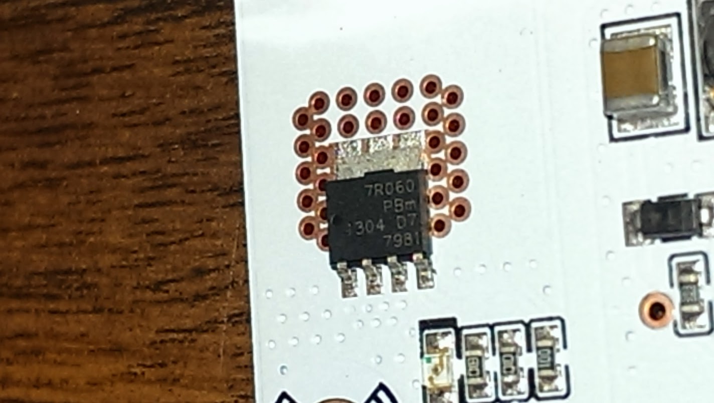
Here are some photos.


the PTC fuses are X16 GF1100 (16V 11A)

Here is the heated bed MOSFET 70-60 by NXP, doesn't look like a logic level gate input, I think I will replace that...
Message has been deleted
Travis Andrews
Dec 8, 2013, 1:40:12 PM12/8/13
to connected-commu...@googlegroups.com
I mean it should NOT be a clone! You can see the date on the sticker as 10/13.
The stepper drivers are all DRV8825 btw, based on the Pololu design apparently, but obviously not the exact same (the trimmers do have endstops though, unlike the Sainsmart drivers)
Luke Weston
Dec 9, 2013, 5:47:42 PM12/9/13
to connected-commu...@googlegroups.com
FYI the FET marked "7R060" is a PSMN7R0-60YS.
http://www.nxp.com/documents/data_sheet/PSMN7R0-60YS.pdf
http://www.nxp.com/documents/data_sheet/PSMN7R0-60YS.pdf
--
You received this message because you are subscribed to the Google Groups "Connected Community HackerSpace" group.
To unsubscribe from this group and stop receiving emails from it, send an email to connected-community-h...@googlegroups.com.
To post to this group, send an email to connected-commu...@googlegroups.com.
To view this discussion on the web, visit https://groups.google.com/d/msgid/connected-community-hackerspace/CAADMMbJ1FZE3OMufG071dmGk6XxX4%2BBg72VaM7MJu-iabh1M5g%40mail.gmail.com.
--
Travis Andrews
Dec 9, 2013, 6:10:52 PM12/9/13
to connected-commu...@googlegroups.com
yea I read that data sheet. Showed it to an electrical engineer here at work. He said it isn't a logic level gate input, and isn't necessarily ideal, but it does switch at 2V, so it should work with the 5V output from the Atmega 2560 chip, and should be good enough for 24V in this use (with a correct 24V heated bed).
To unsubscribe from this group and stop receiving emails from it, send an email to connected-community-hackerspace+unsubscribe@googlegroups.com.
To post to this group, send an email to connected-community-hacke...@googlegroups.com.
To view this discussion on the web, visit https://groups.google.com/d/msgid/connected-community-hackerspace/CAADMMbJ1FZE3OMufG071dmGk6XxX4%2BBg72VaM7MJu-iabh1M5g%40mail.gmail.com.
Michael Sullivan
Dec 9, 2013, 6:22:24 PM12/9/13
to connected-community-hackerspace
These stepper driver design is better then the polulu version as there is better heat dissipation and a greater surface area to mount the heat sinks
To view this discussion on the web, visit https://groups.google.com/d/msgid/connected-community-hackerspace/CAEPooQHYvm%2BbASgXTgcbozW_RGpREAVfSoNQq%3D3h4Du98MNj7A%40mail.gmail.com.
Bogdan Bednarczyk
Dec 9, 2013, 6:54:19 PM12/9/13
to connected-commu...@googlegroups.com
I thought that the one Travis have has more cooling area, the whole copper part is a cooling PAD?
you can still add more fins on the top is it is narrow enough to miss the trim potTo view this discussion on the web, visit https://groups.google.com/d/msgid/connected-community-hackerspace/CAB9i2Ban%3Dm_n-jAy5JOM_ER6MD0idrbJhMGpzm4c4zb2M%2B%3DDPQ%40mail.gmail.com.
--
Cheers
Bogdan
Clifford Heath
Dec 9, 2013, 8:01:31 PM12/9/13
to connected-commu...@googlegroups.com
On 10/12/2013, at 10:10 AM, Travis Andrews <lot...@gmail.com> wrote:
> yea I read that data sheet. Showed it to an electrical engineer here at work. He said it isn't a logic level gate input, and isn't necessarily ideal, but it does switch at 2V, so it should work with the 5V output from the Atmega 2560 chip, and should be good enough for 24V in this use (with a correct 24V heated bed).
> On Monday, December 9, 2013 3:47:42 PM UTC-7, Luke Weston wrote:
> FYI the FET marked "7R060" is a PSMN7R0-60YS.
>
> http://www.nxp.com/documents/data_sheet/PSMN7R0-60YS.pdf
Sorry, but your friend at work needs to learn how to read data sheets.
> yea I read that data sheet. Showed it to an electrical engineer here at work. He said it isn't a logic level gate input, and isn't necessarily ideal, but it does switch at 2V, so it should work with the 5V output from the Atmega 2560 chip, and should be good enough for 24V in this use (with a correct 24V heated bed).
> On Monday, December 9, 2013 3:47:42 PM UTC-7, Luke Weston wrote:
> FYI the FET marked "7R060" is a PSMN7R0-60YS.
>
> http://www.nxp.com/documents/data_sheet/PSMN7R0-60YS.pdf
Figure 6 shows that it clearly does NOT switch at 2V, even though section 6
shows Vgs(th) to have a *minimum* of 2V. The knee in the curve on Fig 6
is almost 4V, and I wouldn't regard the FET to be "on" until it reaches 4.5V.
Two facts from this data sheet are more relevant (than the threshold voltage)
to driving this FET from a microprocessor gate:
* Qg(tot) the total gate charge: 45nC (Vgs=10V, Vds=30V, close enough to 24V)
* Figure 8 shows that Rds(on) only reaches 7.5 mOhm at the full 5V, and is much
higher at 4.5V.
So, consider your microprocessor output pin. I have no idea what its output impedance
or maximum drive is, but it's common for these things to be >100ohm and <10mA.
Using this source impedance, you need to calculate the time required to charge the
gate to 4.5V. The effective gate capacitance is Cg is Q/V, specifically Qg(tot)/10,
which is 4.5nF. You need to charge this to 4.5V from a 5V source through 100 ohms.
The RC time constant here is then 0.45us (4.5nF*100R).
When you calculate the exponential curve, it takes 3.3 times the RC time constant
to reach 4.5V. One time constant gets you to about 0.7 of the source voltage, two
to 0.84, three to 0.89, and 3.3 to your 4.5v (90% of the 50V source). So it'll take
1.5us (3.3*0.45) for that output port to switch that FET.
During the switching time, the FET will have substantial current *and* voltage (i.e.
power dissipation). Take note that the impedance of your CPU pin may be different
in source (+5V) vs sink (0V) mode; it may pull up harder than it pulls down so you'll
have two different time constants.
Regardless, if you switch the FET at too high a frequency, you will overheat it.
I've used example numbers here, but you get the idea. The actual power dissipation
will depend on the Rds values while the gate is approaching the transition at 3.5V,
and you'd need to plot the area under the curve.
Or just use a buffer (aka gate driver) with a much lower output impedance, to reduce
the time constant. Bear in mind that switching too fast will create RF noise that you
will have to shield, snub, etc.
Here ends the MOSFET-driving lesson. You take the wheel now, and try not to
kangaroo-hop when you release the clutch.
Clifford Heath.
Darren Freeman
Dec 9, 2013, 10:17:25 PM12/9/13
to connected-commu...@googlegroups.com
On Tue, 2013-12-10 at 12:01 +1100, Clifford Heath wrote:
> On 10/12/2013, at 10:10 AM, Travis Andrews <lot...@gmail.com> wrote:
> > yea I read that data sheet. Showed it to an electrical engineer here at work. He said it isn't a logic level gate input, and isn't necessarily ideal, but it does switch at 2V, so it should work with the 5V output from the Atmega 2560 chip, and should be good enough for 24V in this use (with a correct 24V heated bed).
>
> > On Monday, December 9, 2013 3:47:42 PM UTC-7, Luke Weston wrote:
> > FYI the FET marked "7R060" is a PSMN7R0-60YS.
> >
> > http://www.nxp.com/documents/data_sheet/PSMN7R0-60YS.pdf
>
> Sorry, but your friend at work needs to learn how to read data sheets.
If you consider this in the context of the particular application,
> On 10/12/2013, at 10:10 AM, Travis Andrews <lot...@gmail.com> wrote:
> > yea I read that data sheet. Showed it to an electrical engineer here at work. He said it isn't a logic level gate input, and isn't necessarily ideal, but it does switch at 2V, so it should work with the 5V output from the Atmega 2560 chip, and should be good enough for 24V in this use (with a correct 24V heated bed).
>
> > On Monday, December 9, 2013 3:47:42 PM UTC-7, Luke Weston wrote:
> > FYI the FET marked "7R060" is a PSMN7R0-60YS.
> >
> > http://www.nxp.com/documents/data_sheet/PSMN7R0-60YS.pdf
>
> Sorry, but your friend at work needs to learn how to read data sheets.
although a competent person would never have specified this component,
it's passable.
Here's what I said earlier: "The ones on RUMBA are still borderline,
however, since they're not intended for a gate voltage of 5 V. Using the
PCB as a heat-sink, I'd expect them to get noticeably warm at 11 A, as
they would dissipate around 0.9 W to 1.2 W."
The range 0.9 W to 1.2 W is based on the data sheet and assuming between
PCB as a heat-sink, I'd expect them to get noticeably warm at 11 A, as
they would dissipate around 0.9 W to 1.2 W."
4.5 V and 5 V of static gate drive.
I can imagine a scenario where the gate drive goes below 4.5 V, such as
if you overload the 5 V regulator on the Arduino. Worst case dissipation
in the MOSFET is over 50 W under this scenario (at 24 V), so you will
smoke out your board. Hopefully this won't happen as you're not
experimenting with overloading your 5 V rail while attempting to print,
but most of us won't be thinking about this as we fiddle with the LCD
front panel which is driven from the 5 V rail. The back-light is 5V and
pulls a fair current.
If these parts were specified for cost reasons, they could have easily
built a 12 V gate drive circuit for a few cents more. Stuart Young is
doing this on his variant, and really it's the most sensible way to go.
I did this on the Prusa in the space. Requiring a MOSFET to be driven at
logic level is going to lead to compromises in its performance. Not even
using the right MOSFET is worse.
You want things to work reliably, not just most of the time.
> Regardless, if you switch the FET at too high a frequency, you will overheat it.
also you're switching 11 A without a free-wheeling current path - so it
may avalanche breakdown the MOSFET on every turn off. There are many
reasons why this circuit is only suitable for intermittent switching.
In this application, however, the firmware implements PWM at around 1
Hz, and it "works" albeit with excess heating. You do hear about failed
MOSFETs that fail shorted, and it's no surprise given that some of them
are dissipating a lot of power with fans blowing hard on them, and all
of them have no free-wheeling diode, snubbers, or any protection from
EMI and ESD from hitting the gate.
Combine the real possibility of a shorted MOSFET with the decision to
limit the power to the load by limiting the PWM duty cycle in firmware,
and you can see how easily this could lead to a fire.
Protection against excessive average currents is essential. Maybe you
want to pull 20 A during the initial warm-up, but under normal
circumstances it should reduce to 10 A after a few minutes, under
closed-loop control. Fine, so use a 15 A circuit breaker. That's what
they're for :)
Have fun,
Darren
Clifford Heath
Dec 10, 2013, 4:40:36 PM12/10/13
to connected-commu...@googlegroups.com
On 10/12/2013, at 2:17 PM, Darren Freeman <dar...@freemaninstruments.com> wrote:
> On Tue, 2013-12-10 at 12:01 +1100, Clifford Heath wrote:
>> Sorry, but your friend at work needs to learn how to read data sheets.
> If you consider this in the context of the particular application, it's passable.
> On Tue, 2013-12-10 at 12:01 +1100, Clifford Heath wrote:
>> Sorry, but your friend at work needs to learn how to read data sheets.
It was the "it does switch at 2V" that I objected to.
He was right to point out that it will sorta work though not ideal.
>> Regardless, if you switch the FET at too high a frequency, you will overheat it.
> Quite right, utterly useless in a PWM application beyond a few kHz. But
> also you're switching 11 A without a free-wheeling current path
For other's benefit, you can't suddenly stop current in an inductor.
It *will* find a path to deplete the stored magnetic energy, no matter
what voltage it has to create to force a path.
I hope someone found my post educational.
Clifford Heath.
Message has been deleted
Travis Andrews
Dec 10, 2013, 6:27:08 PM12/10/13
to connected-commu...@googlegroups.com
All good, and helpful info.
I may have misquoted my coworker, and also confused him by sending him another datasheet for a MOSFET with a logic level input at the same time. He was actually referring to the other MOSFET and not the NXP that comes on the RUMBA.
Darren Freeman
Dec 10, 2013, 10:08:05 PM12/10/13
to connected-commu...@googlegroups.com
On Wed, 2013-12-11 at 08:40 +1100, Clifford Heath wrote:
> >> Regardless, if you switch the FET at too high a frequency, you will overheat it.
> > Quite right, utterly useless in a PWM application beyond a few kHz. But
> > also you're switching 11 A without a free-wheeling current path
>
> Ouch. I hadn't looked at the circuit.
Understandable. You just don't expect to see things like this.
> >> Regardless, if you switch the FET at too high a frequency, you will overheat it.
> > Quite right, utterly useless in a PWM application beyond a few kHz. But
> > also you're switching 11 A without a free-wheeling current path
>
> Ouch. I hadn't looked at the circuit.
I gather that because they "work", people copy each other and chalk the
occasional failure down to bad luck or something they were doing wrong
at the time.
But a suitable Schottky diode, such as SS16 (1A / 60V), is $0.06 at
Element14, and it takes up hardly any real estate.
> For other's benefit, you can't suddenly stop current in an inductor.
> It *will* find a path to deplete the stored magnetic energy, no matter
> what voltage it has to create to force a path.
consists of a single serpentine track that sort of looks like a big blob
of twisted pair if you stand far enough back. It's the wiring to and
from the bed that could create excessive inductance if you don't twist
it. Of course I'm sure somebody has a heater that is wound like an ideal
inductor, too, and it would be nice if the circuit could handle the
general case. Maybe somebody hooks up a relay to that output instead -
now you have a 0.1 A load that can easily create a spark when you
suddenly cut the current.
We're not talking about a lot of inductance, but at 11 A you still store
a fair amount of energy. It has to go somewhere every time you interrupt
the current. It will go into charging the capacitance of the MOSFET, and
it will peak at a voltage that goes roughly with sqrt(L/C). If that's
enough to break down the MOSFET, then the energy will dissipate,
hopefully without lasting damage, but once it's below that voltage it
will still result in ringing at some fairly high frequency like a few
MHz, and it's doing so in a nice antenna circuit that will radiate some
of the energy as electromagnetic interference instead.
So whilst it sort of works at 1 Hz PWM, it's not very well engineered.
If you speed up the PWM you will increase the radiated EMI as well as
the power dissipation.
There is a reason for having a "right" way to do things. It hurts the
brain to have to think everything through every time, considering every
way that a user will wire something up. Always always always include a
free-wheeling diode.
I could mention that there's no RF supply decoupling in the vicinity of
these switches, too. So the sudden dI/dt transient is present to some
extent on the supply input too. But I think we've made our point that
the design needs polishing in ways that add hardly anything to the cost
or complexity. Let's not go on.
I'm thinking of maybe publishing my own revision, as it would be quicker
than talking about it. Perhaps you can look it over before it's
released, since there's always something that one person in isolation
will overlook.
Have fun,
Darren
Luke Weston
Dec 10, 2013, 11:12:29 PM12/10/13
to connected-commu...@googlegroups.com
I think some people have the idea that what they need to do is track down a certain model of exotic brand-X FET at a high cost, from the far corners of the world, install it onto an existing generic crappy RAMPS or whatever, and they'll be good to go reliably.
But it's not required that you spend $10 each on unobtanium FETs. The PSMN7R0-60YS or the RJK0452DPB cost about $1 each, and I think either of them would be examples of perfectly reliable, solid FETs for this application if used properly. (There are many other reasonable candidates, but we've mentioned those one already in this thread.) I don't think MOSFET selection of ~$1 FETs is itself a problem, they're good MOSFETs, but the way the rest of the circuit is implemented around them and the way the gate is driven directly from the AVR is a problem.Even if technically the threshold voltage is 4V or something that does *not* mean "it works at that voltage" in a high-power switching application... it's not good design practice... a high-power MOSFET switch should have its gate driven well above the threshold voltage, and it should be able to not only charge fast but also discharge fast.
And decent gate drive electronics in between the FET and the AVR costs, what, maybe $1 extra each?
Grafting gate driver circuits into an existing board is a little harder... but not impossible. If you're lucky there is probably a small resistor (say 10 ohm) on the board in between the AVR and the FET gate, and you could take that off the board and tap in there to the input and output of a gate driver.
Have fun,
Darren
--
You received this message because you are subscribed to the Google Groups "Connected Community HackerSpace" group.
To unsubscribe from this group and stop receiving emails from it, send an email to connected-community-h...@googlegroups.com.To view this discussion on the web, visit https://groups.google.com/d/msgid/connected-community-hackerspace/1386731285.12973.129.camel%40buffy.sunnydale.
To post to this group, send an email to connected-commu...@googlegroups.com.
For more options, visit https://groups.google.com/groups/opt_out.
Darren Freeman
Dec 11, 2013, 12:22:39 AM12/11/13
to connected-commu...@googlegroups.com
On Wed, 2013-12-11 at 15:12 +1100, Luke Weston wrote:
> Even if technically the threshold voltage is 4V or something that does
> *not* mean "it works at that voltage" in a high-power switching
> application... it's not good design practice... a high-power MOSFET
> switch should have its gate driven well above the threshold voltage,
> and it should be able to not only charge fast but also discharge fast.
I disagree on charging and discharging fast.
> Even if technically the threshold voltage is 4V or something that does
> *not* mean "it works at that voltage" in a high-power switching
> application... it's not good design practice... a high-power MOSFET
> switch should have its gate driven well above the threshold voltage,
> and it should be able to not only charge fast but also discharge fast.
In this application it would be preferable to switch a little slower to
limit the EMI. Say 10 us rise/fall time would limit the bandwidth to of
the order of 100 kHz for no measurable penalty in heating. (Under a mW
averaged over 1 Hz switching.)
A logic level device driven via a R/C filter is not out of the question
if that works out to be the
cheapest/simplest/most_reliable/insert_your_goal_here.
> If you've got an existing board which has got PSMN7R0s on it, for
> example, no need to go tearing them off the board and looking for
> replacements, IMO. (Unless they're actually damaged.) Add a flyback
> diode and gate driver to the existing MOSFET on the board and you
> should then have something that will work very reliably, solidly, at
> low added cost. Maybe the people who design these cheap things think
> that the MOSFET integral body diode can be relied upon for the
> freewheeling current? I dunno.
the body diode that breaks down to clamp the excessive voltages. And
technically they are usually rated for repeated avalanche capability,
which is nice when you have such fast transients that you can't snub
them completely, as in a SMPS. But the cost of a diode plus the
reliability that it buys you is a bit of a no-brainer. Drastically
reducing the EMI should not be seen as optional, either.
<Insert a statement to the effect that ham radio users have a right to
exist and that polluting the airwaves is against the law even if you
don't know that you're doing it.>
I would be happy to see a PSMN7R0 in a new design with a proper gate
driver, but for my time and money I'd buy the $1 logic level replacement
with the same package and pinout, and have someone in the space show me
how to use the air gun to cleanly replace it in record time.
This is where I'm happy with the people who sold me my Sanguinololu kit.
They knew enough to substitute better devices, and knowing this, I
didn't bother with the heat-sink. But most sellers assume that the
design makes sense to begin with. You get what you pay for, and my UK
seller wanted to distinguish themselves from the rest of the pack.
> You should be able to easily add a diode across existing screw
> terminals to the heater as a trivially easy job with a through-hole
> diode. No board modifications needed, you can use any existing board
> design. And you're spending what, 10 cents? As Darren said, the bed
> heater inductance is probably not high... but current is high enough
> that the dI/dt is large enough to be wary of.
a suitable diode:
Cat. ZR1020 - 1N5819 - 1A / 40V. $0.60 ea.
Should be suitable for up to 35 V input, and the low 20s of A load
current. Wire it up in parallel across the terminals going to your
heater, with anode going to NEGATIVE, i.e. reversed, so that no current
flows when the heater turns on. If you wire it up the wrong way it WILL
DEFINITELY EXPLODE.
> Grafting gate driver circuits into an existing board is a little
> harder... but not impossible. If you're lucky there is probably a
> small resistor (say 10 ohm) on the board in between the AVR and the
> FET gate, and you could take that off the board and tap in there to
> the input and output of a gate driver.
space, and it's pretty messy. You can't then add something else in that
location, nor easily work on it. Remember that a one-transistor
amplifier is inverting, so you need two of them if you want logic zero
to be "off". (I'm sure there's a chip for this, maybe an optoisolator,
but I used only what was in the space.)
A small daughter board would be well worth making for all the thousands
of units already fitted to printers. I was thinking it would be most
convenient to have the switch remotely mounted closer to the bed, so the
main board doesn't have to deal with high currents and voltage drops
across the wiring up to the board and back down again.
I had planned to do this on the printer in the space, but other issues
became more urgent. As is always the way. It highlights how important it
is to get it right in the first place before it becomes a work-horse
that you don't want to mess with until it dies unexpectedly because of
the thing you didn't end up fixing ;)
Have fun,
Darren

Jean Le Bouthillier
Mar 13, 2014, 9:43:47 PM3/13/14
to connected-commu...@googlegroups.com, dar...@freemaninstruments.com
Hi,
I would like to replace the PTC fuses with regular fuses. Can anyone point out an actual part with part number that would be suitable and fit onto the existing board?
Thanks
Darren Freeman
Mar 14, 2014, 12:07:12 AM3/14/14
to Jean Le Bouthillier, connected-commu...@googlegroups.com
On Thu, 2014-03-13 at 18:43 -0700, Jean Le Bouthillier wrote:
> I would like to replace the PTC fuses with regular fuses. Can anyone
> point out an actual part with part number that would be suitable and
> fit onto the existing board?
My earlier advice was to have some panel-mount fuses, and run wires to
> I would like to replace the PTC fuses with regular fuses. Can anyone
> point out an actual part with part number that would be suitable and
> fit onto the existing board?
the board. (You can make up a neat panel on the laser cutter.)
I wouldn't install a regular fuse directly onto the board without a
socket, as you will be very annoyed if/when you have to replace it. But
that's the way that would fit in the same space, as you can get fuses
that have axial leads, like regular resistors do.
You may be able to drill some extra holes to make M205 fuse clips fit in
roughly the same space, but that's not what you were asking for.
I can't think of any sockets that have the exact same shape. What you
might do is take the board to Jaycar, hold some sockets against the
board, pick the one that is closest, and then run some heavy stiff wire
from the socket to the board. I.e. some enamelled copper wire, normally
used for winding coils.
Have fun,
Darren

Lauren Shearer
Mar 15, 2014, 7:44:27 AM3/15/14
to connected-commu...@googlegroups.com, Jean Le Bouthillier, dar...@freemaninstruments.com
On Friday, 14 March 2014 15:07:12 UTC+11, Darren Freeman wrote:
On Thu, 2014-03-13 at 18:43 -0700, Jean Le Bouthillier wrote:
> I would like to replace the PTC fuses with regular fuses. Can anyone
> point out an actual part with part number that would be suitable and
> fit onto the existing board?
Unfortunately, no.
There are some surface mount blade fuse holders around, but not from the usual online or bricks-n-moartar crowds.
You can, however, get an "inline" fuse and solder nth ends onto the board. Jaycar stocks them in a "stackable" form which may fit.

Roger Kobler
Nov 13, 2014, 10:00:45 AM11/13/14
to connected-commu...@googlegroups.com, jea...@gmail.com, dar...@freemaninstruments.com
Am Samstag, 15. März 2014 12:44:27 UTC+1 schrieb Lauren Shearer:
On Friday, 14 March 2014 15:07:12 UTC+11, Darren Freeman wrote:On Thu, 2014-03-13 at 18:43 -0700, Jean Le Bouthillier wrote:
> I would like to replace the PTC fuses with regular fuses. Can anyone
> point out an actual part with part number that would be suitable and
> fit onto the existing board?
Hello
I found this thread and i have a question.
I hope someone can help me.
I have a Rumba board and use a 24V power supply.
I use stepperdriver 8825 and a steppermotor rated power 24-40v 1.8A.
After test (only 1 motor is connected on x-axes/port 1/stepperdriver 1) after 10 seconds the capacitor on port 2, placed under the stepperdriver 2 is blown up and shot the stepperdriver away...
but on this port/stepperdriver was nothing connected.
Is that a fault form factory or what I'm doing wrong?
Message has been deleted
Travis Andrews
Nov 13, 2014, 5:33:43 PM11/13/14
to connected-commu...@googlegroups.com, jea...@gmail.com, dar...@freemaninstruments.com
Can you post a photo of how you have the 8825 plugged into the Rumba on the first port?
Darren Freeman
Nov 18, 2014, 8:10:55 AM11/18/14
to connected-commu...@googlegroups.com, Roger Kobler
On Thu, 2014-11-13 at 07:00 -0800, Roger Kobler wrote:
> I have a Rumba board and use a 24V power supply.
> I use stepperdriver 8825 and a steppermotor rated power 24-40v 1.8A.
>
>
> After test (only 1 motor is connected on x-axes/port 1/stepperdriver
> 1) after 10 seconds the capacitor on port 2, placed under the
> stepperdriver 2 is blown up and shot the stepperdriver away...
> but on this port/stepperdriver was nothing connected.
There are only two likely reasons for this electrolytic capacitor to
> I have a Rumba board and use a 24V power supply.
> I use stepperdriver 8825 and a steppermotor rated power 24-40v 1.8A.
>
>
> After test (only 1 motor is connected on x-axes/port 1/stepperdriver
> 1) after 10 seconds the capacitor on port 2, placed under the
> stepperdriver 2 is blown up and shot the stepperdriver away...
> but on this port/stepperdriver was nothing connected.
explode 10s from initial power on.
1) Reverse polarity
2) Exceeded the voltage rating
This capacitor is fed from Vin1, and this input has a reverse protection
diode, although the diode is only 1 A, and the fuse is 5 A with a time
delay. The reverse protection diode would trip most power supplies with
short circuit protection, but if the supply keeps pushing current, then
the diode would be destroyed. So please, just check whether D6 looks
like it's also exploded.
Over-voltage - are you sure your power supply is only delivering 24 V?
That leaves the capacitor either soldered to the board in reverse, or
having an inadequate voltage rating. The schematic on reprap.org calls
for a 35 V capacitor.
My best guess is that you're looking at 16 V capacitors. The good news
is you can replace these capacitors and probably still use the board. If
the remaining capacitors are at least 25 V, then it's more likely that
this particular capacitor was soldered in backwards. Again, replace it
and you should be fine.
If it was the capacitor in reverse, or not the right voltage, then
clearly that's not your fault. (Unless you were told about the voltage
being different from the design.)
Have fun,
Darren
Reply all
Reply to author
Forward
0 new messages