
Sebastián Sáez
I'm trying to read temp with a ds18b20 sensor. I try with a few tutorial without luck.
Any tips for read this sensor?
I'm using Debian 8.6 2016-11-06 4GB SD SeeedStudio IoT (kernel 4.4.30-ti-r64)
regards,
Sebastián

Dennis Lee Bieber
On Wed, 30 Nov 2016 20:03:21 -0800 (PST), Sebastián Sáez
<otr...@gmail.com> declaimed the following:
>
>I want to read temp with a ds18b20 sensor. I try with a few tutorial
>without luck.
>
What does "without luck" mean?
Program aborts with segfault?
Program runs but reports unrealistic values?
Program hangs up -- and if it does, on what statement (sample of your
code would be useful, along with some description of how you have the
sensor wired).
--
Wulfraed Dennis Lee Bieber AF6VN
wlf...@ix.netcom.com HTTP://wlfraed.home.netcom.com/

acheesehead
Sebastián Sáez
/dts-v1/;/plugin/;/ {compatible = "ti,beaglebone", "ti,beaglebone-black";
part-number = "BB-W1";version = "00A0";/* state the resources this cape uses */exclusive-use =/* the pin header uses */
"P9.22",
/* the hardware IP uses */
"gpio0_2";
fragment@0 {target = <&am33xx_pinmux>;__overlay__ {dallas_w1_pins: pinmux_dallas_w1_pins {
pinctrl-single,pins = < 0x150 0x37 >;
};};};fragment@1 {target = <&ocp>;__overlay__ {onewire@0 {compatible = "w1-gpio";pinctrl-names = "default";pinctrl-0 = <&dallas_w1_pins>;status = "okay";
gpios = <&gpio1 2 0>;};};};};

William Hermans
exclusive-use =
/* the pin header uses */
"P9.22",
/* the hardware IP uses */
"gpio0_2";
should be:
exclusive-use =
/* the pin header uses */
"P9.22";
The comment is also wrong, but whatever, it shouldn't hurt anything.
Second:
fragment@1 {
               target = <&ocp>;
               __overlay__ {
               onewire@0 {
                   compatible      = "w1-gpio";
                   pinctrl-names   = "default";
                   pinctrl-0       = <&dallas_w1_pins>;
                   status          = "okay";

                   gpios = <&gpio1 2 0>;
               };
The code in bold is wrong. The gpio bank for this pin is bank0:
gpios = <&gpio0 2 0>; would be the correct assignment.
Lastly, your overlay "compatible" assignment is wrong for your board. It should look like this:

https://github.com/beagleboard/bb.org-overlays/blob/master/src/arm/BB-W1-P9.12-00A0.dts#L18
William Hermans
William Hermans
Hardware setup:
Everything is directly connected via jumper wires, with no additional components.
DS18B20 PIN1 connected to Beaglebone P9.1 (ground)
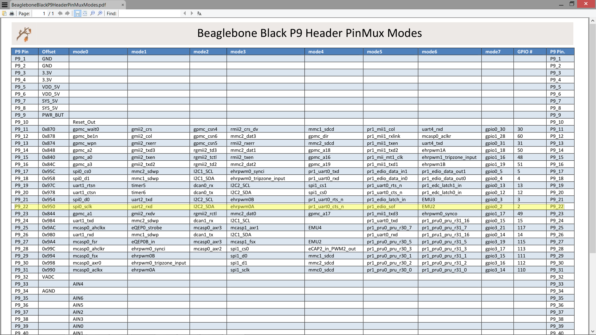
DS18B20 PIN2 connected to Beaglebone P9.22 (1-wire data)
DS18B20 PIN3 connected to Beaglebone P9.5 (Vdd 5v)
Remove any currently loaded overlays that might be using P9_22, then reboot.
Install git if need be:
william@beaglebone:~/dev$ sudo apt-get install git
git clone the bb.org-overlays repo:
william@beaglebone:~/dev$ git clone https://github.com/beagleboard/bb.org-overlays
Move into the source directory:
william@beaglebone:~/dev$ cd ./bb.org-overlays/src/arm
Find the file we're looking for:
william@beaglebone:~/dev/bb.org-overlays/src/arm$ ls |grep W1
BB-W1-P9.12-00A0.dts
Make a copy of the file while renaming it in one go:
william@beaglebone:~/dev/bb.org-overlays/src/arm$ cp BB-W1-P9.12-00A0.dts BB-W1-P9.22-00A0.dts
Edit copied 1-wire overlay source to suit our needs:
william@beaglebone:~/dev/bb.org-overlays/src/arm$ diff BB-W1-P9.12-00A0.dts BB-W1-P9.22-00A0.dts
4c4
< * Virtual cape for onewire on connector pin P9.12
---
> * Virtual cape for onewire on connector pin P9.22
21c21
< part-number = "BB-W1-P9.12";
---
> part-number = "BB-W1-P9.22";
27c27
< "P9.12";
---
> "P9.22";
35c35
< BONE_P9_12 0x37
---
> BONE_P9_22 0x37
51c51
< gpios = <&gpio1 28 GPIO_ACTIVE_HIGH>;
---
> gpios = <&gpio0 2 GPIO_ACTIVE_HIGH>;
Backout to the base path:
william@beaglebone:~/dev/bb.org-overlays/src/arm$ cd ../..
Build our newly created overlay:
william@beaglebone:~/dev/bb.org-overlays$ make ./src/arm/BB-W1-P9.22-00A0.dtbo
"Install" our overlay:
william@beaglebone:~/dev/bb.org-overlays$ sudo cp ./src/arm/BB-W1-P9.22-00A0.dtbo /lib/firmware/
Load our overlay:
william@beaglebone:~/dev/bb.org-overlays$ sudo sh -c "echo 'BB-W1-P9.22' > /sys/devices/platform/bone_capemgr/slots"
Check if the overlay loaded:
william@beaglebone:~/dev/bb.org-overlays$ cat /sys/devices/platform/bone_capemgr/slots
0: PF---- -1
1: PF---- -1
2: PF---- -1
3: PF---- -1
william@beaglebone:~/dev/bb.org-overlays$ dmesg |grep W1
[ 2826.626795] bone_capemgr bone_capemgr: part_number 'BB-W1-P9.22', version 'N/A'
[ 2826.626871] bone_capemgr bone_capemgr: slot #4: 'Override Board Name,00A0,Override Manuf,BB-W1-P9.22'
[ 2826.641278] bone_capemgr bone_capemgr: slot #4: dtbo 'BB-W1-P9.22-00A0.dtbo' loaded; overlay id #0
Check to make sure kernel modules loaded or not:
william@beaglebone:~/dev/bb.org-overlays$ lsmod |grep w1
w1_therm 4886 0
w1_gpio 3764 0
wire 35398 2 w1_gpio,w1_therm
Check sysfs:
william@beaglebone:~/dev/bb.org-overlays$ ls /sys/bus/w1/devices/
28-00000647ddf6 w1_bus_master1
Read from our sensor:
william@beaglebone:~/dev/bb.org-overlays$ cat /sys/bus/w1/devices/28-00000647ddf6/w1_slave
16 01 4b 46 7f ff 0a 10 98 : crc=98 YES
16 01 4b 46 7f ff 0a 10 98 t=17375
William Hermans
acheesehead
On Wednesday, November 30, 2016 at 8:58:19 PM UTC-7, Sebastián Sáez wrote:
William Hermans
In all of the examples that I have seen, the P9.x -> GPIO bank.port translates to GPIO (bank +1).port between lines in the overlay script.
William Hermans

TJF
Perhaps you're ready to test the libpruw1 project:
- pinmuxing handled by libpruio -> single source, just choose the bus pin in your source code (no device tree magic necessary)
- transparent bus input and output -> broadcast triggering of multiple sensors, fast readings
- monitoring feature -> watch what's going on at the bus @ 1MHz sampling rate (find interferences, sensor failures, ...)
Regards
Sebastián Sáez
Sebastián Sáez
acheesehead
Sebastián Sáez
root@beaglebone:/firmware# python test.py
Traceback (most recent call last):
File "test.py", line 4, in <module>
pir = mraa.Gpio(73)
File "/usr/lib/python2.7/dist-packages/mraa.py", line 912, in __init__
this = _mraa.new_Gpio(pin, owner, raw)
ValueError: Invalid GPIO pin specified
import mraa
import time
pir = mraa.Gpio(73)
pir.dir(mraa.DIR_IN)
while True:
print (pir.read())
time.sleep(1)
William Hermans
Thanks William. I'll try out your instructions on Mon.
william@beaglebone:~$ cat /etc/dogtag
BeagleBoard.org Debian Image 2016-10-30
william@beaglebone:~$ uname -r
4.4.27-ti-r62
So, someone mentioned in the last couple of days ( I think ) that they're using a 3.8.x kernel. A couple of concerns with this is that a) the overlays as described by me may not work the same. Meaning, I do not recall if 3.8.x overlays are slightly different or not. Through the source, or in how dtc compiles the source into "binaries". b) The sysfs file entries are possibly going to be different.
##BeagleBone Black: HDMI (Audio/Video) disabled:
dtb=am335x-boneblack-emmc-overlay.dtb
William Hermans
William Hermans
Dennis Lee Bieber
<yyr...@gmail.com> wrote:
>DS18B20 PIN1 connected to Beaglebone P9.1 (ground)
>DS18B20 PIN2 connected to Beaglebone P9.22 (1-wire data)
>DS18B20 PIN3 connected to Beaglebone P9.5 (Vdd 5v)
>
line, and I thought the BBB is supposed to only have 3.3V on the inputs.
William Hermans
Is that safe? I'd think the 5V would influence the swing of the data
line, and I thought the BBB is supposed to only have 3.3V on the inputs.
You know, it ran over night no problems, the sensor still working fine. I was however under the impression that I/O on the DQ pin was 3v3. Then my buddy saw your post and said " You know thats probably not good, I'm pretty sure there is no I/O regulation on the data pin . . ."
So yeah just goes to show when it comes to the physical aspects of electronics . . . I'm about good enough to be dangerous ;) In the future you see me talking about the physical characteristics of electronics . . .don't take my word on it ! I'm really not an EE.
Sebastián Sáez
William Hermans
Again, thanks Williams... that was it.I commented everything about P9.22 in ./bb.org-overlays/src/arm/univ-bbgw-00A0.dtsThen build and install with your instruccions :)Which is an elegant way to mount the w1 overlay automatically after reboot?
- write a script that's called by rc.local
- write a startup service, there are two ways to do this.
- create a one time at boot cron job.
In my mind, using Debian Jessie, creating a systemd service is the correct way to go about this. But in case that turns out to be too difficult, or cumbersome for your needs. Technically LSB sysv type services are also possible in Jessie. These are also rather hard to understand at first too. So writing a script, and then calling it from rc.local is probably the easiest way - Initially.
Cron jobs, in my mind are not really the right way to go. Because again, in my mind, cron jobs are meant to run something repeatable. Meaning running something multiple times. Once a day at a specific time, Once every hour, minute, whatever you like. However, it is possible to run a cron job once every reboot. . . .
I would however recommend that you read up on systemd services, and use that method.
William Hermans
william@beaglebone:~$ cat /boot/uEnv.txt |grep cape
#cmdline=coherent_pool=1M quiet cape_universal=enable video=HDMI-A-1:1024x768@60e
#cape_disable=capemgr.disable_partno=
#cape_enable=capemgr.enable_partno=
#cape_disable=bone_capemgr.disable_partno=
cape_enable=capemgr.enable_partno=<overlay_name> is the way to go. You can assign multiple cape overlays with this feature, but I do not remember if they are space, or comma separated. I'm thinking comma separated, but may be wrong.
Copy all your required overlays into /lib/firmware, which you've probably already done.
william@beaglebone:~$ cd /opt/scripts/
william@beaglebone:/opt/scripts$ git pull
william@beaglebone:/opt/scripts$ cd tools/developers/
william@beaglebone:/opt/scripts/tools/developers$ sudo ./update_initrd.sh
William Hermans
william@beaglebone:~$ diff ./dev/bb.org-overlays/src/arm/BB-W1-P8.14-00A0.dts ./dev/bb.org-overlays/src/arm/BB-W1-P9.12-00A0.dts
1c1,2
< /*
---
>
> /*
4c5
< * Virtual cape for onewire on connector pin P8.14
---
> * Virtual cape for onewire on connector pin P9.12
21c22
< part-number = "BB-W1-P8.14";
---
> part-number = "BB-W1-P9.12";
27c28
< "P8.14";
---
> "P9.12";
35c36
< BONE_P8_14 0x37
---
> BONE_P9_12 0x37
51c52
< gpios = <&gpio0 26 GPIO_ACTIVE_HIGH>;
---
> gpios = <&gpio1 28 GPIO_ACTIVE_HIGH>;
William Hermans
william@beaglebone:~/dev/bb.org-overlays$ diff src/arm/BB-W1-P8.26-00A0.dts src/arm/BB-W1-P8.14-00A0.dts
4c4
< * Virtual cape for onewire on connector pin P8.26
---
> * Virtual cape for onewire on connector pin P8.14
21c21
< part-number = "BB-W1-P8.26";
---
> part-number = "BB-W1-P8.14";
27c27
< "P8.26";
---
> "P8.14";
35c35
< BONE_P8_26 0x37
---
> BONE_P8_14 0x37
51c51
< gpios = <&gpio1 29 GPIO_ACTIVE_HIGH>;
---
> gpios = <&gpio0 26 GPIO_ACTIVE_HIGH>;
william@beaglebone:~/dev/bb.org-overlays$ make ./src/arm/BB-W1-P8.26-00A0.dtbo
DTC src/arm/BB-W1-P8.26-00A0.dtbo
william@beaglebone:~/dev/bb.org-overlays$ sudo cp ./src/arm/BB-W1-P8.26-00A0.dtbo /lib/firmware/
william@beaglebone:~/dev/bb.org-overlays$ cat /sys/devices/platform/bone_capemgr/slots
0: PF---- -1
1: PF---- -1
2: PF---- -1
3: PF---- -1
william@beaglebone:~/dev/bb.org-overlays$ cat /sys/devices/platform/bone_capemgr/slots
0: PF---- -1
1: PF---- -1
2: PF---- -1
3: PF---- -1
william@beaglebone:~/dev/bb.org-overlays$ dmesg |grep W1
[ 210.416276] bone_capemgr bone_capemgr: slot #4: 'Override Board Name,00A0,Override Manuf,BB-W1-P8.26'
[ 210.430251] bone_capemgr bone_capemgr: slot #4: dtbo 'BB-W1-P8.26-00A0.dtbo' loaded; overlay id #0
william@beaglebone:~/dev/bb.org-overlays$ ls /sys/bus/w1/devices/
28-00000647ddf6 w1_bus_master1
19 01 4b 46 7f ff 07 10 eb : crc=eb YES
19 01 4b 46 7f ff 07 10 eb t=17562
acheesehead
William Hermans
Tried your workflow today without success. Everything is OK up to the lsmod | grep w1 step. I only get the w1_gpio entry. I am not a Linux kernel expert, so I don't know how to troubleshoot why the other entries aren't showing up.I didn't see any activity on the oscilloscope either.
william@beaglebone:~/dev/bb.org-overlays$ lsmod |grep w1
w1_therm 4886 0
w1_gpio 3764 0
wire 35398 2 w1_gpio,w1_therm
william@beaglebone:~$ ls /sys/bus/w1/devices/
28-00000647ddf6 w1_bus_master1
william@beaglebone:~$ ls /sys/devices/platform/ocp
40300000.ocmcram 48042000.timer 480ca000.spinlock 49800000.tptc driver_override
40302000.ocmcram_nocache 48044000.timer 4819c000.i2c 49900000.tptc modalias
44e07000.gpio 48046000.timer 481ac000.gpio 49a00000.tptc ocp:l4_wkup@44c00000
44e09000.serial 48048000.timer 481ae000.gpio 4a100000.ethernet of_node
44e0b000.i2c 4804a000.timer 481d8000.mmc 4c000000.emif power
44e35000.wdt 4804c000.gpio 48200000.interrupt-controller 53100000.sham subsystem
44e3e000.rtc 48060000.mmc 48310000.rng 53500000.aes uevent
47400000.usb 480c8000.mailbox 49000000.edma 56000000.sgx
william@beaglebone:~$ ls /sys/devices/platform/ocp/44e07000.gpio/gpio/
gpiochip0
William Hermans
william@beaglebone:~$ ls /sys/devices/platform/ocp/*.gpio/gpio/
/sys/devices/platform/ocp/44e07000.gpio/gpio/:
gpiochip0
/sys/devices/platform/ocp/4804c000.gpio/gpio/:
gpiochip32
/sys/devices/platform/ocp/481ac000.gpio/gpio/:
gpiochip64
/sys/devices/platform/ocp/481ae000.gpio/gpio/:
gpiochip96
You wont get an actual gpio bank number. Just the bank offset. So going by this beaglebone blogpost: http://www.bonebrews.com/temperature-monitoring-with-the-ds18b20-on-a-beaglebone-black/
gpios = <&gpio2 13 0>; /* P8.11*/