CoreXYZ

Ryan Carlyle


Gary Crowell

Ryan Carlyle

Dan Newman
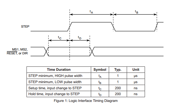
> I had gotten as far as a truth table and "most of" the gate schematic.
> (Just another iPad sketch.) But it's been about 10 years since I've done
> any gate-level logic design and I've forgotten how to most of it. So I was
> looking at something like, ehh, 10 ANDs, 5 ORs, and 12 inverters.
simplification. But looks like Gary did a mental equivalent.
Dan

Joseph Chiu
To view this discussion on the web visit https://groups.google.com/d/msgid/3dp-ideas/53D56AD3.80601%40mtbaldy.us.
--
You received this message because you are subscribed to the Google Groups "3DP Ideas" group.
To unsubscribe from this group and stop receiving emails from it, send an email to 3dp-ideas+unsubscribe@googlegroups.com.
To post to this group, send email to 3dp-...@googlegroups.com.
Gary Crowell
To unsubscribe from this group and stop receiving emails from it, send an email to 3dp-ideas+...@googlegroups.com.
To view this discussion on the web visit https://groups.google.com/d/msgid/3dp-ideas/CAL5_QBMPYes8%2B2RT5bWk869PPSq4_XX%3DeHe6BzVM4pfKO4mSFw%40mail.gmail.com.
Gary Crowell
Joseph Chiu
To view this discussion on the web visit https://groups.google.com/d/msgid/3dp-ideas/CAB%2B-abtqHv2T74f_%3DsMEDvRA0AWVbVikL5H31T6wUm8i9Fe7Fw%40mail.gmail.com.
Joseph Chiu
Gary Crowell
On Sunday, June 29, 2014 5:00:53 PM UTC-6, Ryan Carlyle wrote:
Design in progress.
Ryan Carlyle
How would you feel about putting 4x stepper driver sockets on there, with pass-throughs from a ribbon cable to the existing mightyboard sockets for vref, etc? I can connect everything manually if you don't feel like doing that much work, but it'd be nice. Hmm. Adding another driver's worth of current probably justifies running dedicated wiring to the PSU for the sub-board. Lemme sketch something up.
I had back-burnered the CoreXYZ build due to wife aggro on 3DP parts purchases, plus the overall difficult implementation scope. So I've been tweaking/upgrading my CoreXY and gradually accumulating parts for a third bot. But if you're helping on the electrical design, I can get back on CoreXYZ and perhaps strip my CoreXY for the frame and electronics. Wouldn't take a lot of extra non-printed parts -- just the spectra line drive, some more rods, etc. Plenty of parts design to do but that's not difficult. Hard part has always been getting the stepper control sorted.
Ryan Carlyle
Gary Crowell
Err, 34 channels!
To view this discussion on the web visit https://groups.google.com/d/msgid/3dp-ideas/CAL5_QBMPYes8%2B2RT5bWk869PPSq4_XX%3DeHe6BzVM4pfKO4mSFw%40mail.gmail.com.
--
You received this message because you are subscribed to the Google Groups "3DP Ideas" group.
To unsubscribe from this group and stop receiving emails from it, send an email to 3dp-ideas+unsubscribe@googlegroups.com.
To post to this group, send email to 3dp-...@googlegroups.com.
Joseph Chiu
To unsubscribe from this group and stop receiving emails from it, send an email to 3dp-ideas+...@googlegroups.com.
To view this discussion on the web visit https://groups.google.com/d/msgid/3dp-ideas/fafc1359-de21-4198-99f3-727cd158c1d2%40googlegroups.com.
Ryan Carlyle
One thing I haven't sorted out yet is how to do the spectra drive. For the first rev, I'll probably just print smooth pulleys and use fisherman's knots to make loops that can roll over grooved pulleys without issues. Maybe steal some Tantillus/Ingentis parts.
Ryan Carlyle
Yes, this is an issue with CoreXYZ too. The X,Y,Z resolutions are necessarily equal. And the Atmega is very limited on clock cycles to handle high steps/sec rates. So fast XY motion means rough Z resolution, and high Z resolution means slow XY motion. I haven't worked through all the implications of doing a "gear reduction" for CoreXY. It should be easy enough to put a loop in the Z-legs to give them a 3:1 mechanical advantage relative to XY, but I haven't worked through all the possible implications of that. (It should tilt the planes defined by each belt from 45 degrees to 15 degrees or something like that.)
One alternative that crossed my mind is using the stepper multiplexer circuit to double-step on XY moves and single-step on Z moves. That doesn't actually increase the Z resolution but it does reduce the processing load on the Atmega to fire the stepper interrupt for X and Y, which means on net the total XYZ resolution can be made finer. Same basic outcome. I think I'll build the symmetrical version first to see if it performs ok as-is, then try the 3:1 Z, and then save the electric fix as a last resort.

Vernon Barry
Ryan Carlyle
I'd love a system that changed the microstepping level depending on which direction it was stepping, but (didn't you tell me this?) the drivers lose microstep position registration when switching stepping levels. So the shortcut is double-stepping X and Y to make effective 1/8th stepping. Or just use the gantry pulleys.
Ryan Carlyle
I'll start modeling up the motion mechanism parts over the weekend. There's actually only a few CoreXYZ-specific parts to model -- the carriage, the X ends, and the Y ends mainly, then a few angled pulley mounts to attach stationary pulleys to the 2020 frame. Should be pretty easy.
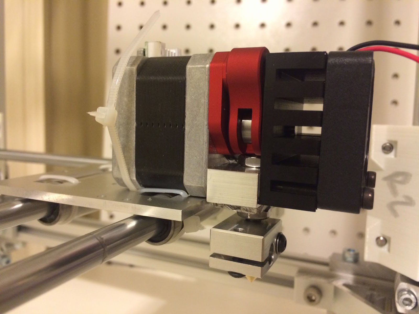
Most everything aside from the motion mechanism is just going to copy my CoreXY bot. HBP, electronics, extruder, etc all the same.
Ryan Carlyle
Ryan Carlyle

Ryan Carlyle

Gary Crowell
- I've got a breakout board for the MIghtyboard Botstep sockets - it uses a 10-pin header/cable to bring the signals to the converter board (I've got a bunch of 10-pin cables here somewhere).
- I added step select jumpers for AB, and CD.
- There are jumpers to reverse any ABCD direction.
- Sockets to mount the ABCD Botsteps.
- Mightyboard-type Molex 0.156x4 headers for motor connection.
- On-board 5V generated from 24V.
--
You received this message because you are subscribed to the Google Groups "3DP Ideas" group.
To unsubscribe from this group and stop receiving emails from it, send an email to 3dp-ideas+...@googlegroups.com.
To post to this group, send email to 3dp-...@googlegroups.com.
To view this discussion on the web visit https://groups.google.com/d/msgid/3dp-ideas/e52a141a-8d77-41ab-a684-2eaf013edbf2%40googlegroups.com.
Ryan Carlyle
- The step select jumpers are great. Caveat is that I think all the drivers have to be at the same microstepping level. If you put two drivers at 1/8th and two at 1/16th, motion won't be Cartesian any more. So you probably ought to use the same pair of jumpers for all four motors rather than breaking out two separate pairs. (Just dummy-proofs it a little.)
- Is there any risk from having two different 5v regulators in the system? Versus pulling the main 5v leg off a board driver socket. IE someone connects the two 5v legs together somehow. Not sure how the risk tradeoff here plays out since the board 5v is under-spec'd on the older hardware. I don't have the answer, just asking the question.
- The direction reversal jumpers are a really good addition. (Much easier than rewiring the steppers.) And now that you have those jumpers, you have the option to simplify the stepper header traces. Specifically where OUT1B and OUT1A cross to go to stepper header pins 3 and 4. If you de-cross that wiring, it will flip the stepper direction. Then the direction jumpers will flip it back.
- I don't think it matters in the slightest to the function, but the OUT1 and OUT2 phases are reversed against header pin numbers 1,2 and 3,4 compared to the Rev E Mightyboard. You have OUT2=1,2 whereas MBI has OUT2=3,4. Again, doesn't hurt anything, but I figured I'd mention it in case you're picky about consistency. Yeah, this is kind of the opposite of the last bullet, I know.
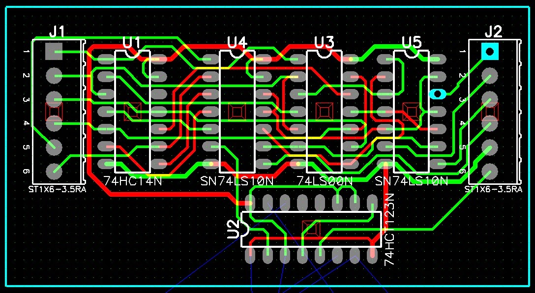
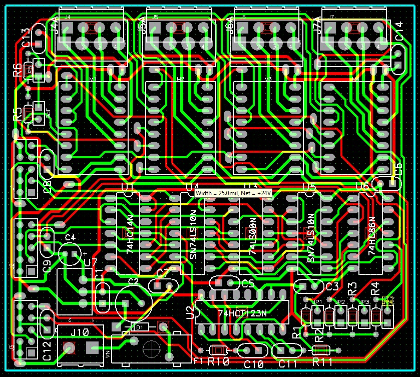
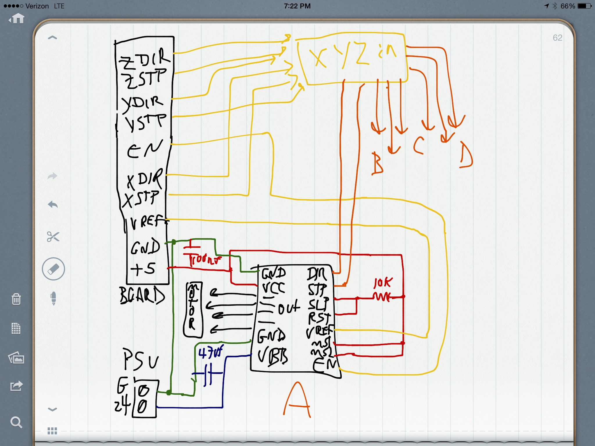
Looking really interesting.Here's the schematic for the XYZ-ABCD converter board.
- I've got a breakout board for the MIghtyboard Botstep sockets - it uses a 10-pin header/cable to bring the signals to the converter board (I've got a bunch of 10-pin cables here somewhere).
- I added step select jumpers for AB, and CD.
- There are jumpers to reverse any ABCD direction.
- Sockets to mount the ABCD Botsteps.
- Mightyboard-type Molex 0.156x4 headers for motor connection.
- On-board 5V generated from 24V.
I have the board routed except for a few impossible routes and some cleanup. Not too late to make changes though, if you have any other ideas.Gary
On Sat, Aug 2, 2014 at 10:02 PM, Ryan Carlyle <temp...@gmail.com> wrote:
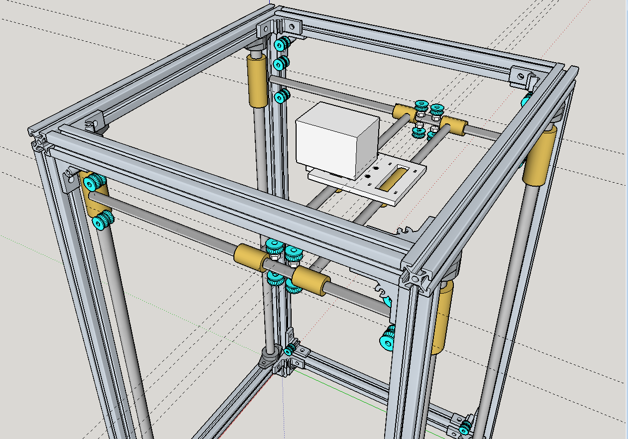
Motor arrangement, tensioning, and tramming sorted:
(the idlers on the 2020 rails near the motors will be "loosen, slide, tighten" to adjust line tension)
--
You received this message because you are subscribed to the Google Groups "3DP Ideas" group.
To unsubscribe from this group and stop receiving emails from it, send an email to 3dp-ideas+unsubscribe@googlegroups.com.
To view this discussion on the web visit https://groups.google.com/d/msgid/3dp-ideas/e52a141a-8d77-41ab-a684-2eaf013edbf2%40googlegroups.com.
Ryan Carlyle
- Misumi 2020 frame 340x340x580 to match my existing CoreXY lasercut parts, but size is very flexible. Main thing is the corner bracket style. The Y-end alignment and pulley size match Misumi HFS5 brackets since I'm using them to hold the Z pulleys. It could be modified for another bracket style or for a printed corner bracket without too much trouble.
- 12mm linear rods on Z, mounted with VXB shaft end flanges. Wouldn't be too hard to redesign for supported rod or extrusion slide.
- 8mm linear rods on X and Y
- These V-groove pulleys from Robotdigg: (need 52 = 9 sets) http://robotdigg.com/product/72/Fishing-Line-Pulley-Bearing
- Pretty much all M4 hardware
Ryan Carlyle
- Extruder carriage in its entirety
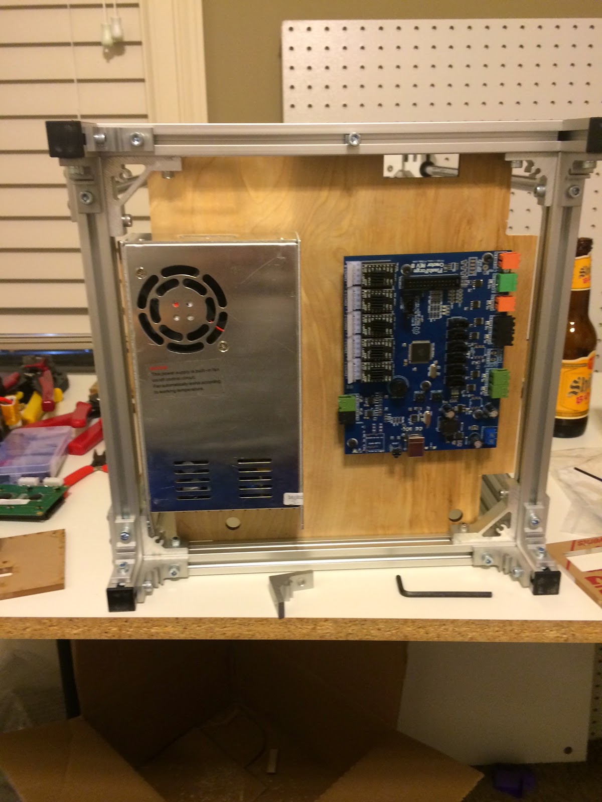
- All the electronics
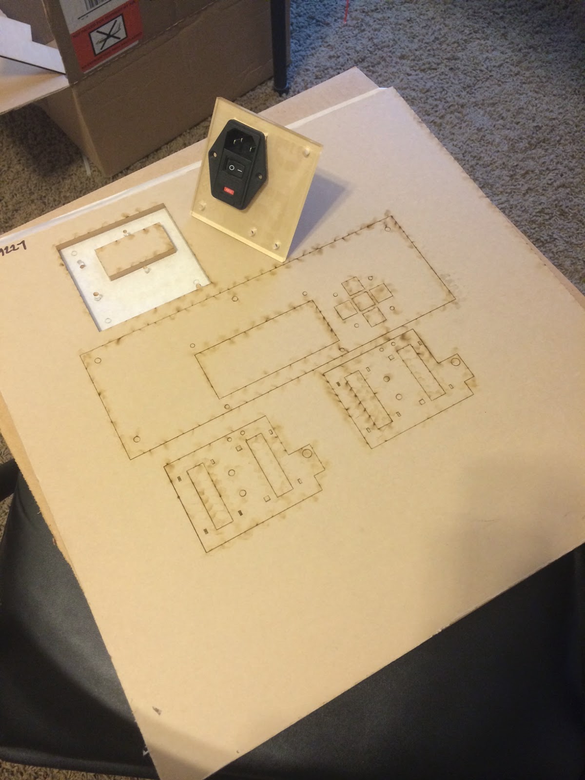
- Lasercut panels to hold electronics
Gary Crowell

--
You received this message because you are subscribed to the Google Groups "3DP Ideas" group.
To unsubscribe from this group and stop receiving emails from it, send an email to 3dp-ideas+...@googlegroups.com.
To post to this group, send email to 3dp-...@googlegroups.com.
To view this discussion on the web visit https://groups.google.com/d/msgid/3dp-ideas/bdc6e7a0-2a5a-48b0-86e0-8f67ad2cc09a%40googlegroups.com.
Vernon Barry
To view this discussion on the web visit https://groups.google.com/d/msgid/3dp-ideas/CAB%2B-abu4mh%3DB31%3DLah3ucnETmJ_yA9hvK%2BSZkxspoTs_cn61dw%40mail.gmail.com.
Ryan Carlyle
On Monday, August 4, 2014 8:09:13 AM UTC-5, Vernon Barry wrote:
Gary, I'm glad youa re doing this as a routed board, FYI James Armstrong who is also here in Charleston also has a PCB mill and can cut these for me as well.Sorry, that I've been quiet on this thread, just trying to get a few other major projects done in the very limited spare time that I have free right now.
On Sun, Aug 3, 2014 at 6:12 PM, Gary Crowell <garyacr...@gmail.com> wrote:
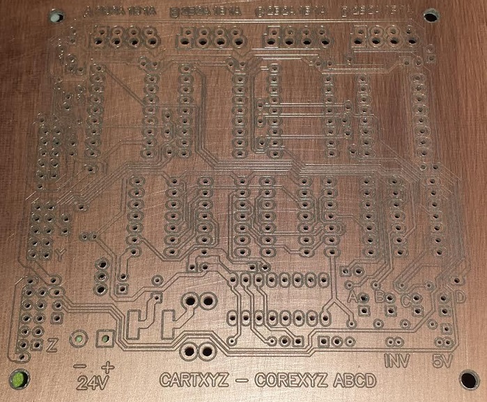
Current layout for the ABCD converter. 100% routed, even passed DRC for clearance. I'll still be tweaking for awhile to shorten traces and increase spaces where possible. Trying to get a better grid on the 5V/Gnd but I think it's about as good as it's gonna get. Layout may look odd in some respects 'cause it's done for a milled board. There's no thru vias except where a component pin or added wire goes thru the hole (and that pin must be soldered both sides). You can't put a topside trace to a component pin where the body of the component covers the pad (connectors, headers, etc.) 'cause you can't solder the topside on those. The body of the screwterm stepper output overlaps the molex connectors, so that's an either-or case.
On Sun, Aug 3, 2014 at 2:24 PM, Ryan Carlyle <temp...@gmail.com> wrote:
Lots of parts are coming directly from my CoreXY Cube build. Find the BOM for that here: http://www.thingiverse.com/thing:393155
- Extruder carriage in its entirety
- All the electronics
- Lasercut panels to hold electronics
--
You received this message because you are subscribed to the Google Groups "3DP Ideas" group.
To unsubscribe from this group and stop receiving emails from it, send an email to 3dp-ideas+unsubscribe@googlegroups.com.
To view this discussion on the web visit https://groups.google.com/d/msgid/3dp-ideas/bdc6e7a0-2a5a-48b0-86e0-8f67ad2cc09a%40googlegroups.com.
--
You received this message because you are subscribed to the Google Groups "3DP Ideas" group.
To unsubscribe from this group and stop receiving emails from it, send an email to 3dp-ideas+unsubscribe@googlegroups.com.
Vernon Barry
To unsubscribe from this group and stop receiving emails from it, send an email to 3dp-ideas+...@googlegroups.com.
To view this discussion on the web visit https://groups.google.com/d/msgid/3dp-ideas/07ef43dd-567c-48e1-aabf-63f43445aa0e%40googlegroups.com.

Chris P
Ryan Carlyle
Plus yeah, spectra drive is WAY cheaper with this many idlers.
Ryan Carlyle
On Sunday, August 3, 2014 5:12:45 PM UTC-5, Gary Crowell wrote:
Current layout for the ABCD converter. 100% routed, even passed DRC for clearance. I'll still be tweaking for awhile to shorten traces and increase spaces where possible. Trying to get a better grid on the 5V/Gnd but I think it's about as good as it's gonna get. Layout may look odd in some respects 'cause it's done for a milled board. There's no thru vias except where a component pin or added wire goes thru the hole (and that pin must be soldered both sides). You can't put a topside trace to a component pin where the body of the component covers the pad (connectors, headers, etc.) 'cause you can't solder the topside on those. The body of the screwterm stepper output overlaps the molex connectors, so that's an either-or case.

On Sun, Aug 3, 2014 at 2:24 PM, Ryan Carlyle <temp...@gmail.com> wrote:
Lots of parts are coming directly from my CoreXY Cube build. Find the BOM for that here: http://www.thingiverse.com/thing:393155
- Extruder carriage in its entirety
- All the electronics
- Lasercut panels to hold electronics
--
You received this message because you are subscribed to the Google Groups "3DP Ideas" group.
To unsubscribe from this group and stop receiving emails from it, send an email to 3dp-ideas+unsubscribe@googlegroups.com.
To view this discussion on the web visit https://groups.google.com/d/msgid/3dp-ideas/bdc6e7a0-2a5a-48b0-86e0-8f67ad2cc09a%40googlegroups.com.
Ryan Carlyle
Ryan Carlyle
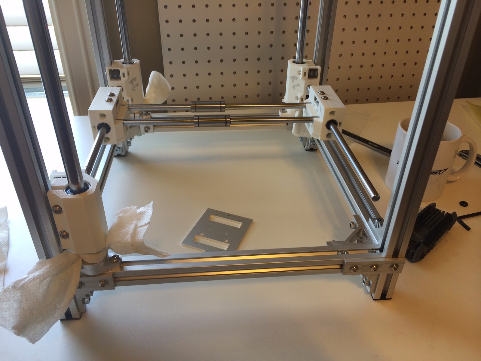
Frame kit
Electronics (FF mightyboard etc, PSU)
Linear rods and bearings
Spectra line
Stepper line pulleys
Most of the spectra idlers
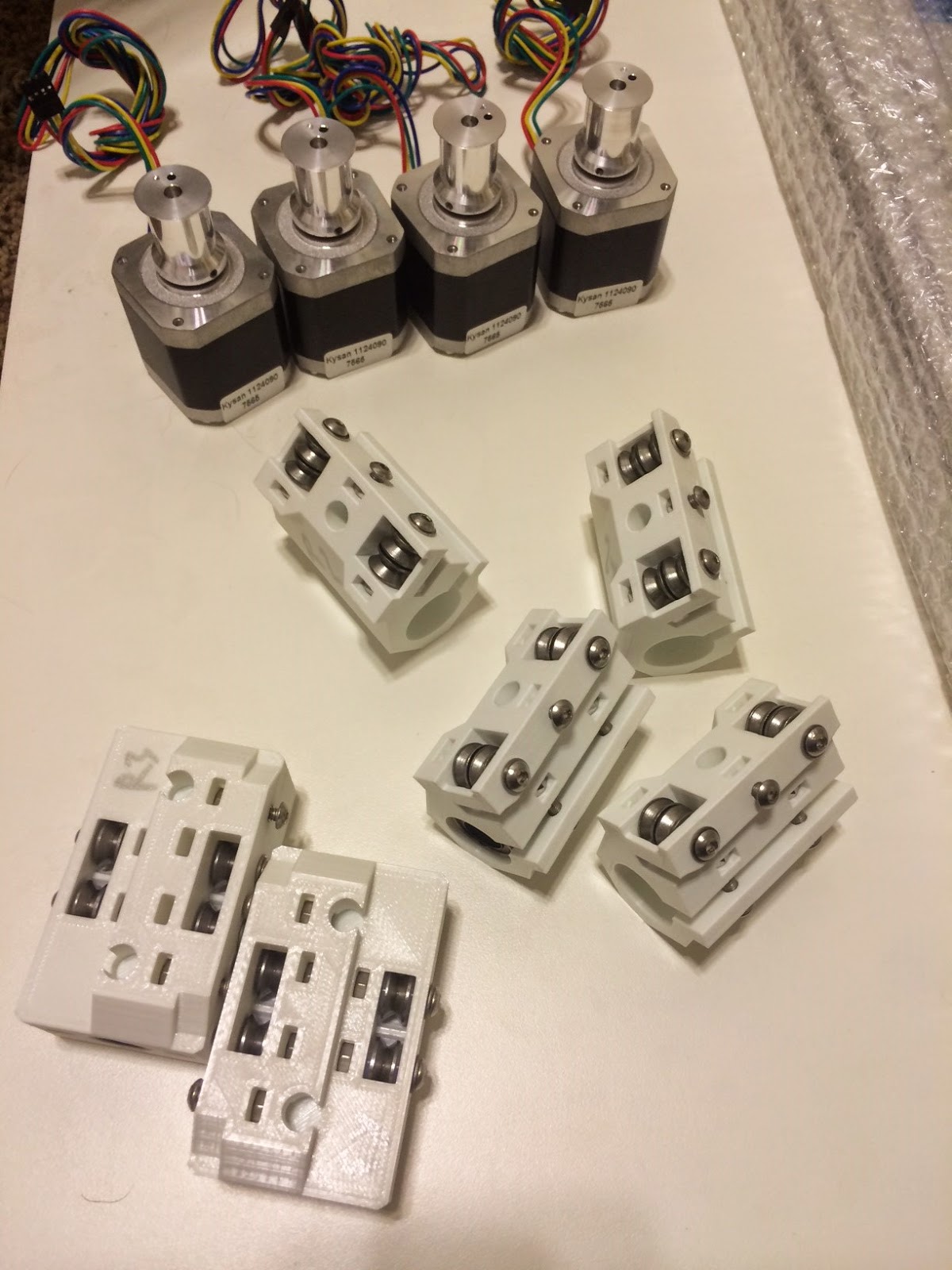
Steppers
Most of the printed parts (all the gantry components)
Extruder & hot end
Tons of M4 hardware
On the way / in progress:
Lasercut structure plates
More spectra idlers
HBP
Gary's kick-ass stepper multiplexing board
Some more printed parts (stepper brackets)
Hoping to get the frame and 3-axis gantry put together this weekend.
Ryan Carlyle
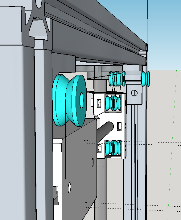
Latest render. Changed the motor arrangement and line path around to make mounting the HBP and electronics easier. It's not super pretty, but it's the least-bad routing I've come up with (of like five different options).

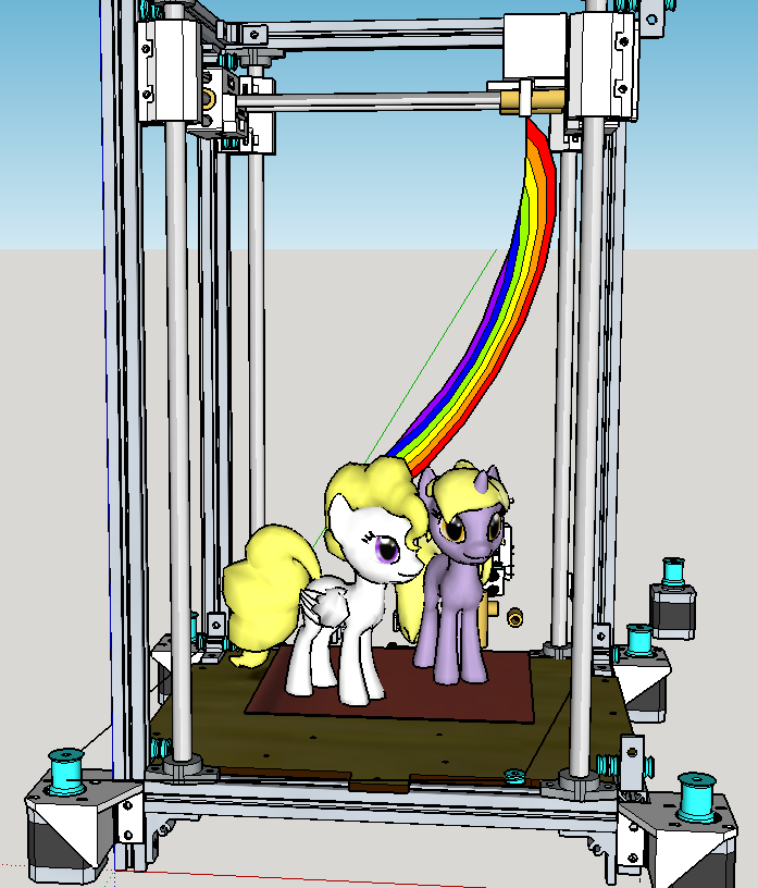
Dan Newman
>
>
> Latest render. Changed the motor arrangement and line path around to make
> mounting the HBP and electronics easier. It's not super pretty, but it's
> the least-bad routing I've come up with (of like five different options).
three stepper motors ;) (Also, I want to see rainbows shooting out of the extruder
and maybe a my little pony on the build plate. You know, to appeal to the bronies.)
Dan
Ryan Carlyle
Dan Newman
> Ask and ye shall receive.
>
> Friendship is magic!
Now that's a serious printer. Sign me up!
(P.S. we're they printed without support?)
Dan
Ryan Carlyle
Ryan Carlyle


Christopher Matthes
Ryan Carlyle
Chris P
Ryan Carlyle
Ryan Carlyle


Joseph Chiu
--
You received this message because you are subscribed to the Google Groups "3DP Ideas" group.
To unsubscribe from this group and stop receiving emails from it, send an email to 3dp-ideas+...@googlegroups.com.
To view this discussion on the web visit https://groups.google.com/d/msgid/3dp-ideas/5d2282d1-8057-44a6-8745-c90b7f1b5e91%40googlegroups.com.
Ryan Carlyle
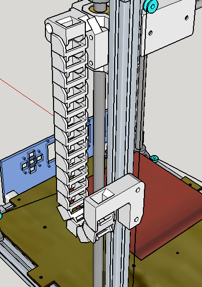
BUT, it's occurred to me that I have no idea how I'm going to run the wiring and filament feed tube. I built this thing for a 400mm tall build volume, and with the gantry moving up and down, that means I either need a ~800mm long overhead U-loop (ulgh) or some kind of clever routing solution that attaches to the moving gantry itself. Need some more thought on that one.
Ryan Carlyle


James Armstrong
Dan Newman
> Can't wait to see how it all works. I just picked up my Dan's special alum
> carriage from Jetguy (Vernon) Saturday. It is so much better than the
> acrylic one we originally did. Thanks Dan.
Only 2 mm thick Al plate so as to accomodate the thin jam nut trick. And it
is double slotted so you can do the old Mk7 mounting method. One of thoe
plates is used in this picture,
https://www.flickr.com/photos/d-newman/14628705904/in/set-72157645313526624/lightbox/
Dan
Ryan Carlyle


Ryan Carlyle
Christopher Matthes
Gary Crowell
Stumbled across this : http://forums.reprap.org/read.php?2,377858,page=1 thought you might find it interesting ;) It starts with a coreXZ and in the end they think about building the bot you already designed.How are you getting on with your corexyz ? Any news ?
--
You received this message because you are subscribed to the Google Groups "3DP Ideas" group.
To unsubscribe from this group and stop receiving emails from it, send an email to 3dp-ideas+...@googlegroups.com.
To post to this group, send email to 3dp-...@googlegroups.com.
To view this discussion on the web visit https://groups.google.com/d/msgid/3dp-ideas/61c45ce6-8f50-4f2f-8bf5-0d68d797b36e%40googlegroups.com.
Ryan Carlyle
Ryan Carlyle


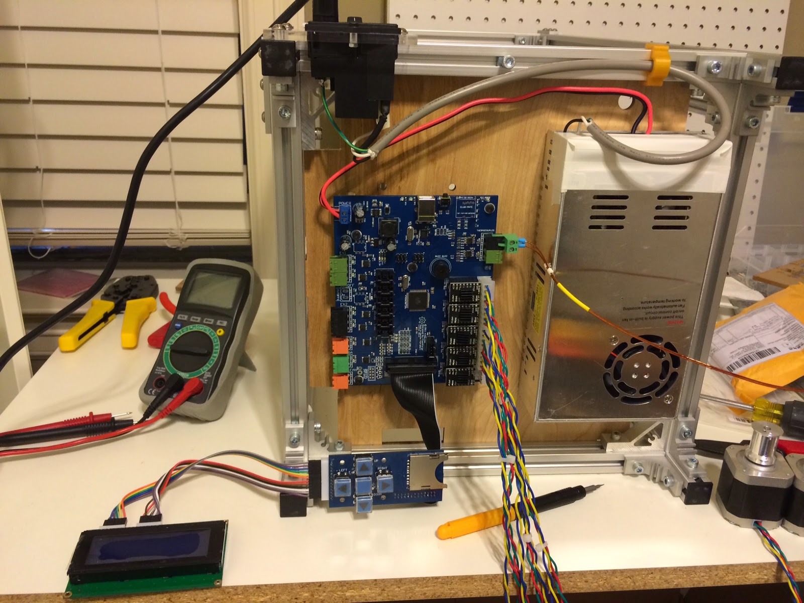
Hacking an endstop switch board to act as a HBP thermistor pull-up board:


Thermistor attachment:

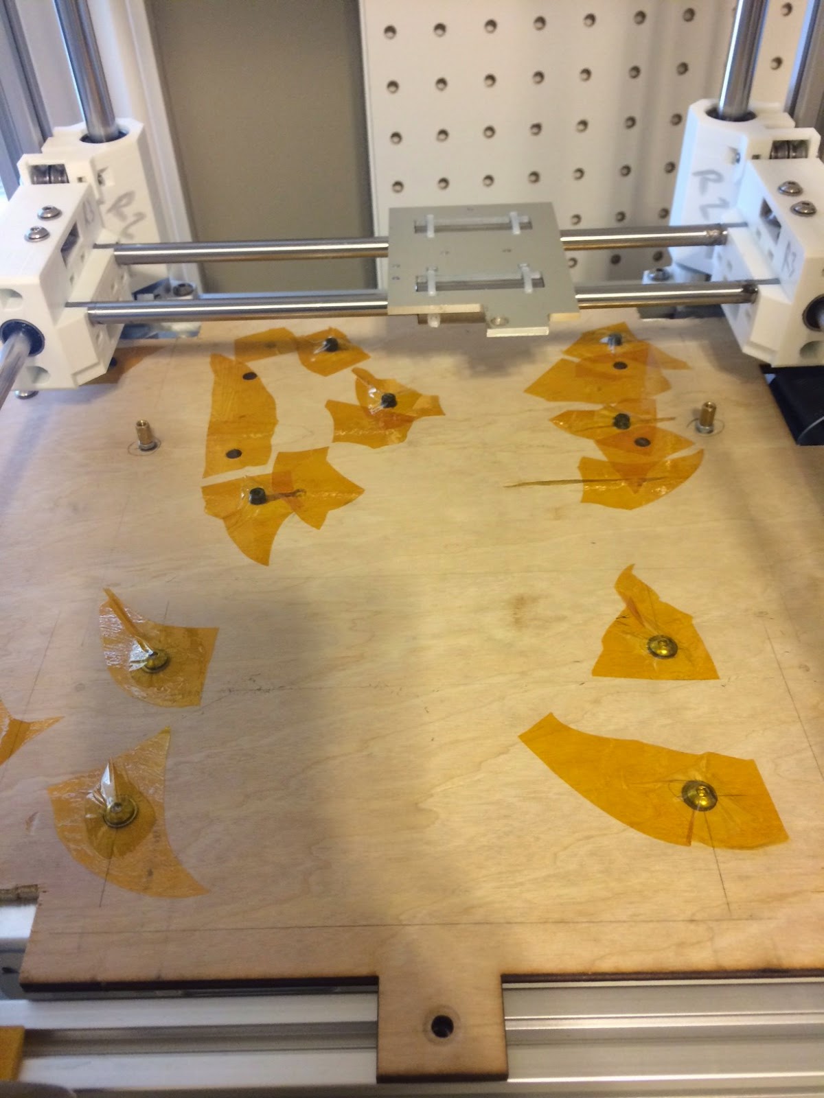
Prepping the wood floor plate. I'm a bit terrified of this MK3 aluminum heatbed shorting from a PCB heat trace to energize the entire plate, so I went ahead and covered all the electronics-mounting hardware with Kapton. A layer of aluminum tape went over that to reflect heat back at the heatbed.
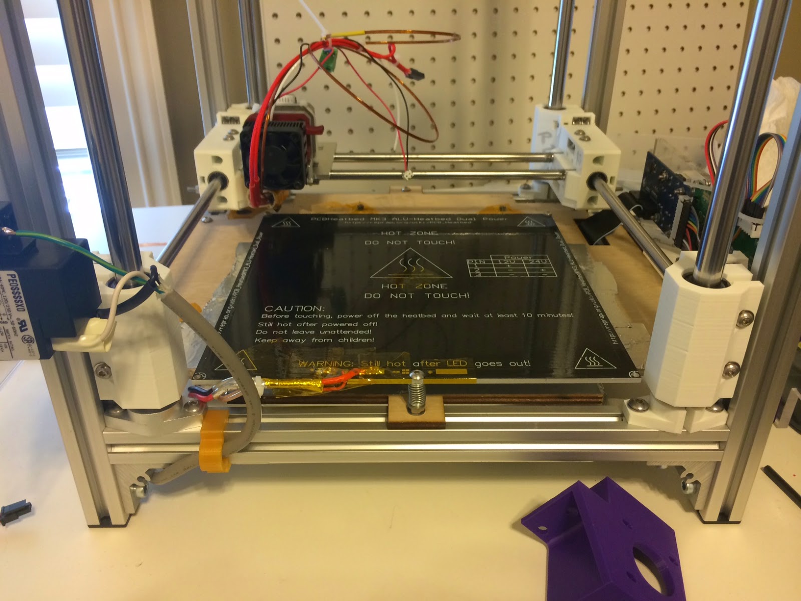
Stuff going together nicely:


Extruder and HBP both work like champs. I'm working on endstops now. (They are surprisingly tricky to fit in this design.) After that, I need to design the filament feed / wiring harness path to the extruder. I think it's going to jump off one of the Y-ends to reduce the length of the overhead U-loop. Haven't decided yet.
Gary Crowell
Draft Zmin endstop design. Uses standard MBI-style endstop switch. Bolts onto a Y-end with existing hardware. Has adjustable screw to set build plate gap (not rendered):
Putting together the MK3 aluminum heatbed. Aluminum heatbed = GIANT HEATSINK = horrible to solder on leads, dear lord this took me an hour and a 1200 watt heat-gun to preheat the whole plate hot enough to get solder to stick with a big-ass 120 watt soldering gun. I should'be used a torch.
Hacking an endstop switch board to act as a HBP thermistor pull-up board:
Thermistor attachment:
Prepping the wood floor plate. I'm a bit terrified of this MK3 aluminum heatbed shorting from a PCB heat trace to energize the entire plate, so I went ahead and covered all the electronics-mounting hardware with Kapton. A layer of aluminum tape when over that to reflect heat back at the heatbed.
Stuff going together nicely:
Extruder and HBP both work like champs. I'm working on endstops now. (They are surprisingly tricky to fit in this design.) After that, I need to design the filament feed / wiring harness path to the extruder. I think it's going to jump off one of the Y-ends to reduce the length of the overhead U-loop. Haven't decided yet.
I really want to rig up the steppers and spectra lines, but my final 12mm rod flanges got lost in the mail and won't arrive until Tuesday. $%#&ing UPS is useless sometimes. No point in running the Spectra line before I have the final rod brackets/alignment done.
--
You received this message because you are subscribed to the Google Groups "3DP Ideas" group.
To unsubscribe from this group and stop receiving emails from it, send an email to 3dp-ideas+...@googlegroups.com.
To post to this group, send email to 3dp-...@googlegroups.com.
To view this discussion on the web visit https://groups.google.com/d/msgid/3dp-ideas/63d16e95-29c8-4595-8b81-fa9d7887236d%40googlegroups.com.
Joseph Chiu
To view this discussion on the web visit https://groups.google.com/d/msgid/3dp-ideas/CAB%2B-abuMh-uv%2B-QzaHPUHHzZ-kj5RoSCf8AVz9XobpgS%3DZCXfw%40mail.gmail.com.
Ryan Carlyle
Christopher Matthes
Ryan Carlyle

Gary Crowell

scott.e...@gmail.com
Looks like this might be a nice application for an inexpensive and low-mass constant force (reel) spring.
Ryan Carlyle
scott.e...@gmail.com
Just a thought.
(Peel the Stanley label off and you go from prototype to production). ;)
Ryan Carlyle
Gary Crowell
Yeah, I reckon CF springs would be pretty good here. That's a thought.
Which reminds me, I need to do some torque/friction testing on these spectra pulleys. I need to figure out how many wraps are required for good holding force without going crazy on it. Also need to figure out whether the default Mightyboard Vref is going to drive these steppers with enough current or not.
Gary Crowell
Ryan Carlyle
On Saturday, August 30, 2014 4:23:44 PM UTC-5, Gary Crowell wrote:
Ryan Carlyle


I probably could have merged the blue and yellow parts into one piece, but this way made it easier to design for printability (wrt 45 degree rule and bridging). Plus maintenance is easier if the wiring run + cable chain can be pulled without a lot of extra stuff attached.

From a mechanical engineering standpoint, this is a TERRIBLE design. The fastening system is lopsided and the forces are all unbalanced. It's going to have a lot of unwanted flex in use. But for extremely light loading like this, convenience in attaching stuff together trumps good design practices.
Ryan Carlyle
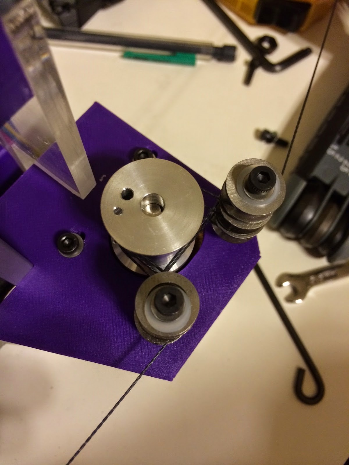
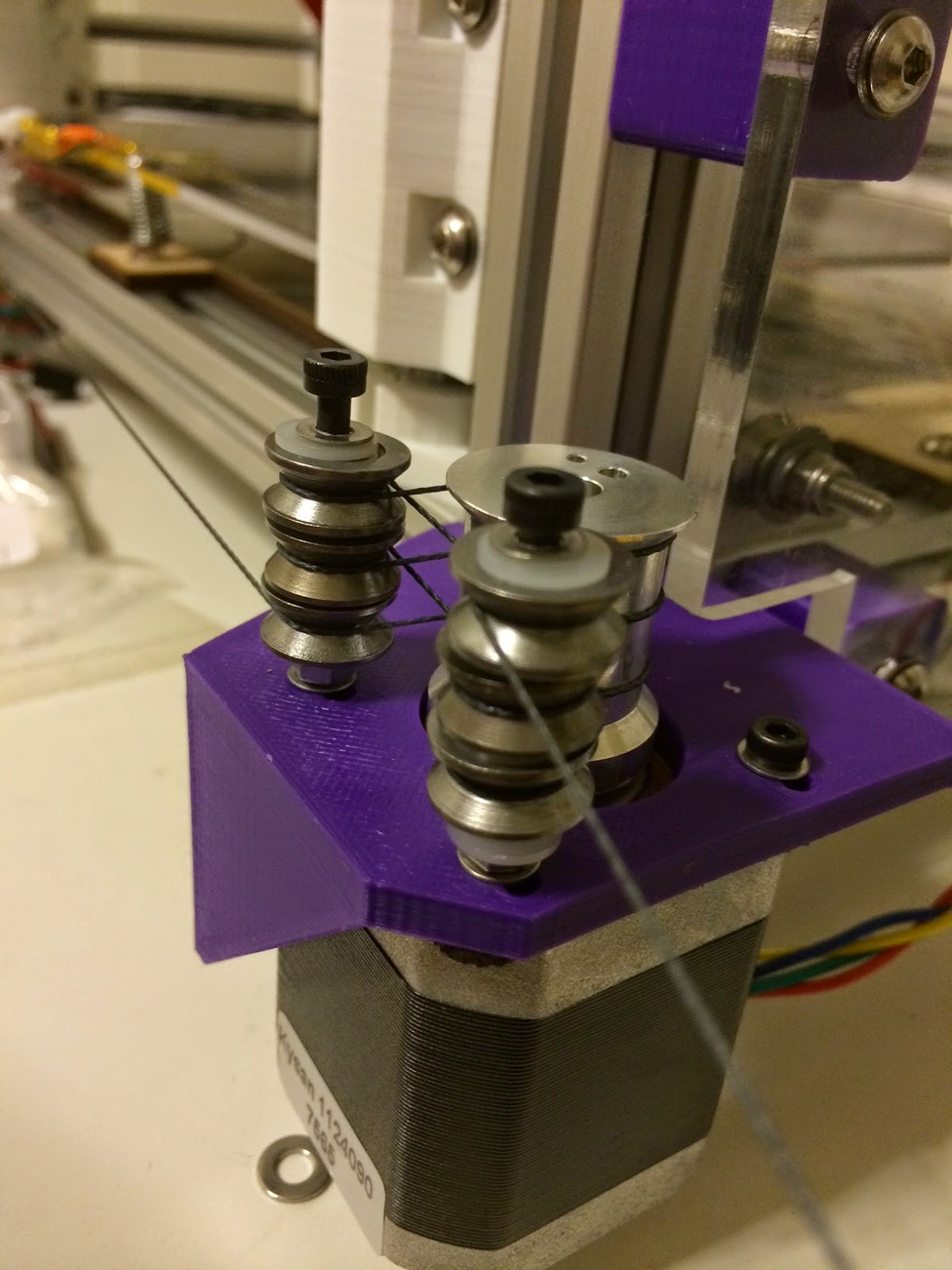
Another datapoint, it takes 5 wraps around the spool to generate enough capstan friction (with 325g back-tension) for the stepper to slip before the line/spool does. Which means the spectra-on-aluminum friction is pretty low. But I really need a good pull-scale or a set of weights or something to take full fiction/slip measurements. I might rig up something with a water jug so I can calculate the weight from water volume.
I'm a bit concerned about the spectra line walking up and down the spool and crossing itself during long Z moves where the spool is turning a ton due to the 3:1 reduction. I do have a workable solution for that but it will add another, oh, twenty? 624vv bearings to the system. Not my first preference.
Ryan Carlyle

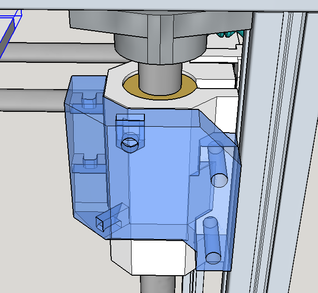
Installing brackets and steppers:


Ryan Carlyle


Ryan Carlyle

The endstop wiring will run through the cable chain along with all the carriage wires.

Chris P
Dan Newman
> Last update for the night. Got the X endstop sorted. (Note: on this build
> the gantry X and Y are flipped from the normal Replicator orientation. Long
> story.)
then standard builds will not support P-stop since standard builds
use X min for it.
Dan
Ryan Carlyle
Problem is fitting ~1600mm of wraps onto the spool for full travel including the 3:1 reduction pulleys on the tall Z axis. I think the spool is long enough to fit that much line if it packs efficiently, but the changing fleet angle may cause stacked wraps and that will throw off the steps/mm.
What's your bot use? Would you be willing to share a close-up pic of your CoreXY pulleys?
Ryan Carlyle
I decided this over the weekend, so the endstops would match the normal orientations. Yes, this is in conflict with my parts naming convention. But the LCD screen is rotated 90 degrees wrt the normal gantry to fit all the parts in, so it kind of works out. Bot cardinal directions are normal relative to the LCD.
Ryan Carlyle

Did it this way because I liked the way stuff fit together better. Easier access to the nozzle for leveling, easy build plate removal window, etc.
Chris P
Gary Crowell
--
You received this message because you are subscribed to the Google Groups "3DP Ideas" group.
To unsubscribe from this group and stop receiving emails from it, send an email to 3dp-ideas+...@googlegroups.com.
To post to this group, send email to 3dp-...@googlegroups.com.
To view this discussion on the web visit https://groups.google.com/d/msgid/3dp-ideas/85567e44-110c-4cb7-a174-a36aed07d5ae%40googlegroups.com.
Joseph Chiu
To view this discussion on the web visit https://groups.google.com/d/msgid/3dp-ideas/CAB%2B-abs0AGq6R0fUD5P8bcN-%2BeOwbq_OxVehq_1BKvFp7_np6Q%40mail.gmail.com.
scott.e...@gmail.com
Ryan Carlyle
On Thursday, September 4, 2014 2:58:34 PM UTC-5, Gary Crowell wrote:
Ok, last week I cut out the ABCD converter board, and I populated it over the weekend. I had a bit of a nightmare tracking down shorts, including one on the 5V bus that needed six or seven trace cuts to track down. In the end I just ran a knife tip along a short bit of trace and around a pad and the short went away. I never saw a thing, even under a very good microscope. There were a few other simple shorts, but I think I've got everything now. Checked continuity on all traces, and fixed a few misplaced components. I've applied power to it and there was no visible smoke; regulator is giving a good 5V. I'm hoping to be able to put a function generator and scope on it tonight.I still have to cut the botstep breakout boards but those are simple; can maybe do those tonight too. There will be a 10 pin ribbon cable from each breakout board to the ABCD board, though they really only carry step, dir, and ref; I have 10 pin cables laying around. Ryan, I have 4" and 9" cables. Which do you prefer, or will the 9" even be long enough? In a pinch, they could be pretty easily just jumped with wires point-to-point.Gary
On Thu, Sep 4, 2014 at 8:51 AM, Chris P <chris.pad...@gmail.com> wrote:
I use kossel style. Even with 5 wraps winch-style I was getting slip between the cable and the pulley. I was really surprised to see this but it was undeniably there. The other problem I had was keeping a winch-style wrap centered, because the walking forces are proportional to your cable tension and end up being extremely hard to overcome.
On Monday, September 1, 2014 7:22:05 PM UTC-4, Ryan Carlyle wrote:My plan was sailboat winch (simple capstan, ~5 wraps) with a centralization mechanism to limit wrap walking, but the kossel style may be better. That's the kind of pulleys I bought anyway.Problem is fitting ~1600mm of wraps onto the spool for full travel including the 3:1 reduction pulleys on the tall Z axis. I think the spool is long enough to fit that much line if it packs efficiently, but the changing fleet angle may cause stacked wraps and that will throw off the steps/mm.
What's your bot use? Would you be willing to share a close-up pic of your CoreXY pulleys?
--
You received this message because you are subscribed to the Google Groups "3DP Ideas" group.
To unsubscribe from this group and stop receiving emails from it, send an email to 3dp-ideas+unsubscribe@googlegroups.com.
To view this discussion on the web visit https://groups.google.com/d/msgid/3dp-ideas/85567e44-110c-4cb7-a174-a36aed07d5ae%40googlegroups.com.
Ryan Carlyle
Chris, I've got some tricks up my sleeve on the capstan walking problem. I regularly work with giant (>70,000 lbs) spooler units for 10,000 ft long subsea electrohydraulic umbilicals. And high-tension wireline pulling systems, and constant-tension motion-compensating systems, and 2.5 million lbs capacity oil rig derrick blocks. Managing motion of wires and hoses is a surprisingly large part of my job. What's hard for me about this is just miniaturizing these giant pieces of equipment to 3d printer scale using cheap parts.


(I would guess this is a ~100,000 lbs tension rated pulling unit, but that's a SWAG.)

Gary Crowell
To unsubscribe from this group and stop receiving emails from it, send an email to 3dp-ideas+...@googlegroups.com.
To view this discussion on the web visit https://groups.google.com/d/msgid/3dp-ideas/c9e6e54a-5d67-49f9-82c4-80936e3f8d5f%40googlegroups.com.
Ryan Carlyle
To view this discussion on the web visit https://groups.google.com/d/msgid/3dp-ideas/c9e6e54a-5d67-49f9-82c4-80936e3f8d5f%40googlegroups.com.
Christopher Matthes
Do you use these holes ? Does the green marked hole go vertical through the pulley ? Im asking because I will probably have the opportunity to make some custom pulleys out of steel next week. As there is a huge variety of them :

or:

or: http://www.thingiverse.com/thing:186988
I wanted to ask you for your preferences as I would love to help. What kind of pulley design do you prefer or would you change something? Do you want a 10mm diameter or 11, 12 ? Would you rather have a horizontal or vertical hole to stick the fishing line through it ?
Chris P
Ryan Carlyle


Once you get the filament looped through the spool, you string up one side of the carriage in the farthest-most position for that line. Then "wind up" the spool to pull the carriage to the diametrically-opposite position, and run the other side of the line on the opposite side of the gantry. It's kind of a pain.
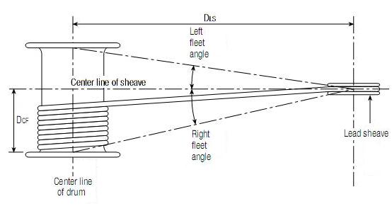
To make this work properly and not cross the wraps (which throws the steps/mm off and potentially tangles the line) you need to be careful about fleeting angles. The nearest idler to each side of the spool must be roughly level with that end of the spool, and sufficiently far away that as wraps accumulate, the fleet angle is never large enough to cause them to stack.
Ryan Carlyle
I need to rethink my carriage clips entirely. I'm thinking about something that can take up a lot of slack line, like a guitar tuning peg. Needs more engineering...
Christopher Matthes
Ryan Carlyle
For verifying the as-built against engineering drawings... I don't! The beauty of modeling the entire printer to scale is that all the parts come out pretty much exactly how they looked on the screen. At worst I do a fit-check, adjust a dimension or two, and reprint. The areas where I'm having trouble are the places that I didn't model rigorously.
Fishing line has some unique challenges, but belts would also be a pain with this design. It's just a lot of loops and routing. Belts would be easier, but not easy. I think what I need to do is rig up some sort of "spectra needle" to fish line through the pulleys easier. Maybe tape the end to a piece of nylon filament or something.
I guess if I were ordering custom pulleys to experiment with, I would do 12.5mm as a scientific guess. But the "correct" value depends on the size of spectra line used -- when it is under tension. My line is nominally "0.5" but the actual wrap pitch is about 0.3mm side-by-side and it's probably around 0.2mm "deep" on the spool. I haven't taken any rigorous measurements yet. But the effective diameter in mm should be [40/pi - thickness]. (Technically 2*thickness/2 but the 2s obviously cancel.)
Dan Newman
> I think what I need to do is rig up some sort of "spectra needle" to fish line through the pulleys easier.
> Maybe tape the end to a piece of nylon filament or something.
enough. E.g., BridgeAid Dental Floss Threaders.
Dan
Ryan Carlyle
Christopher Matthes
Ryan Carlyle


Ryan Carlyle

Ryan Carlyle

On Sunday, September 7, 2014 5:19:37 PM UTC-5, Ryan Carlyle wrote:
Sending to print.