Extrusion Width vs Nozzle Width

Ryan Carlyle

whosawhatsis
On Thursday, April 16, 2015 at 18:40, Ryan Carlyle wrote:
I'm in the camp that extrusion width should be the same as nozzle orifice width, unless you have a compelling reason to do otherwise, such as making thin-wall prints where wall thickness is close to the nozzle size and need to convince the slicer to fill the space. But LOTS of people think extrusion width should be larger than nozzle size. Why? What's the rationale?
--
You received this message because you are subscribed to the Google Groups "3DP Ideas" group.
To unsubscribe from this group and stop receiving emails from it, send an email to 3dp-ideas+...@googlegroups.com.
To post to this group, send email to 3dp-...@googlegroups.com.
To view this discussion on the web visit https://groups.google.com/d/msgid/3dp-ideas/b79269f1-c84f-4c57-9eac-29818018e4bd%40googlegroups.com.
For more options, visit https://groups.google.com/d/optout.

Petr Ptacek
whosawhatsis
To view this discussion on the web visit https://groups.google.com/d/msgid/3dp-ideas/b28d501e-86bd-40f7-91f1-4bf828b48ee9%40googlegroups.com.
Ryan Carlyle
Then, assuming it does come out roughly semi-circular, why is that a good thing? The more the cross-section bulges, the less likely you are to fill the corner voids when the adjacent strand goes down. More bulging = larger corner voids.
I can completely believe that wider extrusion widths are better for part strength, but to my mind, you'd be much better off using a larger nozzle to accomplish that, so you don't have as much side bulging or nozzle back-pressure.
Ryan Carlyle

Ryan Carlyle

Ryan Carlyle


Ryan Carlyle

Ryan Carlyle


whosawhatsis
--
You received this message because you are subscribed to the Google Groups "3DP Ideas" group.
To unsubscribe from this group and stop receiving emails from it, send an email to 3dp-ideas+...@googlegroups.com.
To post to this group, send email to 3dp-...@googlegroups.com.
To view this discussion on the web visit https://groups.google.com/d/msgid/3dp-ideas/848fb2d0-2f54-4d4a-bd5c-e59ee27f8bfe%40googlegroups.com.
Petr Ptacek
Ryan Carlyle
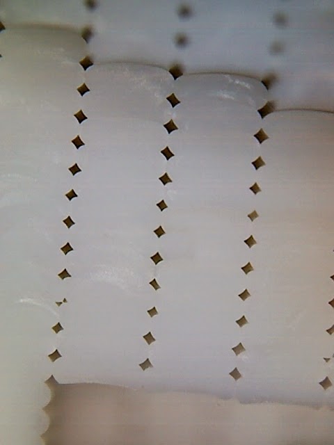
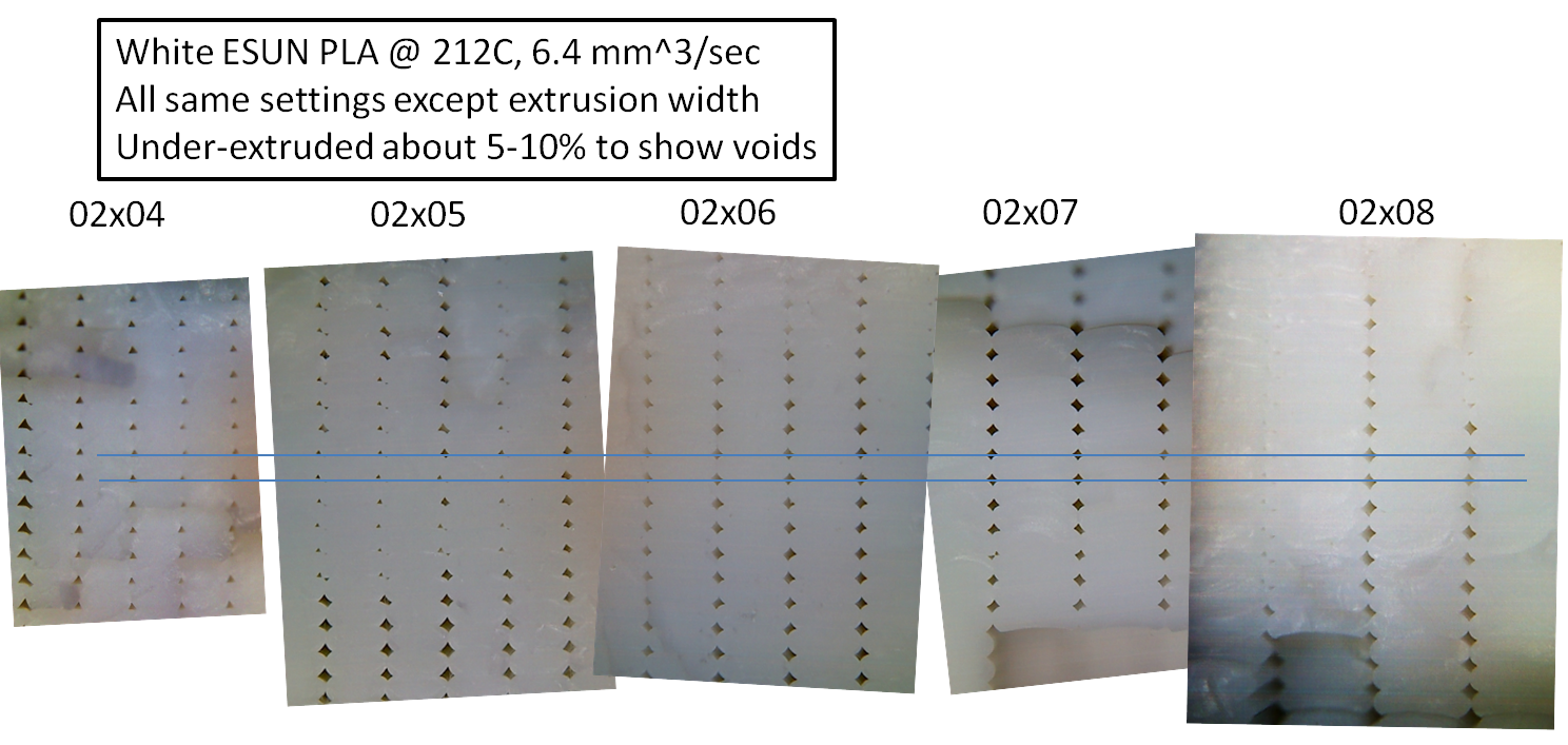
Just to clarify, by my formula, the extrusion width for a .2mm layer with a .4mm nozzle should be .6mm, not .8mm. The same should hold true as long as the extrusion width does not exceed the layer height plus the diameter of the flat on the end of the nozzle, but of course making the extrusion unnecessarily wide impares the ability to print small features in the X/Y plane.These images are showing pretty much what I expected. When your extrusion width is less than my formula demands, the plastic comes out as an inverted dome. The nozzle-facing side is pretty flat, but the other side is rounded so that it has only a small contact area with the previous layer. This is bad for layer adhesion, for optical properties when using translucent filaments, and the less predictable bulging of the sides is bad for dimensional accuracy of the surfaces.Seeing these images makes me wish even more that we had slicing algorithms smart enough to print perimeters on alternating half-layers so that they would pack hexagonally rather than rectangularly.


Ryan Carlyle

whosawhatsis
--
You received this message because you are subscribed to the Google Groups "3DP Ideas" group.
To unsubscribe from this group and stop receiving emails from it, send an email to 3dp-ideas+...@googlegroups.com.
To post to this group, send email to 3dp-...@googlegroups.com.
To view this discussion on the web visit https://groups.google.com/d/msgid/3dp-ideas/01578a3c-292b-4835-8394-3aa0ae8da1c0%40googlegroups.com.
Ryan Carlyle
Can't do any more tonight because my printer has been co-opted by an 8 hour Cookie Monster print. Family requests trump experiments :-)
Ryan Carlyle
Remember that you're intentionally under-extruding here. That overlap is caused by the adjacent line intruding into the current lines's area, which should not be happening when under extruding like this. Your shape will push the whole extrusion to the side then this happens, which will cause the line to be too far to the side, with the same gap under the rounded edge. With the .6 profile, the plastic will touch the layer below before it touches the side, and has a better chance of filling in under the adjacent line's curve, as well as above it.
whosawhatsis
--
You received this message because you are subscribed to the Google Groups "3DP Ideas" group.
To unsubscribe from this group and stop receiving emails from it, send an email to 3dp-ideas+...@googlegroups.com.
To post to this group, send email to 3dp-...@googlegroups.com.
To view this discussion on the web visit https://groups.google.com/d/msgid/3dp-ideas/5a87189f-eb40-4401-a21a-e354d9bc9fa5%40googlegroups.com.
Ryan Carlyle
On Friday, April 17, 2015 at 9:38:37 PM UTC-5, Whosa whatsis wrote:
That flow multiplier vs. back-pressure relationship is highly dependent on the drive gear you use. I've seen filament pulled from an Ultimaker (knurled drive) that clearly had about a 2.5x difference in the spacing of the tooth marks with only extrusion speed changed, but I've done similar tests with Deezmaker drive gears and was unable to get any measurable effect before the back-pressure got high enough to make the motor skip.On Friday, April 17, 2015 at 19:30, Ryan Carlyle wrote:
On Friday, April 17, 2015 at 7:44:56 PM UTC-5, Whosa whatsis wrote:--Remember that you're intentionally under-extruding here. That overlap is caused by the adjacent line intruding into the current lines's area, which should not be happening when under extruding like this. Your shape will push the whole extrusion to the side then this happens, which will cause the line to be too far to the side, with the same gap under the rounded edge. With the .6 profile, the plastic will touch the layer below before it touches the side, and has a better chance of filling in under the adjacent line's curve, as well as above it.Another data point... the 0.2x0.4 print is 7.93mm from a nominal 8.0mm. The 0.2x0.6 print is 5.91mm from a nominal 6.0mm. I also did another 0.2x0.4mm print with 4% more extrusion volume and it came out 8.02mm from a nominal 8.0mm. Visually, that last print is exactly what most people call perfect for volume calibration. You'd have to over-extrude to fit any more plastic into the corner voids.One thing I suspect is that you need to calibrate extrusion volume differently when you change extrusion width. Which makes sense, from a back-pressure standpoint. More extrusion width means you're pushing more rapidly-cooling plastic away from the nozzle, even though I'm normalizing feedrates for constant flow rate. So you should expect to have a bit more back-pressure and extrude a little less volume for the same nominal flow rate.
You received this message because you are subscribed to the Google Groups "3DP Ideas" group.
To unsubscribe from this group and stop receiving emails from it, send an email to 3dp-ideas+unsubscribe@googlegroups.com.
whosawhatsis
To unsubscribe from this group and stop receiving emails from it, send an email to 3dp-ideas+...@googlegroups.com.
To view this discussion on the web visit https://groups.google.com/d/msgid/3dp-ideas/05a5778d-723d-472a-b0a0-8f0643244b14%40googlegroups.com.
Ryan Carlyle

- Nominal test beam dimensions: 9.6m wide by 10mm tall (this is an integer multiple of strands for both prints)
- 0.2mm layer, 0.4mm width: 9.73 x 10.32 mm
- 0.2mm layer, 0.6mm width: 9.71 x 10.31 mm

- Maybe wider strands have more strand toughness, so they resist fracture propagation during brittle tension failure (perhaps due to a different degree of polymer alignment / crystallinity -- PLA is weird for this sort of thing)
- Maybe wider strands have less interlayer adhesion, so they delaminate easier


Chris P
Ryan Carlyle
whosawhatsis
On Saturday, April 18, 2015 at 16:17, Ryan Carlyle wrote:
Well, it seems possible. PLA is a really goofy material for stress/strain effects and crystallinity and such. (Look at the heat capacity curve from DSC experiments and you see multiple small crystallinity phase changes with history-dependent hysteresis.) It does form localized zones of aligned polymer strands that have crystal-like behavior when it's strained. So it's possible the added shear from higher extrusion width causes more alignment and that's somehow bad. Fewer free polymer ends available to diffusion-weld the layers together? But that's extremely speculative. Could be something exactly opposite... Maybe printing with width=nozzle keeps the polymer strands MORE aligned because they merely have to take a right turn out the nozzle, so you get more alignment between layers, and that's somehow good. Who knows.
--You received this message because you are subscribed to the Google Groups "3DP Ideas" group.To unsubscribe from this group and stop receiving emails from it, send an email to 3dp-ideas+...@googlegroups.com.To post to this group, send email to 3dp-...@googlegroups.com.
To view this discussion on the web visit https://groups.google.com/d/msgid/3dp-ideas/8a4b1a74-6b8f-4678-8aa6-c6182f41ea8e%40googlegroups.com.
whosawhatsis
--
You received this message because you are subscribed to the Google Groups "3DP Ideas" group.
To unsubscribe from this group and stop receiving emails from it, send an email to 3dp-ideas+...@googlegroups.com.
To post to this group, send email to 3dp-...@googlegroups.com.
To view this discussion on the web visit https://groups.google.com/d/msgid/3dp-ideas/a7b14548-d4a9-4c88-99e4-d23157126143%40googlegroups.com.
whosawhatsis
Ryan Carlyle
Keep in mind that plastic extruded into air will swell to a wider cross-sectional area than the nozzle bore (how much larger depends on a lot of factors, including extrusion speed), but if you're printing with nozzle width and a layer height less than pi/4 times that width (which is about the maximum layer height you would ever think of printing), you're stretching it to a smaller cross-sectional area than the nozzle. Logically, you would think there would be the least stress in the plastic if the cross-sectional area of the thread you lay down is equal to extruding at the same speed into air, which would make an extrusion wider than the nozzle better. This, of course, would be particularly true with amorphous materials and ones that are prone to warping, like ABS.
- 0.3mm high, 0.4mm wide
- 0.25mm high, 0.5mm wide
- 0.2mm high, 0.6mm wide
- 0.15mm high, 0.8mm wide
whosawhatsis
--
You received this message because you are subscribed to the Google Groups "3DP Ideas" group.
To unsubscribe from this group and stop receiving emails from it, send an email to 3dp-ideas+...@googlegroups.com.
To post to this group, send email to 3dp-...@googlegroups.com.
To view this discussion on the web visit https://groups.google.com/d/msgid/3dp-ideas/1e6a441e-ad63-4d77-94f4-aed82153966d%40googlegroups.com.
Ryan Carlyle
One super interesting aspect of high residual shear stress potentially being locked into extruded strands is that it wouldn't just increase or decrease ABS warping... it would skew the stresses. If we assume the extruder always does perimeters in the same direction, any locked-in nozzle shear stress will be aligned with / amplify thermal contraction stress at the first half of each straight line segment, and counteracting thermal contraction stress at the second half of each straight line segment.

whosawhatsis
--
You received this message because you are subscribed to the Google Groups "3DP Ideas" group.
To unsubscribe from this group and stop receiving emails from it, send an email to 3dp-ideas+...@googlegroups.com.
To post to this group, send email to 3dp-...@googlegroups.com.
To view this discussion on the web visit https://groups.google.com/d/msgid/3dp-ideas/97e27273-ff97-4fdc-909c-9b6d0d28674d%40googlegroups.com.
Ryan Carlyle
On Saturday, April 18, 2015 at 8:23:08 PM UTC-5, Whosa whatsis wrote:
That is interesting, and PLA may or may not crystalize in a way that increases strength when you draw it out, but it seems unlikely that ABS would, and it should be stronger and less prone to warping (as well as things like constricting holes) when the polymers are stretched less, right?Even if PLA does crystalize when you draw it out, the higher flexibility of a larger extrusion area is probably preferable for certain applications.
Ryan Carlyle
whosawhatsis
--
You received this message because you are subscribed to the Google Groups "3DP Ideas" group.
To unsubscribe from this group and stop receiving emails from it, send an email to 3dp-ideas+...@googlegroups.com.
To post to this group, send email to 3dp-...@googlegroups.com.
To view this discussion on the web visit https://groups.google.com/d/msgid/3dp-ideas/323d96ce-6ef9-4163-a062-597a1bb11113%40googlegroups.com.
Ryan Carlyle


Ryan Carlyle
Ryan Carlyle


Ryan Carlyle
Whosa whatsis
Ryan Carlyle
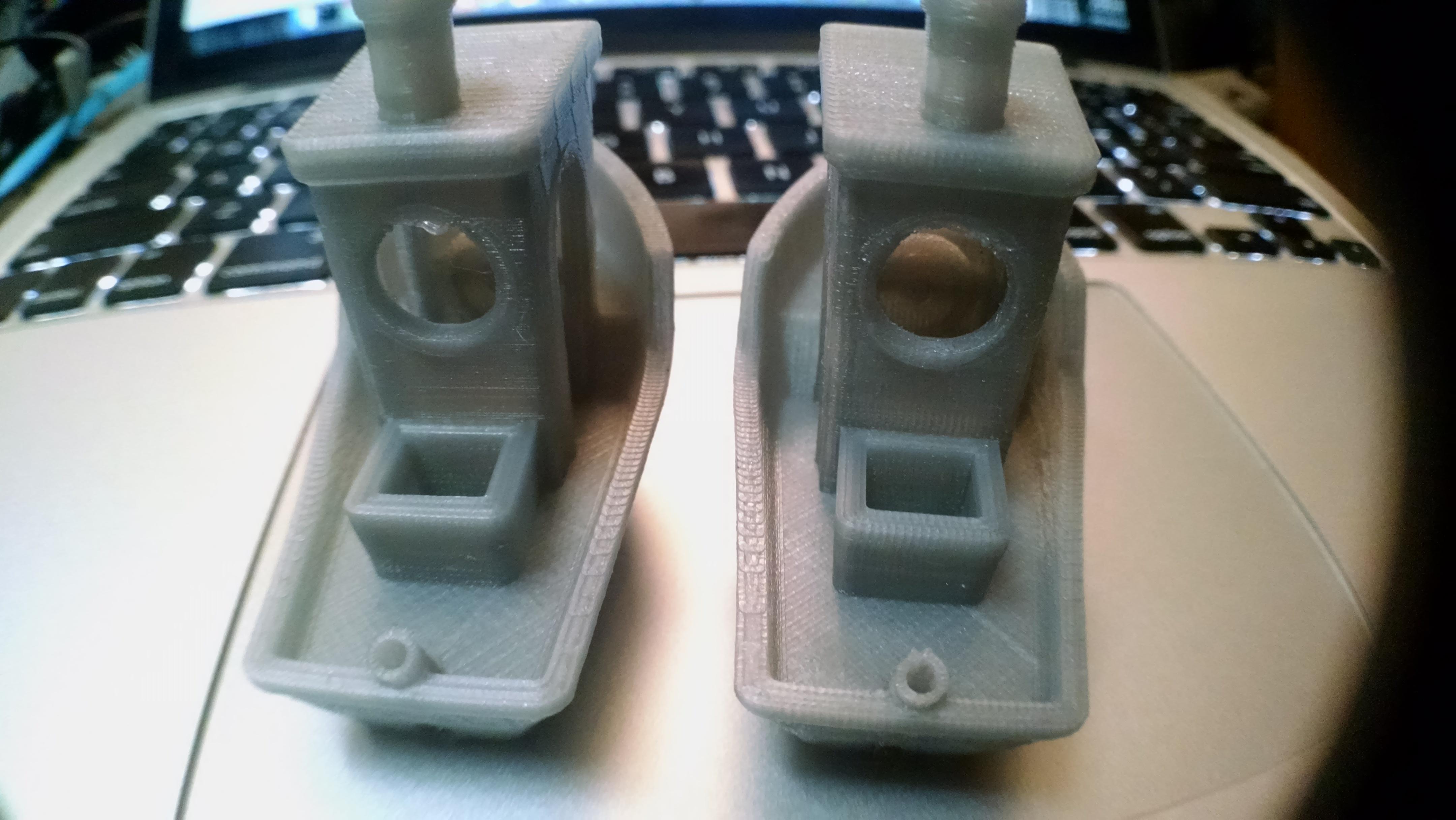
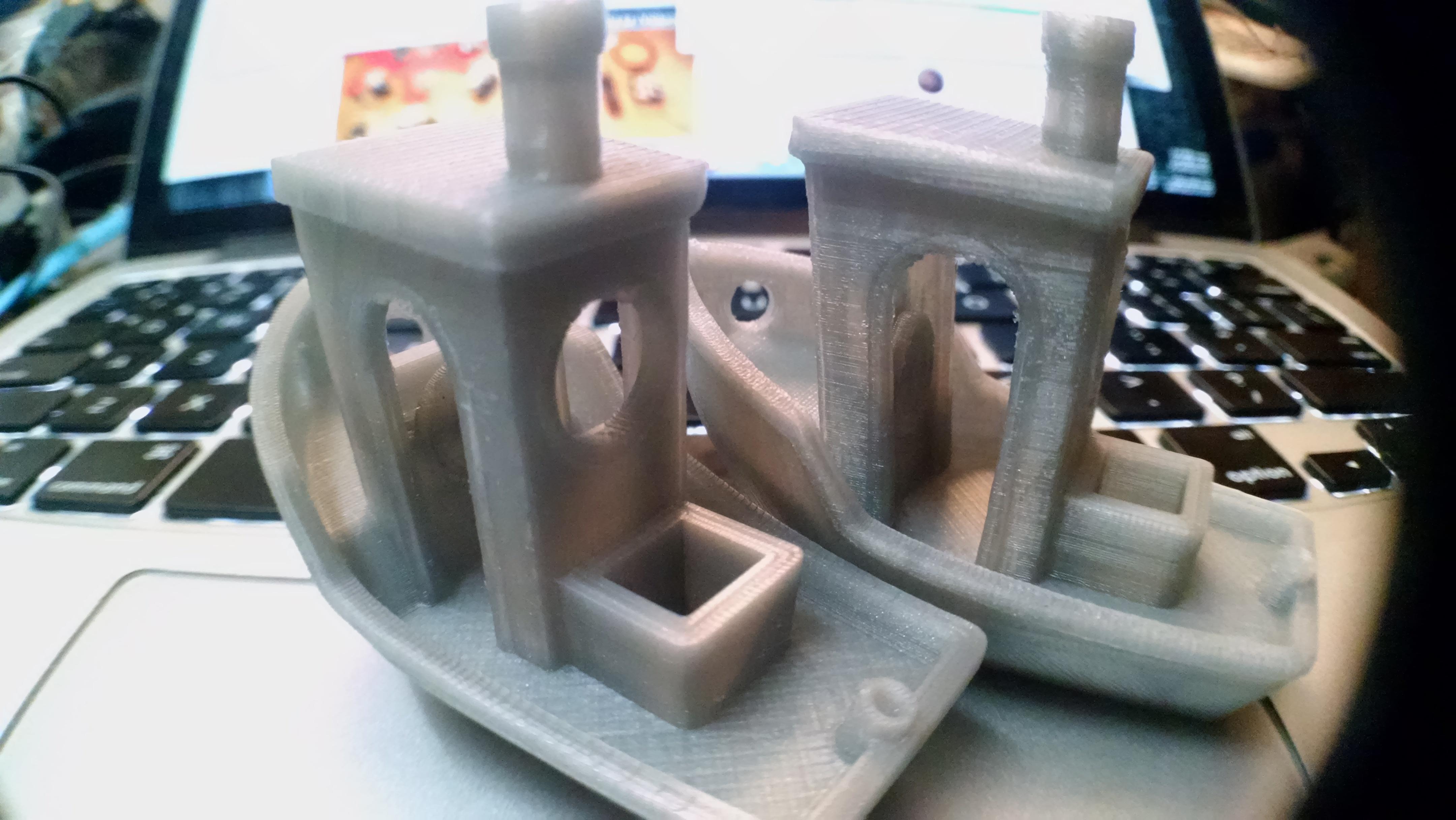
Which slicer is this? It looks to me like your .6mm width print is actually over-extruded a bit, judging by the look of the floors by the base. That could be causing some of the color consistency differences. Over-extrusion = smaller gaps.

Joseph Chiu
Keep in mind that for some colorants used in filament, the temp and dwell time in the hot end may affect the color of the output it as it is being extruded.
That's an interesting distinction that I hadn't thought of. Optical properties of translucent filaments do seem like they should be better with wider extrusion due to the more oval cross-section. Although there was no real difference in total quantity or consistency of air pockets in my test pieces. The shape distribution was certainly different.
Which slicer is this? It looks to me like your .6mm width print is actually over-extruded a bit, judging by the look of the floors by the base. That could be causing some of the color consistency differences. Over-extrusion = smaller gaps.
--
You received this message because you are subscribed to the Google Groups "3DP Ideas" group.
To unsubscribe from this group and stop receiving emails from it, send an email to 3dp-ideas+...@googlegroups.com.
To post to this group, send email to 3dp-...@googlegroups.com.
To view this discussion on the web visit https://groups.google.com/d/msgid/3dp-ideas/32f13fe9-bd0b-4eed-837a-e82dfc0c5e72%40googlegroups.com.
whosawhatsis
On Thursday, April 30, 2015 at 10:31, Ryan Carlyle wrote:
That's an interesting distinction that I hadn't thought of. Optical properties of translucent filaments do seem like they should be better with wider extrusion due to the more oval cross-section. Although there was no real difference in total quantity or consistency of air pockets in my test pieces. The shape distribution was certainly different.Which slicer is this? It looks to me like your .6mm width print is actually over-extruded a bit, judging by the look of the floors by the base. That could be causing some of the color consistency differences. Over-extrusion = smaller gaps.
--You received this message because you are subscribed to the Google Groups "3DP Ideas" group.To unsubscribe from this group and stop receiving emails from it, send an email to 3dp-ideas+...@googlegroups.com.To post to this group, send email to 3dp-...@googlegroups.com.
To view this discussion on the web visit https://groups.google.com/d/msgid/3dp-ideas/32f13fe9-bd0b-4eed-837a-e82dfc0c5e72%40googlegroups.com.

tray
Ryan Carlyle
whosawhatsis
To view this discussion on the web visit https://groups.google.com/d/msgid/3dp-ideas/6919b638-798a-40f9-81af-e68e17e88415%40googlegroups.com.
Ryan Carlyle

To unsubscribe from this group and stop receiving emails from it, send an email to 3dp-ideas+unsubscribe@googlegroups.com.
Chris P
Ryan Carlyle
- Disentangling slicer-specific behaviors and printer calibration quirks from real results
- Applying strains at rates that don't misrepresent material strengths
- Controlling and documenting non-obvious inputs like print speed and room temperature and filament pigment load
whosawhatsis
To view this discussion on the web visit https://groups.google.com/d/msgid/3dp-ideas/f0897c4f-587f-46a4-a3f5-fb44771cb48a%40googlegroups.com.
Ryan Carlyle
whosawhatsis
On Friday, November 6, 2015 at 07:00, Ryan Carlyle wrote:
Agreed, there are some test protocol issues. We could use a standard for this kind of testing.
--You received this message because you are subscribed to the Google Groups "3DP Ideas" group.To unsubscribe from this group and stop receiving emails from it, send an email to 3dp-ideas+...@googlegroups.com.To post to this group, send email to 3dp-...@googlegroups.com.
To view this discussion on the web visit https://groups.google.com/d/msgid/3dp-ideas/19e59407-116f-4220-9645-0da629f1018d%40googlegroups.com.