Differential Belt Z Stage
592 views
Skip to first unread message

Ryan Carlyle
Jan 15, 2015, 5:18:26 PM1/15/15
to 3dp-...@googlegroups.com
Anybody ever see a differential pulley before? I've been trying to figure out where to put one in a 3d printer, because they're cool. (No real reason aside from that.) I think I came up with a decent option for a Z stage lift mechanism.
If you've done much thinking about belt-driven or spectra-driven Z stages, you know that the issue is always the steps/mm being too low for proper layer height resolution. So almost everybody uses lead screws for the Z axis. The only real alternative is setting up a pulley reduction system to get some mechanical advantage after the main stepper drive.
Given standard Replicator type dimensions and electronics, you want to target 400 steps per mm for the Z stage. Or, more relevant for lead screws, 8mm travel per motor rev. This is a "sweet spot" compromise between speed and print quality. In order to achieve 8mm per rev with a GT2 belt, you would need a four-tooth pulley, which is clearly impossible. BUT, you could set up a differential pulley arrangement that achieves 4 teeth per rev using a 16t pulley and 20t pulley on the same shaft.
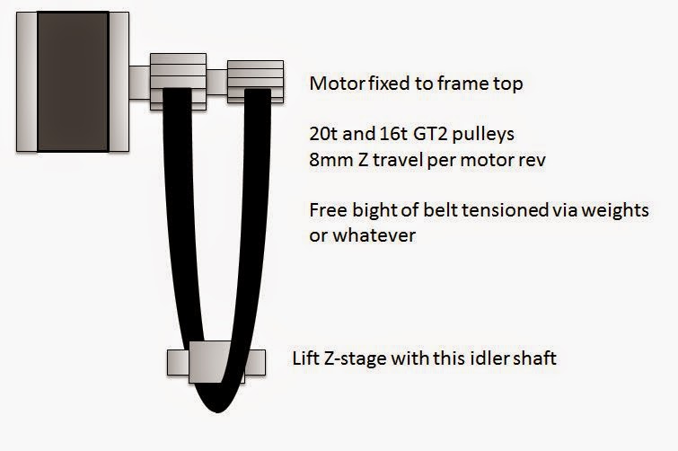
Of course, this form factor sucks. The free loop of belt on the other side of the drive pulleys (not shown) needs to be kept tight with weights/springs to keep the belts from jumping teeth. And it's still a single-point lift, like cantilevered lead screw Z stages, which sucks. So here's rev 2:
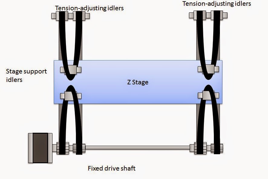
Now we have a two-point lift driven off one motor with rigid couplings, which ain't bad. (Not as good as three-point, but way better than cantilevering.) It's 8mm per motor rev, which is a drop-fit replacement for our favorite tr8x8 lead screws. It eliminates the expensive screws and a major lubrication point on the bot. And since the belts are tension only, there's no risk of screw wobble or backlash.
I see two big design issues though:
- Z stage length is limited to the availability of endless loop belts, eg 2.2 meter GT2 belt gives a max stage length of ~500mm. Not all of that will be usable. That's still a pretty dang big Z stage though.
- Routing the belt through the idler arrangement will require twisting it a quarter turn per pass. I'm not sure how much this really matters, but it's a consideration.

Dan Newman
Jan 15, 2015, 6:40:11 PM1/15/15
to 3dp-...@googlegroups.com
On 15/01/2015 2:18 PM, Ryan Carlyle wrote:
> Anybody ever see a differential pulley
> <http://en.wikipedia.org/wiki/Differential_pulley> before?
> Anybody ever see a differential pulley
I've seen and used them; just didn't know them by that name. My father
and his buddies like restoring old cars. I've used them lifting engines
and trannies.
Dan
Ryan Carlyle
May 30, 2016, 7:14:12 PM5/30/16
to 3dp-...@googlegroups.com
Turns out, a good way to implement this concept is patented. http://www.google.com/patents/US8516913

Zatsit
May 31, 2016, 5:23:14 AM5/31/16
to 3DP Ideas
Not that good in my opinion:
When the carriage approaches an end, misalignment of the belt becomes prohibitive. It is better that this misalignment occurs on a branch of the belt circuit, of fixed length.
Using a Dyneema braid in place of a timing belt, both driving pulleys can be placed almost in the same plane, thus minimizing misalignments. The driving pulleys can be of large diameter, since only their difference are important. So, the slipping possibilities under stress are minimized.
I did such a system, with incomplete success : Connecting the two ends of the braid (per knot or splice) causes an unavoidable extra thickness, which is the source of an error when this additional thickness passes over a pulley. This negative effect can be made acceptable if the change in thickness is very small relative to the radius of the pulley.
In conclusion, the differential pulley systems with cables could be an excellent solution, if we can integrate them into architectures with pulleys of very large radius.
Ryan Carlyle
May 31, 2016, 2:54:18 PM5/31/16
to 3DP Ideas
I still want a way to splice synchromesh cable so it can be used as an endless loop. Bead belts might also work.

Whosawhatsis
Jun 1, 2016, 1:13:04 AM6/1/16
to Ryan Carlyle, 3DP Ideas
What about posi-drive? https://www.sdp-si.com/D795/HTML/79501057.html
--
You received this message because you are subscribed to the Google Groups "3DP Ideas" group.
To unsubscribe from this group and stop receiving emails from it, send an email to 3dp-ideas+...@googlegroups.com.
To post to this group, send email to 3dp-...@googlegroups.com.
To view this discussion on the web visit https://groups.google.com/d/msgid/3dp-ideas/802f13b2-2621-49da-9876-218cc4d42947%40googlegroups.com.
For more options, visit https://groups.google.com/d/optout.
Ryan Carlyle
Jun 1, 2016, 11:53:19 AM6/1/16
to 3DP Ideas
Ooh, didn't know posi-drive was so easy to splice.
I wonder if posi-drive has the same speed variation/vibration while meshing that chain/sprocket drives do.

Chris P
Jun 7, 2016, 10:20:54 PM6/7/16
to 3DP Ideas
In both of them you have a circular chain element paying on and off a toothed sprocket, so my bet is yes. It might even be worse than a bike chain, since the rollers on a bike chain can spin as they mesh and unmesh from the sprocket whereas the pins on this stuff are not free to spin.
Ryan Carlyle
Jun 7, 2016, 11:55:41 PM6/7/16
to 3DP Ideas
From the limited drawings I can find, it looks like for the single-strand version (which is the one you can use for 3d routing and twists) the core actually runs on a smooth circular channel between the teeth. Which would imply it has hella backlash. But the two-strand version seems to run on a sprocket just like a chain.
Kind of wondering if ball chains ought to make a comeback! I know some people played around with those back in the day.
Ryan Carlyle
Nov 12, 2016, 11:11:14 PM11/12/16
to 3DP Ideas
It comes to mind that this simple differential winch drive could make a pretty good spectra line Z stage...

Obviously, all the usual spectra winch issues with wrap walking and fleeting angle and such apply. It's attractively simple though. Could be a good RepRap Z stage design with printed spools since the net motion stage travel per rev is only pi*(D1-D2)/2 and thus any print flaws in the parent spool will produce smaller flaws in the child spool. It would be best-suited to printers with a single Z actuator (like a cantilevered Z bed) and a relatively small amount of Z travel.

dan...@puptv.com
Nov 13, 2016, 1:09:51 AM11/13/16
to 3DP Ideas
It seems like it is much better in situations where you need either a great deal of efficient mechanical advantage or incredible accuracy/resolution. From what I can tell, it is one of the most efficient high mechanical advantage mechanisms. A harmonic gear with roller bearings on the inside axle can be very efficient as well.
Daniel - http://www.TriDPrinting.com/
Daniel - http://www.TriDPrinting.com/
Ryan Carlyle
Nov 13, 2016, 1:28:39 PM11/13/16
to 3DP Ideas
The basic mechanism can have a mechanical advantage anywhere from 2:1 to infinity, on top of the travel per rev of the larger pulley attached to the motor. The main constraint is that the bigger the mechanical advantage, the more line wraps you have to manage.
If we consider what we do with Z screws, something from 1mm to 10mm travel per rev is a good target. That means the difference in spool circumferences needs to be 2mm to 20mm, which means diameter differences from 2/pi=0.637mm to 20/pi=6.37mm. I could see something like a 20mm diameter spool and a 26.37mm diameter spool. The bigger spool would have 82.8mm circumference or line length per motor rev. The net motion is 10mm per motor rev. So for a 100mm travel Z stage, you would need 828mm of line travel or 10 wraps, which is pretty reasonable for a spectra line.

Mark Napier
Nov 16, 2016, 10:46:00 AM11/16/16
to 3DP Ideas
Why not just a planetary gearbox on the stepper?
Ryan Carlyle
Nov 16, 2016, 11:35:02 AM11/16/16
to 3DP Ideas
Cost, RepRap self-replication capability, wider range of "gear ratios," looks cooler :-)

Marc Lee
Nov 16, 2016, 9:22:57 PM11/16/16
to 3DP Ideas
How do you mitigate the Z-error due to the Z-belts stretching: (a) as the supporting belt length varies (same load on more belt length => more stretch error); and (b) as the bed weight varies due to part weight increasing?
Ryan Carlyle
Nov 16, 2016, 9:41:53 PM11/16/16
to 3DP Ideas
Braided spectra fishing line and GT2/GT3 belts are pretty dang low elasticity. Everything in this thread is only really suitable for fairly short Z stages because of the length of belt/line required to get the mechanical advantage. Using a 2:1 pulley arrangement further spreads the weight over two lines to cut the stretch in half. And the change in stretch will occur very gradually over many layers, so it's arguably something you can calibrate out with steps/mm adjustment. In my opinion, stretch is simply going to be a non-issue unless you're trying to build a huge Z stage like for a 1m cube printer.
I forget which thread it was, but we had a good discussion about Z belt stretch variation here a while back.
Marc Lee
Nov 16, 2016, 10:01:59 PM11/16/16
to 3DP Ideas
Yes, as I remember, our previous discussion came down to the assumption that belts/line elasticity is less at 3DP working tensions than manufacturer specs which perhaps applied to much smaller tensions. I haven't yet quantified how much elasticity decreases at 3DP tensions. Have you?
With XY, elasticity promotes ringing. With Z, (especially longer Z and heavier beds) elasticity promotes resonance and potentially positional errors varying with height. We just need to quantify it for each design. Of course, some elasticity is good otherwise the printer would jerk itself to bits (and trees would snap in the wind!)
Ryan Carlyle
Nov 17, 2016, 10:30:22 AM11/17/16
to 3DP Ideas
Yeah, I've never seen a stretch-vs-tension curve to see how much it taken out by preload. I know the elasticity decreases with preload but we need more info to calculate stretch. It shouldn't be too hard to measure and plot belt stretch... Just need a known free length (eg 2 meters) hanging vertically, then hang different masses and measure the stretch with a dial indicator or something. Would take a small amount of engineering to rig it up properly, but it ought to be adequately accurate.
Reply all
Reply to author
Forward
0 new messages