Threadless Ball Screw-der
2,310 views
Skip to first unread message

Ryan Carlyle
Jul 18, 2014, 10:12:11 PM7/18/14
to 3dp-...@googlegroups.com
I'm probably not the first person to think of this, but it's an interesting concept that occurred to me a while back. Consider a threadless ball screw like this:

The radial bearings have a high-friction interference fit with the linear shaft, but contact with a helical pitch, which means they spin on a smooth shaft just like a nut spins on a threaded shaft. So you can spin the shaft and hold the bearing carrier nut to create a linear actuator. Or you can spin the carrier nut and hold the shaft. Same effect.
What I want to do is make a version sized to grab onto filament instead of a linear shaft. (Maybe with flanged bearings that have a little sharper edges and more axial capacity than the usual radial bearings.) Then spin the carrier nut to push the filament.
It would probably require two counter-rotating carrier nuts to keep the filament from twisting. And you'd need some sort of tensioning mechanism to allow for variable filament diameter. Here's some sketches:

But why? Regular extruders work fine. Threadless ball screws actually do not have very good repeatability because they're very sensitive to bearing angle slop, and need to be driven in a servo style closed-loop mechanism to be precise. This is why they're not used for printer Z stages.
Really, it just makes belt-multiplexed extruder drives like CoreXE and CoreXYAB (https://groups.google.com/forum/#!topic/3dp-ideas/Xv-tC_bf708) mechanically simpler. The ability to spin a vertical-axis drive mechanism allows a belt-multiplex extruder drive to keep everything coplanar and avoid right-angle gears on the carriage. You'd pretty much just stick the carrier nut inside a large GT2 pulley, wrap a drive belt around it, and mount it on a carriage.

Joseph Chiu
Jul 18, 2014, 10:39:18 PM7/18/14
to Ryan Carlyle, 3dp-...@googlegroups.com
Not to mention that the filament roundness is far from ideal in most cases...
--
You received this message because you are subscribed to the Google Groups "3DP Ideas" group.
To unsubscribe from this group and stop receiving emails from it, send an email to 3dp-ideas+...@googlegroups.com.
To post to this group, send email to 3dp-...@googlegroups.com.
To view this discussion on the web visit https://groups.google.com/d/msgid/3dp-ideas/3cd4ee9b-02a7-4b5a-bde1-790e27d3c79b%40googlegroups.com.
For more options, visit https://groups.google.com/d/optout.
Ryan Carlyle
Jul 18, 2014, 10:47:37 PM7/18/14
to 3dp-...@googlegroups.com, temp...@gmail.com, joe...@joechiu.com
Yeah, that could be an issue. Ovality would, naturally, require travel in whatever conformable preload system is used. Could add some vibration modes during rapid extrusion/retraction.
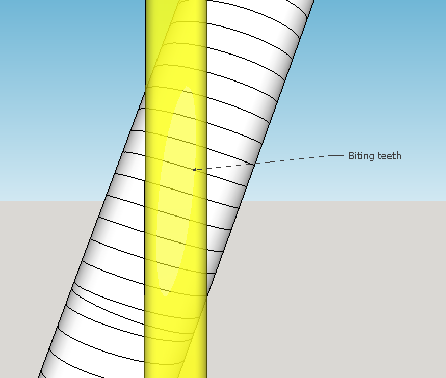
I expect the bearings to cut into the filament a fair bit. Bite depth may compensate for some diameter differences, but of course we all know what happens when there's no spring-tensioning mechanism in an extruder...

Vernon Barry
Jul 19, 2014, 2:42:08 PM7/19/14
to 3dp-...@googlegroups.com, temp...@gmail.com, joe...@joechiu.com
My concern is the limited amount of bite into the filament. This seems to depend on high pressure and limited contact area. The instant you angle the bearings for more bite- now that is worst case load on a single row bearing.
By all means, I guess try it but also, likely to work better on 3mm filament VS 1.75..
On Friday, July 18, 2014 10:47:37 PM UTC-4, Ryan Carlyle wrote:
Joseph Chiu
Jul 19, 2014, 3:06:23 PM7/19/14
to Vernon Barry, 3dp-...@googlegroups.com, Ryan Carlyle
Ryan, have you ever seen the BfB filament drive? It seems relevant to this...
--
You received this message because you are subscribed to the Google Groups "3DP Ideas" group.
To unsubscribe from this group and stop receiving emails from it, send an email to 3dp-ideas+...@googlegroups.com.
To post to this group, send email to 3dp-...@googlegroups.com.
To view this discussion on the web visit https://groups.google.com/d/msgid/3dp-ideas/40872cdd-74cc-41fc-893d-18b8d6ee017b%40googlegroups.com.
Ryan Carlyle
Jul 19, 2014, 4:46:08 PM7/19/14
to 3dp-...@googlegroups.com
I'm googling but can't find a diagram. Just finding vague blog posts. Is the BfB extruder a worm screw drive? Stratasys has made a lot of those over the years.
I'm thinking 3mm ABS is probably the only filament this will credibly work with. You need to get some bite and you need some reasonable thickness to get three bearings in place adequately. Basically HAVE to use tilted flanged bearings to get everything to fit close enough, and get a decently sharp edge, and survive the axial load.
Ryan Carlyle
Dec 25, 2014, 11:16:34 PM12/25/14
to 3dp-...@googlegroups.com
Ok, I found some good pics of the BfB extruder and it got me thinking.
First, the BFB extruder IS a screw drive, but the screw is mounted at a shallow angle to the filament path instead of being parallel like a typical worm screw / auger type pusher. This does two things:
1) Lets the filament run straight through the extruder without worrying about the filament feed/output path clashing with drive screw gears/bearings like it would clash if the screw were parallel to the filament.
2) Makes the screw threads cut the filament (close to) perpendicular to the filament length, just like a typical hobbed bolt / drive gear teeth bite. That reduces twisting load placed on the filament due to screw rotation.
If the screw diameter and pitch are chosen well, this arrangement can give significantly more teeth engaged on the filament at a time than any normal diameter drive gear. So that's a really cool design concept.
The problem is, the screw still has to rotate to drive the filament. That means a large amount of drag force where the threads slide across the filament. Much of the drive force will be taken up by rotating drag. This drag will be roughly proportional with bite force on the idler bearings, and with pushing force. Having too much drag will spin the filament and cause the extruder to stall or push an inconsistent volume. Plus, any flaws on the threads will abrade the heck out of the filament and generate plastic dust, which apparently was a common conplaint about the design. That's all bad.
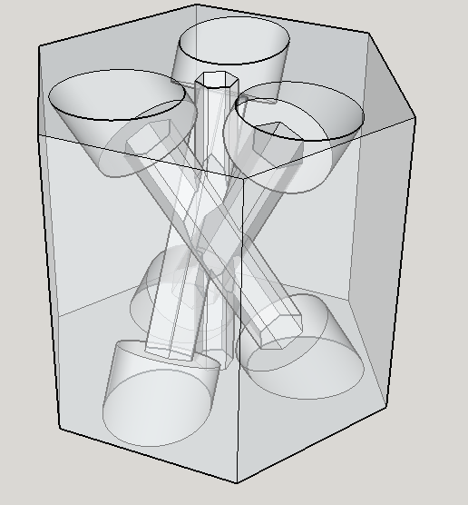
My thought is to combine the "threadless ballscrewder" concept (of rotating flanged bearings around the filament) with the BfB extruder concept (of spinning an angled screw to push the filament).
Three screws will be angled around the filament, mounted on bearings. And then the bearing cage will spin around the filament just like the threadless ball screw concept. Basically, the superior tooth shape/grip and smaller diameter of the screws is used to improve on the flanged bearings typically used.
I feel like this is a reasonably workable design, at least from a filament-biting standpoint. Obviously, there are still engineering challenges around the mechanisms to tension the screws against the filament and how to spin the bearing cage. But that's all workable.
First, the BFB extruder IS a screw drive, but the screw is mounted at a shallow angle to the filament path instead of being parallel like a typical worm screw / auger type pusher. This does two things:
1) Lets the filament run straight through the extruder without worrying about the filament feed/output path clashing with drive screw gears/bearings like it would clash if the screw were parallel to the filament.
2) Makes the screw threads cut the filament (close to) perpendicular to the filament length, just like a typical hobbed bolt / drive gear teeth bite. That reduces twisting load placed on the filament due to screw rotation.
If the screw diameter and pitch are chosen well, this arrangement can give significantly more teeth engaged on the filament at a time than any normal diameter drive gear. So that's a really cool design concept.
The problem is, the screw still has to rotate to drive the filament. That means a large amount of drag force where the threads slide across the filament. Much of the drive force will be taken up by rotating drag. This drag will be roughly proportional with bite force on the idler bearings, and with pushing force. Having too much drag will spin the filament and cause the extruder to stall or push an inconsistent volume. Plus, any flaws on the threads will abrade the heck out of the filament and generate plastic dust, which apparently was a common conplaint about the design. That's all bad.
My thought is to combine the "threadless ballscrewder" concept (of rotating flanged bearings around the filament) with the BfB extruder concept (of spinning an angled screw to push the filament).
Three screws will be angled around the filament, mounted on bearings. And then the bearing cage will spin around the filament just like the threadless ball screw concept. Basically, the superior tooth shape/grip and smaller diameter of the screws is used to improve on the flanged bearings typically used.
I feel like this is a reasonably workable design, at least from a filament-biting standpoint. Obviously, there are still engineering challenges around the mechanisms to tension the screws against the filament and how to spin the bearing cage. But that's all workable.
Ryan Carlyle
Dec 25, 2014, 11:27:49 PM12/25/14
to 3dp-...@googlegroups.com
Because the screw teeth are in rolling contact with the filament instead of sliding, this design shouldn't generate dust like the BfB extruder. And the rolling contact should also transfer significantly less torque to the filament than a typical worm drive, so it may not be necessary to do anything significant to keep the filament from spinning.

Whosa whatsis
Dec 27, 2014, 2:23:54 AM12/27/14
to 3dp-...@googlegroups.com
Another relevant design that I didn't see mentioned is the snakebite extruder.
This design uses a stepper mounted at 90 degrees to the filament, with bevel gears running two counter-rotating hollow shafts. The hollow shafts are internally threaded (one side appears to be an off-the-shelf nut welded in place, while the other had to be made with a left-handed tap). It's basically the same concept, but with threaded nuts instead of threadless ones, and there are probably some relevant insights to be found in its discussion threads.
Ryan Carlyle
Dec 27, 2014, 12:42:18 PM12/27/14
to 3dp-...@googlegroups.com
That one's interesting, thanks for posting it. I was thinking about inside thread drives too, but the diameter variation issue seems insurmountable -- except with simply making the extruder push so hard it can jam oversized filament through any diameter variations. I was doing some research last night on split-nuts that could be sprung a little bit.
The snakebite is still going to throw dust like the BfB extruder, although it's arguable how much that really matters in the long run. I think the biggest issue though is going to be uneven torque on the filament from the two counter-rotating threads. The upper nut is biting fresh filament, and the lower is biting across the scores from the upper nut. Any diameter variations in the two threads or filament diameter between the two nuts is going to cause issues. Clearly it's causing problems at higher speeds with retraction.
The snakebite is still going to throw dust like the BfB extruder, although it's arguable how much that really matters in the long run. I think the biggest issue though is going to be uneven torque on the filament from the two counter-rotating threads. The upper nut is biting fresh filament, and the lower is biting across the scores from the upper nut. Any diameter variations in the two threads or filament diameter between the two nuts is going to cause issues. Clearly it's causing problems at higher speeds with retraction.
Ryan Carlyle
Dec 27, 2014, 11:57:46 PM12/27/14
to 3dp-...@googlegroups.com
One thought I've had on the reaction torque / twisting filament issue (which the BfB extruder may have already included) is that if you tilt the drive screw thread past the angle where the threads are perpendicular to the filament, you can use some of the drive force and travel to push the filament opposite the screw rotation torque. Basically, you orient the teeth to push the filament at an angle that applies most of the force down but also puts a little reverse torque on the filament. That reverse torque counteracts the screw rotation torque.
The question is whether it's possible to calculate the proper relative thread pitch angle to perfectly balance the torques. It might be an empirical thing that varies for different filaments.
The question is whether it's possible to calculate the proper relative thread pitch angle to perfectly balance the torques. It might be an empirical thing that varies for different filaments.
Ryan Carlyle
Jan 3, 2015, 12:31:35 PM1/3/15
to
NEW INVENTION: Roll-Screwder. Screws roll around the filament by spinning the screw cage.
Some rough illustrations, for 1.75mm filament and M4 screws:


Ryan Carlyle
Jan 3, 2015, 9:04:57 PM1/3/15
to
Made a proof-of-concept with 624 bearings and M4x50 bolts. It has good grip with minimal bite depth and no tension adjustment (>10 lbs or so pull before it stripped) and works as expected -- spinning the screw cage causes the screws to roll around the filament, thereby pushing the filament.

Torque transferred to the filament is proportional to pushing force, unsurprisingly. I went with a 30 degree screw angle to make it fit together with my parts on-hand, which is way too high of an angle. I'd like to get it down to something in the 12-20 degree range.
Ryan Carlyle
Jan 4, 2015, 4:21:24 PM1/4/15
to 3dp-...@googlegroups.com
Rev 4, with bite force adjustment:


Ryan Carlyle
Apr 8, 2015, 5:07:20 PM4/8/15
to 3dp-...@googlegroups.com
Was digging around for an unrelated patent today, and discovered that Stratasys already patented inside-thread extruders. http://www.google.com/patents/US7896209
Their implementation is interesting... there's a couple key design points that make the system work better:
- The incoming filament path is curved, which provides a little bit of moment arm to resist thread-engagement torque on the filament
- The inside thread (nut) component is pulled to one side by a rubber belt, to provide thread force tensioning, with the threads engaging via a cut-out in the filament feed tube


My Roll-Screwder does not infringe, but the Snakebite does appear to.
Ryan Carlyle
Apr 8, 2015, 5:12:27 PM4/8/15
to 3dp-...@googlegroups.com
If anyone's wondering about the status of the Roll-Screwder, after making four iterations of it using M4 screws, I decided to order some smaller M3 flanged bearings to get the size / angles down, and table the project until I had a Bowden drive printer to try it on. I still want to develop it and will pick it back up for further development at some point.
Ryan Carlyle
May 12, 2020, 12:43:39 PM5/12/20
to 3DP Ideas
Well looky here. http://fuselab3d.com/

Petr Ptacek
May 31, 2020, 2:45:32 AM5/31/20
to 3DP Ideas
So how are you getting in royalties? ;-)
On Tuesday, May 12, 2020 at 9:43:39 AM UTC-7, Ryan Carlyle wrote:
On Tuesday, May 12, 2020 at 9:43:39 AM UTC-7, Ryan Carlyle wrote:
Well looky here. http://fuselab3d.com/
Ryan Carlyle
Jun 2, 2020, 3:20:37 PM6/2/20
to 3DP Ideas
My hypothetical royalties for the design are surely less than my hypothetical patent filing costs had I wanted royalties for it :-)
However, their "patent pending," if granted, will be pretty easily invalidated if anyone ever does a thorough prior art search. (The USPTO doesn't look at blog or social media posts in prior art searches to my knowledge.)

tray
Jun 2, 2020, 7:36:32 PM6/2/20
to 3DP Ideas
>The USPTO doesn't look at blog or social media posts in prior art searches to my knowledge.
So that might not help inhibit granting a patent, but what about defending in a later infringement suit? Would it get the patent invalidated?
Ryan Carlyle
Jun 3, 2020, 10:46:18 AM6/3/20
to 3DP Ideas
Yes, the existence of prior art is a valid defense in an infringement suit, and the patent could be invalidated or restricted in scope as a result.
Reply all
Reply to author
Forward
0 new messages