An RS-485 board designed with Ethermania

Dario Di Maio
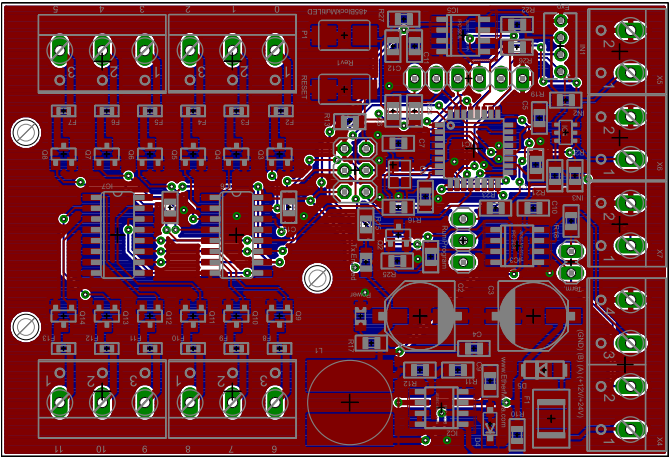
we are back on an previous project started by Marco Signorini from Ethermania, is the design of RS-485 boards. We are working with him in the general design of features and components, and working on a collision avoidance driver for vNet, inspired by uLAN.
We are not planning to change the design, because we are taking things simpler as we can. But gives here your comment, so that will inspire the next release.
http://www.souliss.net/2013/09/usart-driver-for-vnet.html#more
Regards,
Dario.

Jbllea
Di Maio, Dario
Regards,
Dario.
Jbllea
Dario Di Maio
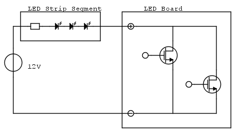
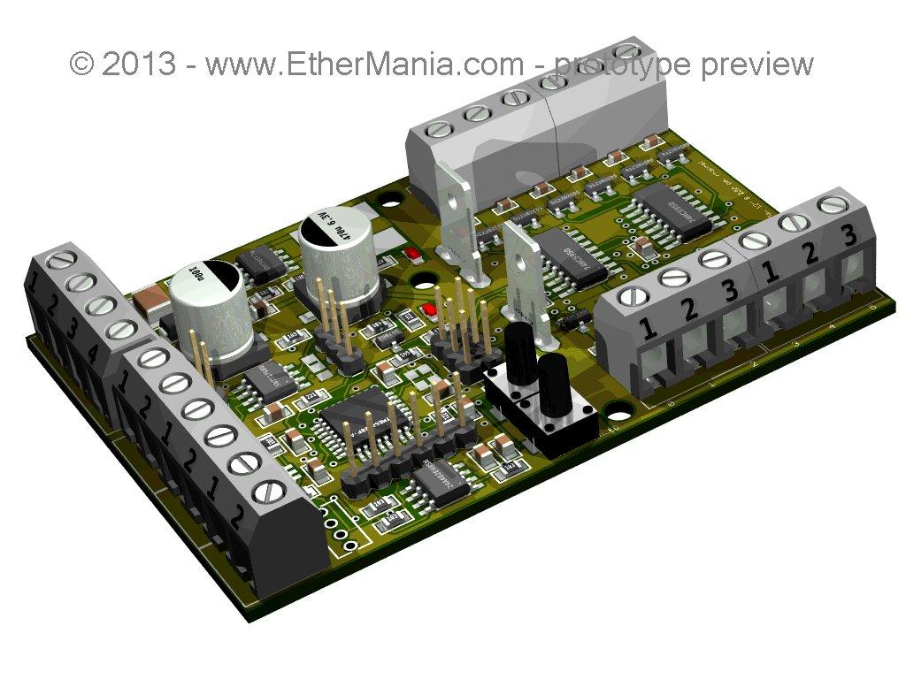
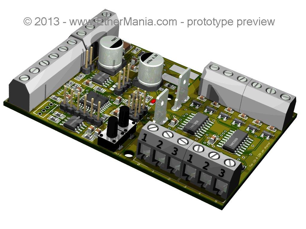
There are 12 MOSFET in open-drain configuration with a protective fuse for a maximum rate of 2.5A per channel and 3 digital inputs that can be connected directly to a standard wall swtich without any additional external component.
Enjoy and give us feedbacks.
Regards,
Dario.

Flavio P.
--
You received this message because you are subscribed to the Google Groups "souliss" group.
To unsubscribe from this group and stop receiving emails from it, send an email to souliss+u...@googlegroups.com.
For more options, visit https://groups.google.com/groups/opt_out.
Di Maio, Dario
Dario.
Flavio P.
I think there are some difficult to insert the board on a 503, and you?
From Mobile Nexus
--
Di Maio, Dario
Dario.
Flavio P.
Why do you use rs485? and power 24v??? They require one or two cable.... I think you can use a switching with input 220v AC and 12 or 5v DC for output in the same dimension....
From Mobile Nexus
--
Di Maio, Dario
http://en.wikipedia.org/wiki/J1708
http://ww1.microchip.com/downloads/en/AppNotes/01230A.pdf
Flavio P.
--
You received this message because you are subscribed to the Google Groups "souliss" group.
To unsubscribe from this group and stop receiving emails from it, send an email to souliss+u...@googlegroups.com.
For more options, visit https://groups.google.com/groups/opt_out.
Di Maio, Dario
Dario.
Flavio P.
I didn't got the question. For the scope the 328 has enough RAM, in case of CAN there are microcontroller with a build in transceiver for CAN.
Is nice to see that if you have CAN, you haven't I2C. Both protocols are electrically quite similar, they works on a pulled line and drawn current to transmit data using an open-drain/collector device.
Dario.
--
You received this message because you are subscribed to the Google Groups "souliss" group.
To unsubscribe from this group and stop receiving emails from it, send an email to souliss+u...@googlegroups.com.
For more options, visit https://groups.google.com/groups/opt_out.
Di Maio, Dario
Yes, the wireless is also a way that can be taken in account, Atmel has a series of micro with built in 0.9 or 2.4 Ghz radio.
Some months ago I've discovered also uracoli that is a library for such micro, I've never used but it con be integrated as alternative to chibi one.
Regards,
Dario.
From mobile.
mc bit
--
You received this message because you are subscribed to the Google Groups "souliss" group.
To unsubscribe from this group and stop receiving emails from it, send an email to souliss+u...@googlegroups.com.
For more options, visit https://groups.google.com/groups/opt_out.
Di Maio, Dario
I'm still waiting for the free samples that they promised me... arghhh :)
I've a couple of Zigduino for testing the stack that use the same family of microcontroller.
Dario.
From mobile.
Flavio P.
I'm still waiting for the free samples that they promised me... arghhh :)
Dario.
From mobile.
--
You received this message because you are subscribed to the Google Groups "souliss" group.
To unsubscribe from this group and stop receiving emails from it, send an email to souliss+u...@googlegroups.com.
For more options, visit https://groups.google.com/groups/opt_out.
Di Maio, Dario
Actually we support chibiduino, that is same of Zigduino but with the radio not embedded into the micro.
I've not yet tested the Zigduino due to lack of time, but after the last bugfix that we have done on the stack, chibiduino is pretty reliable.
Me too I like wireless but some people are scared about.
Dario
Dario.
From mobile.
Flavio P.
Actually we support chibiduino, that is same of Zigduino but with the radio not embedded into the micro.
Dario.
From mobile.
--
You received this message because you are subscribed to the Google Groups "souliss" group.
To unsubscribe from this group and stop receiving emails from it, send an email to souliss+u...@googlegroups.com.
For more options, visit https://groups.google.com/groups/opt_out.
Di Maio, Dario
Dario.
Flavio P.
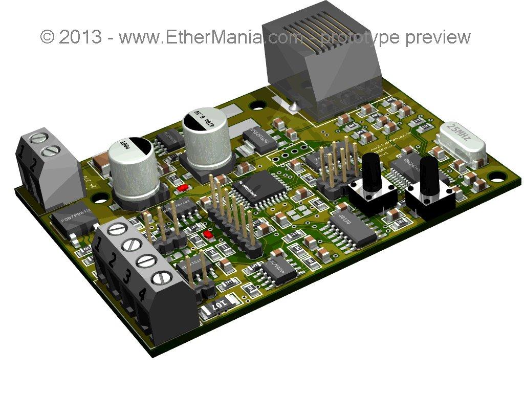
I like wireless, but RS485 is cheaper and doesn't scare people about EMI. In the starting idea of Marco there was a bus wired connection, so we moved on that way, but a wireless board could be of interest.
Regards,
Dario.
--
You received this message because you are subscribed to the Google Groups "souliss" group.
To unsubscribe from this group and stop receiving emails from it, send an email to souliss+u...@googlegroups.com.
For more options, visit https://groups.google.com/groups/opt_out.

EtherMania
Di Maio, Dario
Yours are good discussion point that we can use for further release of the board.
Almost for the wireless that in my point of view is a plus.
Dario.
From mobile.
Flavio P.
Hello Marco,
I'm very pleased to know you! ;)
I'm not saying you are in a wrong way! I'm just thinking to a real application of a normal user....i think that an RGB strip in any normal home can be used only for scenic effect, but i agree with you to the RGB indicator! But 2,5A are wasted in this case....
RS485 are pretty good for me, and in my home the cable are waiting....but i'm ever thinking to a normale user....for the user cable=tecnician=money=less probability to use souliss!
I say for a wireless bus only for this reason....
From Mobile Nexus
Di Maio, Dario
Using Souliss you can even build a network mixed of many Rs485 links bridged wirelessly (a chiniduino and a 485 shield).
IMHO feedbacks help every time, no matter if the design in your mind doesn't mach with ours.
Is every time a treadoff :)
Dario.
From mobile.
EtherMania
I've understood your point and opinion and my answer has to be read in the sense of clarify what are the technical and feasibility reasons me and Dario based our choices.
For what is related to the RGB indicator I think there is a misunderstanding. There will be a third type board without MOSFET but with three RGB LEDS already mounted on it (or accessible through pin-headers). So there is no need to buy a 12 channel MOSFET featured for the sole purposes to have LED indicators. The board will be cheaper and smaller than the MOSFET based one, so it will easily fit on the back of a standard push buttons in a 503 sized box. I'm working these days on it so probably more details will follow in a few days/weeks.
My general idea is to start to propose something real and ready to be programmed for two reasons: the one is that I need to install some of these boards in my house... the second is because I like to do this and I need to find the funds to continue to do it.
So feedbacks are welcome and my consultancy job is to aggregate them in a something either technically then economically and time-limited feasible.
Thanks!
Marco Signorini
Di Maio, Dario
Flavio P.
For my actual job we was looking for absorption of FGS horn and bells to be drived with an open drain MOSFET. As is designed the board, you can even use more channel in parallel, up to drive a mega LED at 12V and 30A :)Dario.
--
You received this message because you are subscribed to the Google Groups "souliss" group.
To unsubscribe from this group and stop receiving emails from it, send an email to souliss+u...@googlegroups.com.
For more options, visit https://groups.google.com/groups/opt_out.
Di Maio, Dario
Flavio P.
--
You received this message because you are subscribed to the Google Groups "souliss" group.
To unsubscribe from this group and stop receiving emails from it, send an email to souliss+u...@googlegroups.com.
For more options, visit https://groups.google.com/groups/opt_out.
Dario Di Maio
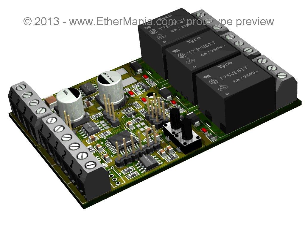
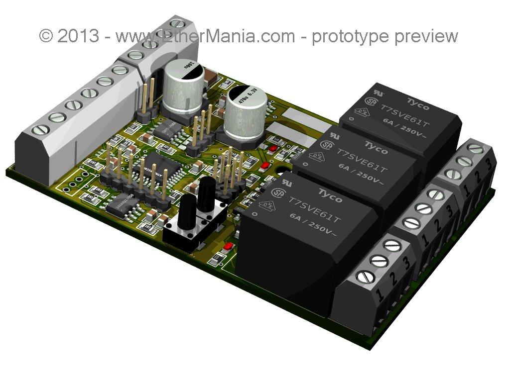
http://www.souliss.net/2013/09/3d-rendering-for-new-rs-485-boards.html#more
Regards,
Dario.
On Saturday, September 14, 2013 10:03:22 AM UTC+2, Dario Di Maio wrote:
Hi,
we are back on an previous project started by Marco Signorini from Ethermania, is the design of RS-485 boards. We are working with him in the general design of features and components, and working on a collision avoidance driver for vNet, inspired by uLAN.
We are not planning to change the design, because we are taking things simpler as we can. But gives here your comment, so that will inspire the next release.
http://www.souliss.net/2013/09/usart-driver-for-vnet.html#more
Regards,
Dario.

Alessandro
--