New baud rate via custom clock

Mild Lee Interested
I am interfacing an old "video terminal" with a max baud rate of 19200. I figure I can achieve this baud rate by "under clocking" the machine to 1/6 speed with a 1.2288 MHz clock (With, of course, the added effect that the whole machine will now run v e r y s l o o o o o w l y....)
I've got some scattered experience with digital logic but I'm a novice at clock circuits, so I started looking for a 1.2288 MHz crystal and quickly found that such a thing is not exactly common. Instead, I'm building a divide-by-6 frequency divider with 74HCT74 flip flops. My design uses 3 flip flops as a Johnson counter to divide by 3 and then one addition flip flop to divide by 2. The standard RC2014 clock module will provide the input clock signal.
The simulations look fine, but I was wondering if anybody else has implimented something similar and could suggest any pitfalls with this design.
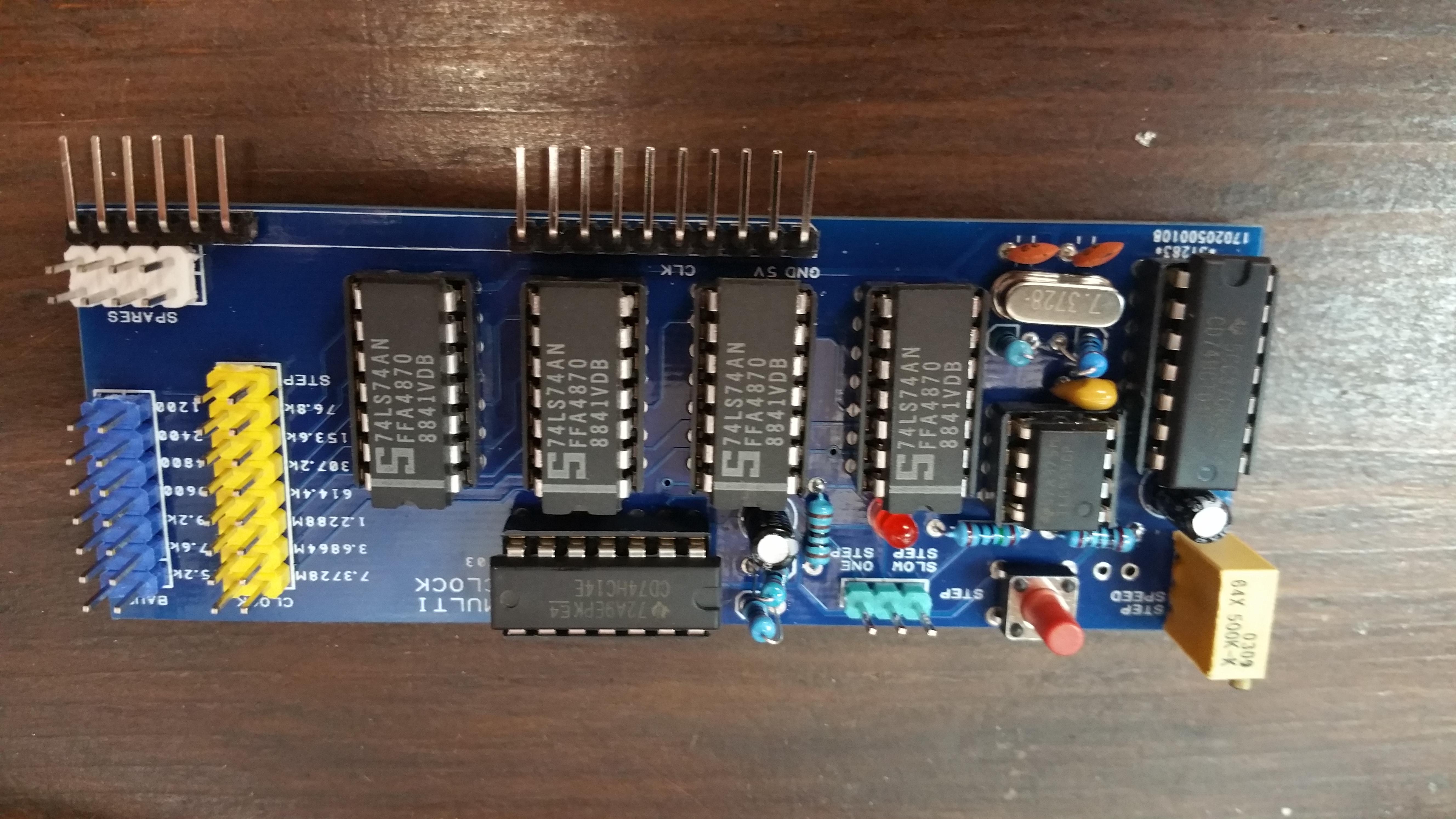
Here is an image of the circuit
My final goal will be to have a "clock modifier" PCB of chained filp-flops where different divisions can be selected by jumper or DIP switch.

Spencer Owen
--
You received this message because you are subscribed to the Google Groups "RC2014-Z80" group.
To unsubscribe from this group and stop receiving emails from it, send an email to rc2014-z80+unsubscribe@googlegroups.com.
To post to this group, send email to rc201...@googlegroups.com.
To view this discussion on the web, visit https://groups.google.com/d/msgid/rc2014-z80/c795636b-0fbc-40bb-a885-e4372e3d98b5%40googlegroups.com.
For more options, visit https://groups.google.com/d/optout.

Scott Lawrence
To view this discussion on the web, visit https://groups.google.com/d/msgid/rc2014-z80/CAO93Pte0csPq%2BTHx8XWDs6XNv83Z_5hCXRcdS9%2BZh4rMKJEhDQ%40mail.gmail.com.
Mild Lee Interested
In any case, the terminal I'm trying to interface must have hardware flow control to receive for anything over 1200 baud, so I am also planning to to break out pin 24 (Clear To Send) and put this through the spare channel on the MAX232 to be driven low by the "Clear To Receive" signal from the terminal.
All this falls in a heap if the MCU just ignores the interupt request and simply puts new data on the data bus at regular intervals, assuming that the transmission is complete. Can't be that dumb, right? I don't know anything about how the serial communicatin is implimented, so just hoping this aspect works how I think it does...
Regarding Spencers post about a slow clock, I'm with you there! My planned "under clocking" board will have selectable frequency dividers, but also something for stepping through operations at 1Hz or less. A simple 555 circuit would do the job, I think?
Mild Lee Interested
Available Frequencies and baud rates:
7.3728MHz / 115200 baud
3.6864MHz / 57600 baud
1.2288MHz / 19200 baud
614.4KHz / 9600 baud
307.2KHz / 4800 baud
153.6KHz / 2400 baud
76.8KHz / 1200 baud
There is also a "slow clock" using a simple 555 circuit that gives a clock rate that can be varied between about 4.6kHz and around 1.25Hz (not a typo: Hz - not kHz) and a push button for single stepping.This is all based on simply changing the clock speed. I'm absolutely sure that there is a more "correct" way to achieve this, but my RC2014 works absolutely fine using this board at all available frequenies and baud rates.
There are a couple of errors on the PCB pictured here that are fixed on the new version. I've also removed the RC2014 lable on the screen print on the new version as per Spencers standing request.
I'm writing up the project now and will add some links when it's complete.


Daniel Quadros
DQ
Spencer Owen
--
You received this message because you are subscribed to the Google Groups "RC2014-Z80" group.
To unsubscribe from this group and stop receiving emails from it, send an email to rc2014-z80+unsubscribe@googlegroups.com.
To post to this group, send email to rc201...@googlegroups.com.
To view this discussion on the web, visit https://groups.google.com/d/msgid/rc2014-z80/53bd1be7-9578-4705-9d66-08e2714b5d1c%40googlegroups.com.
Scott Lawrence
To view this discussion on the web, visit https://groups.google.com/d/msgid/rc2014-z80/CAO93Ptf%3D5kbLp%3D17ygvT6bGd0mwfxuT6WqQhZOMCbo25-hqbPA%40mail.gmail.com.
Mild Lee Interested
The first is that I'm just a beginner with the software side and don't know where to start!
The second is that I wanted to retain the standard RC2014 clock because I admire the efficency of design. Maybe it's common practice but choosing a master clock speed specifically to provide a standard baud rate without having to include a second clock struck me as pretty clever.
Third is that I didn't want to be limited to a slow master clock speed.
Mild Lee Interested
Once I've received the corrected version of the PCB and tested it, I'll make it available for order from DirtyPCBs. They are cheap and the quality is good (despide the name) but have a minimum order of 10 boards so that won't suit everybody.
I'll be happy to pass on a few of my 8 surplus boards at cost when they arrive and I'll set something up off this forum to do that.
As for making kits, I'd really like to do that but not sure I have the time to set it up and administer it. The parts are all cheap and readily available so if there is a demand, I'll probably sell the bare boards only - but packaged with instructions and a parts list.
Mild Lee Interested
The terminal is 80's vintage and until about 3 years ago it was the main HMI interface on operational production equipment (a coil steel cut-to-length line). I maintained the machine and salvaged the terminal and documentation when the machine was decommissioned.
I bought my RC2014 specifically to get it operational again.
There is almost no information about the VP3301 on line. I have included a crappy .pdf scan of
the user manual in my Github repository for this project. I've seen them on ebay now and then at stupid prices.
The terminal
features an early membrane keyboard, 8 bit sound and a composite video output in
NTSC format. Interfacing is RS232 or 4-20mA. Maximum baud rate is 19200 and it needs hardware flow control for anything over 1200 baud, so I had to do some additional hacking to the Serial IO board to break out the CTS signal on the ACIA through the MAX232. This will be included in the write up.
Unfortunately, its hardwired 7 data bits, not 8. I've got around this by setting the parity bit to space (7S1) which seems to pad it out enough to do the trick for plain text with the RC2014 (8N1) but I suspect will limit or prevent the use of control characters. I've not tried yet.

Paul Land
(Picture attached)
Paul Land

Steve Cousins
On Thursday, 31 May 2018 18:26:22 UTC+1, Paul Land wrote: