User Experience Module - PS/2 & VGA

Phillip Stevens
- Provide PS/2 Keyboard and VGA physical interfaces, so the RC2014 can be "stand alone".
- Emulate a ACIA or SIO serial device to provide a CONSOLE text mode video interface.
- Emulate a second ACIA or SIO TTY serial device on FTDI pin-out.
- Emulate a video device to enable 2D/3D vector graphics overlay (stretch goal).
- Emulate at least one sprite/tile mode for TMS9918 overlay (stretch goal).
What it is not designed to do:
- Support PAL/NTSC video (we're past that).
- Support sound (other modules do that).
- Support mass storage (other Modules do that).
- Complete TMS9918 emulation (there's the real thing).
Of course the gotcha here is that I've totally no experience writing Propeller assembly language.
But in 2017 it was the same for Z80. How hard can it be?
So this is a bit of a meaty longer term project.
Anyway, the hardware design is now done, and I'm about to hit up Seeed to get a PCB Built.
If anyone wants a PCB to experiment (particularly if you're in Australia/NZ) let me know.
In Northern Hemisphere, if you're interested drop me a note and I'll send you the Gerbers.
Enjoy, Phillip

Marco Maccaferri
> The design goals are to:
>
> be "stand alone".
> - Emulate a ACIA or SIO serial device to provide a CONSOLE text mode
> video interface.
> - Emulate a second ACIA or SIO TTY serial device on FTDI pin-out.
> - Emulate a video device to enable 2D/3D vector graphics overlay
> (stretch goal).
> - Emulate at least one sprite/tile mode for TMS9918 overlay (stretch
> goal).
Interesting project.
Don't know if you already seen that (don't remember if I have posted
something here):
https://www.maccasoft.com/electronics/vga-interface-for-rc2014-computer/
It is basically a VGA + ACIA emulation. It monitors only two ports but
with some changes I think it can monitor more ports.
I also have an almost complete TMS9918 emulation here:
https://github.com/maccasoft/propeller-graphics-card/tree/master/tms9918
Best regards,
Marco
Phillip Stevens
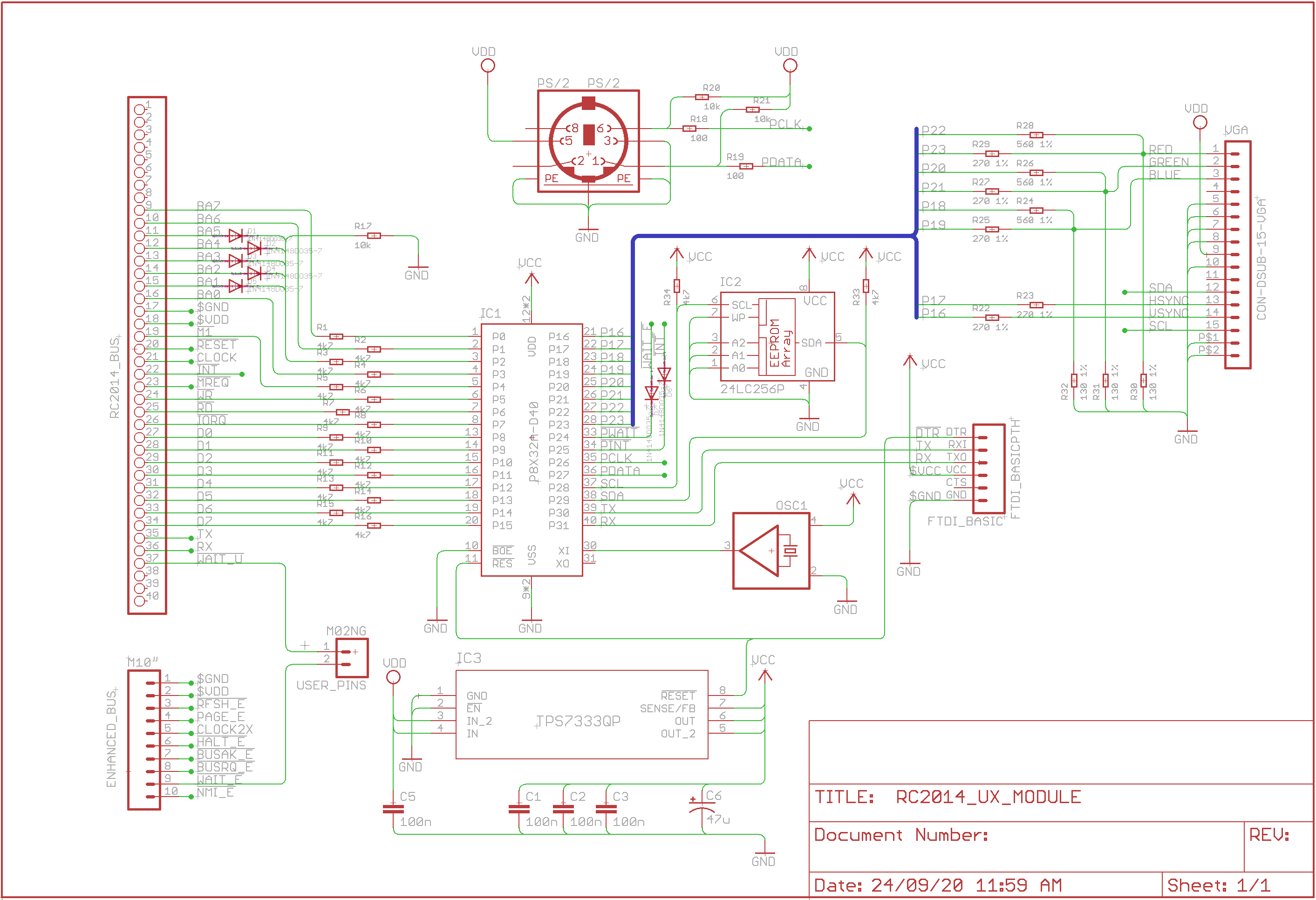
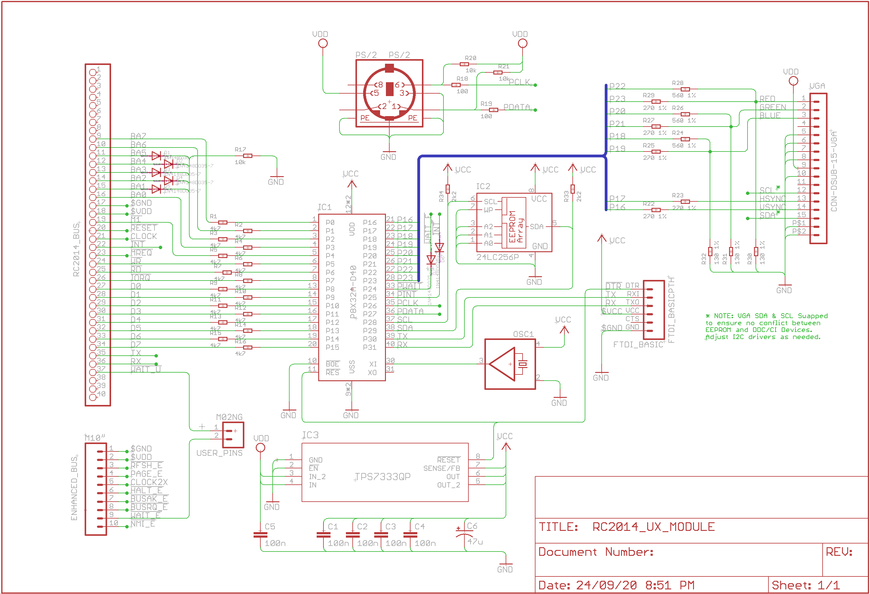
- Used A7, A6, (and A0) to allow major interfaces at 0x40 (video graphics mode), 0x80 (video serial text mode), and 0xC0 (tty second serial?).
- Preferred a PS/2 keyboard interface, because "retro" (I note you have both PS/2 and USB done).
- Pushed Tx/Rx interface back onto the bus.
- Connected /INT, so that the ACIA or SIO emulation can do IM1 / IM2 interrupts.
- Connected the VGA I2C interface, so that monitor info can be read (and possibly auto-adjust scanning).
- Used a 3v3 supply with integrated RESET delay.
- Removed the speaker to recover some I/O pins.
- Done the Tx/Rx to match FTDI pinout (rather than Propeller pinout).
Marco Maccaferri
> - Connected /INT, so that the ACIA or SIO emulation can do IM1 / IM2
> interrupts.
Not sure it can handle IM2, despite the fast clock, the instructions
requires 4 clock cycles and with all things to do it may not be fast
enough. At 80MHz it always need to assert the wait line to properly
present the data for an IN instruction, and it must be asserted very
quickly otherwise it will be sampled on the following instruction.
> - Removed the speaker to recover some I/O pins.
Audio can be done with one pin, if you manage to free one (maye IORQ
linked to the address lines ?), and there are emulators for AY3891,
SN76489 and even SID.
Hope it will not run out of cogs... :-)
Had only a quick look at the schematic and pcb, just a note: be sure to
have a bypass capacitor on both power pins otherwise the internal PLL
may be damaged.
> Have you done a "modern" vector graphics kind of interface previously? I'm
> thinking something like the FTDI EVE FT800 graphics devices. That style of
> GPU is perfect to implement with the Propeller, as there is no frame store
> needed, but rather a vector instruction store that holds information so the
> scan line can be generated dynamically just before it is displayed.
http://forums.parallax.com/discussion/171856/wip-beam-chasing-polygon-rasterizer
Best regards,
Marco
Phillip Stevens
Il 24/09/20 09:40, Phillip Stevens ha scritto:
Had only a quick look at the schematic and pcb, just a note: be sure to
have a bypass capacitor on both power pins otherwise the internal PLL
may be damaged.
> Have you done a "modern" vector graphics kind of interface previously? I'm
> thinking something like the FTDI EVE FT800 graphics devices. That style of
> GPU is perfect to implement with the Propeller, as there is no frame store
> needed, but rather a vector instruction store that holds information so the
> scan line can be generated dynamically just before it is displayed.
No, but this thread on the Parallax forum looks interesting.
http://forums.parallax.com/discussion/171856/wip-beam-chasing-polygon-rasterizer
Phillip Stevens
Had only a quick look at the schematic and pcb, just a note: be sure to
have a bypass capacitor on both power pins otherwise the internal PLL
may be damaged.Marco, thanks. You must be reading my mind...I spent 15 minutes (literally) looking at that capacitor, wondering whether it was needed, or not.I was going to ask, but you've given me the answer already.
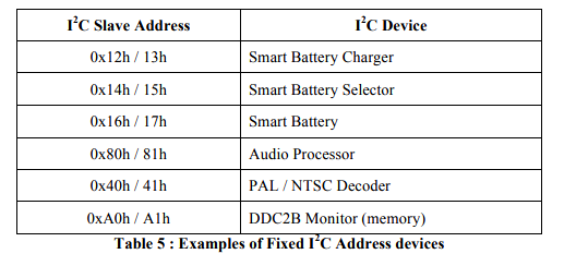
Since the EEPROM address (0xA0) is hardcoded into the Propeller ROM boot-loader, something needed to change.
P.

Chris Brunner
--
You received this message because you are subscribed to the Google Groups "RC2014-Z80" group.
To unsubscribe from this group and stop receiving emails from it, send an email to rc2014-z80+...@googlegroups.com.
To view this discussion on the web, visit https://groups.google.com/d/msgid/rc2014-z80/949658b7-f293-40bb-b35a-489b49f3941bo%40googlegroups.com.

Michael Stevens
To view this discussion on the web, visit https://groups.google.com/d/msgid/rc2014-z80/CALc%3DYoO7ivc56gObnNdTyF-39R4kGACjM-0HKpBLfh%2BMeTZBhQ%40mail.gmail.com.

Hans Hübner
To view this discussion on the web, visit https://groups.google.com/d/msgid/rc2014-z80/CANDE_bm7FHQpv_6%3DCcAcobQdZZV2EkQxTKMCuYu66BkU%2BG0B7A%40mail.gmail.com.
Chris Brunner
To view this discussion on the web, visit https://groups.google.com/d/msgid/rc2014-z80/CANDE_bm7FHQpv_6%3DCcAcobQdZZV2EkQxTKMCuYu66BkU%2BG0B7A%40mail.gmail.com.
Michael Stevens
To view this discussion on the web, visit https://groups.google.com/d/msgid/rc2014-z80/CALc%3DYoNxGJNDw3kztn6-150Lva8TLwABM%2BOXNVixAQzyhK%3DdSQ%40mail.gmail.com.

Bill Shen
My design is a monochrome 56 rows x 80 column text display named VGARC (VGA for RC2014). https://www.retrobrewcomputers.org/doku.php?id=builderpages:plasmo:vgarc
It uses two 4Kx8 dual port RAM to store text and font table. The video engine is based on a CPLD that generates the horizontal, vertical video timings, reads video text from the dual port RAM and looks up the corresponding font table to convert text to video bit stream. The other side of the dual port RAM is accessible by Z80 independent of the video engine. 8K bytes of text and font are directly addressable as contiguous I/O addresses (using 16-bit I/O addressing mode). Read and write access to the video text can occur anytime without affecting the quality of video display. If needed, the fonts can be change on the fly, but most of time it is loaded once after reset. Because access to each side of dual port can occur asynchronously and the dual port RAM have access time of 35nS, VGARC board can be accessed with zero wait from 7.37MHz to 22MHz and beyond. VGARC has spare I/O pins to accommodate PS/2 keyboard, but that was never implemented. Here is a YouTube video of Game of Life running on VGARC, https://www.youtube.com/watch?v=Bfs_Bu87qB8. The program is quite small, about 500 bytes, because it operates directly on the video text memory without the need of a separate data buffer. The video quality is not affected by the intensive Z80 read/write operations on the video data.
VGARC is not under active development, rather it is a stepping stone to my current all-in-one design called Z80ALL, https://www.retrobrewcomputers.org/doku.php?id=builderpages:plasmo:z80all:z80all_rev1 where Z80 is overclocked to VGA pixel clock of 25.175MHz and the display is downsized to 64 columns and 48 rows. I have the PS/2 keyboard working and is currently working on BIOS to implement a simple set of escape sequences.
Bill
Phillip Stevens


n.hae...@gmail.com

karlab
Phillip Stevens
Phil, nice module!
I have several of Marco's terminal module which I am very pleased with.What is the difference between your and Marco's module?The PS2 keyboard connector is obvious, but I am thinking more on the software part?
- Used A7, A6, (and A0) to allow major interfaces at 0x40 (video graphics mode), 0x80 (video serial high-res text mode), and 0xC0 (tty second serial?).
- Preferred a PS/2 keyboard interface, because "retro" (Marco has both PS/2 and USB done).
- Connected the keyboard/serial Tx/Rx interface back onto the bus.
- Connected /INT, so that the ACIA or SIO emulation can do IM1 / IM2 interrupts.
- Connected the VGA I2C interface, so that monitor DDC/CI info can be read (and possibly auto-adjust scanning to monitor capability).
- Used a 500ma 3v3 supply with integrated RESET delay.
- Removed the speaker.
- Done the Tx/Rx to match FTDI Basic pinout (rather than Propeller pinout).
- Set the base oscillator to 8MHz, so the Propeller Cogs run at 128MHz (rather than 80MHz).
Marco Maccaferri
> I'm wondering, will the VGA Serial Terminal Kit for RC2014 be
> re-issued on Tindie any time soon?
None of my products will be available anytime soon, at least not until
the pandemic crisis gets better (a lot better).
Best regards,
Marco
karlab
Marco Maccaferri
> I understand, you have had a pretty rough time in Italy. Is there any
> signs of improvement?
tomorrow, although not as hard as march-april. Luckily I'm in a zone
with a "moderate risk" without confinement rules, nevertheless I'll
limit the movements to the bare essentials anyway.
Best regards,
Marco
n.hae...@gmail.com

Wayne Warthen
This board is supported by RomWBW, but interfaces directlly via the bus (does not emulate ACIA, SIO, etc.). Regardless, you will find some decent code for VT100 terminal emulation as well as screen and keyboard interface examples for the Propeller.
Phillip Stevens
You may find some useful code in the RetroComp PropIO V2 project found at https://www.retrobrewcomputers.org/doku.php?id=boards:ecb:propio:start
This board is supported by RomWBW, but interfaces directlly via the bus (does not emulate ACIA, SIO, etc.).
But, on the other hand I'd like to have a capable graphics mode. Anyway graphics mode (sprite or vector based) is a stretch goal.
Regardless, you will find some decent code for VT100 terminal emulation as well as screen and keyboard interface examples for the Propeller.
Phillip Stevens
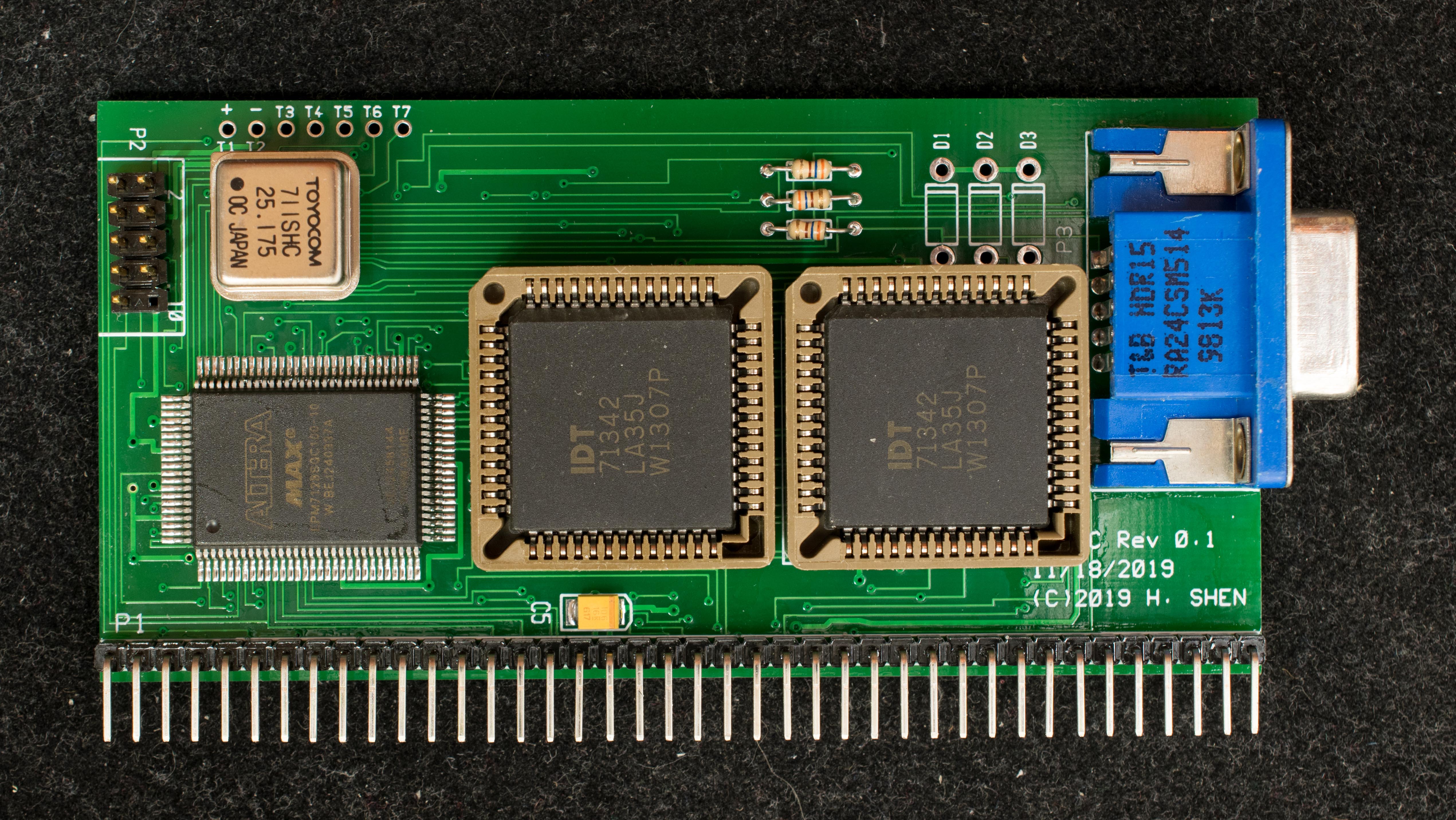
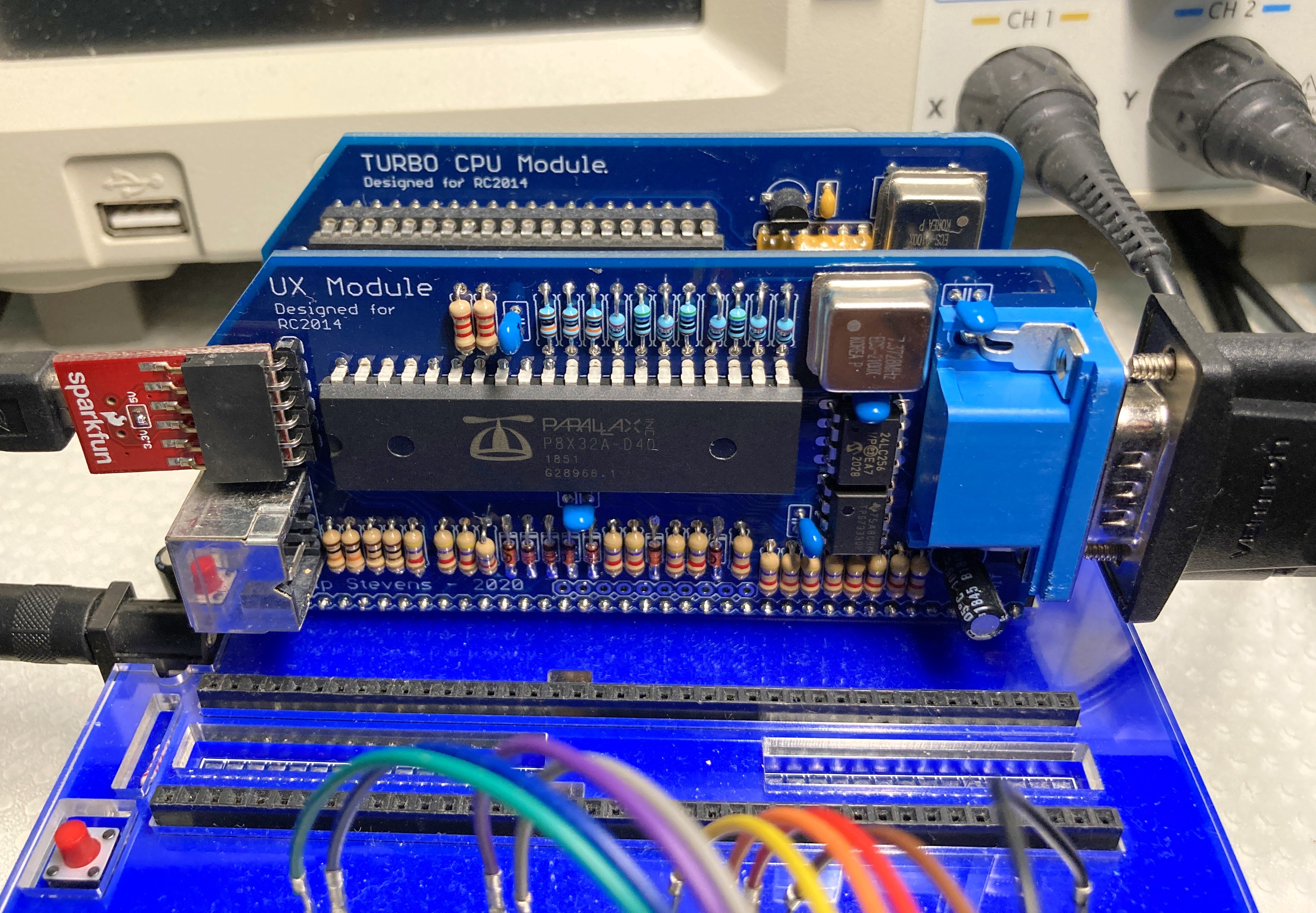
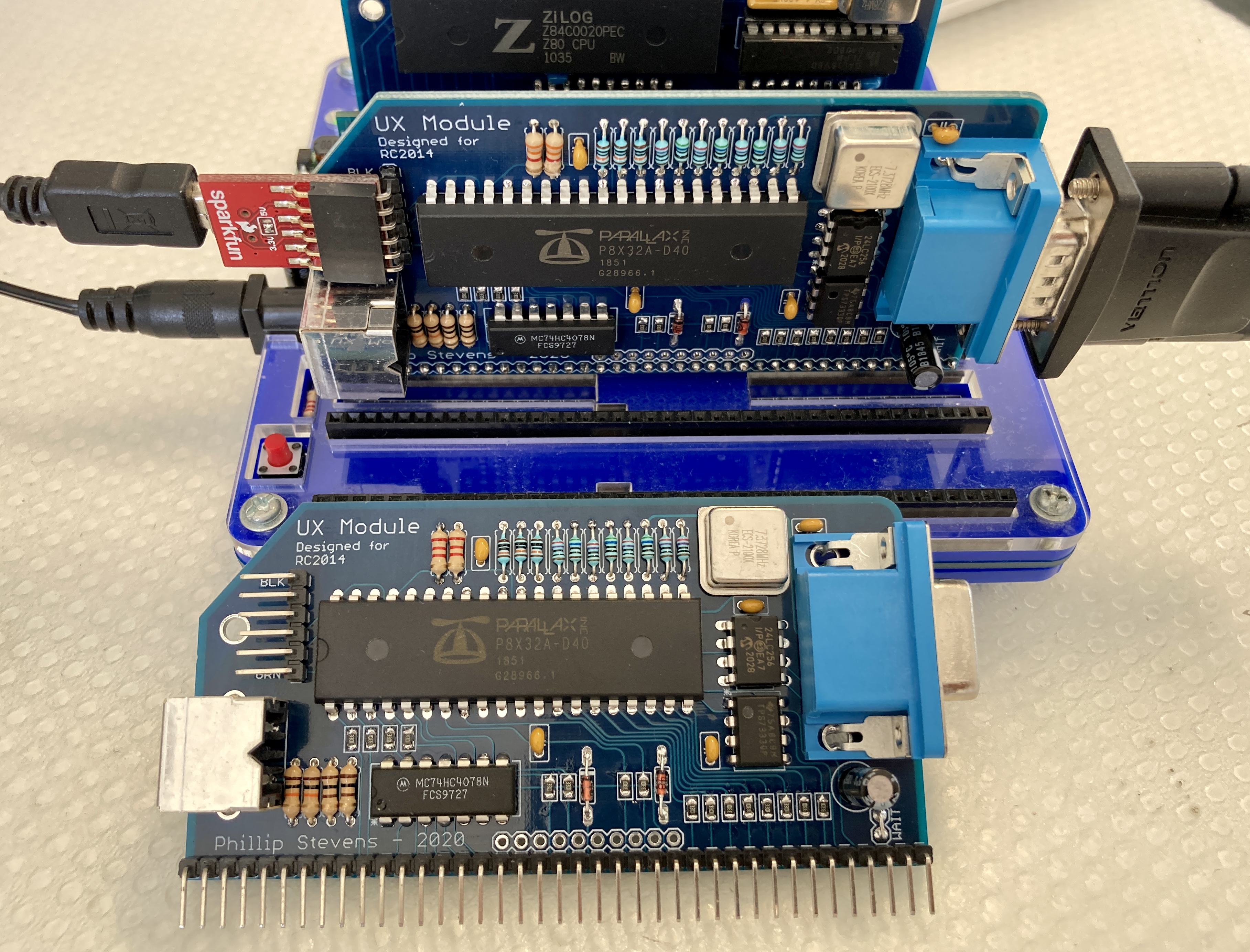
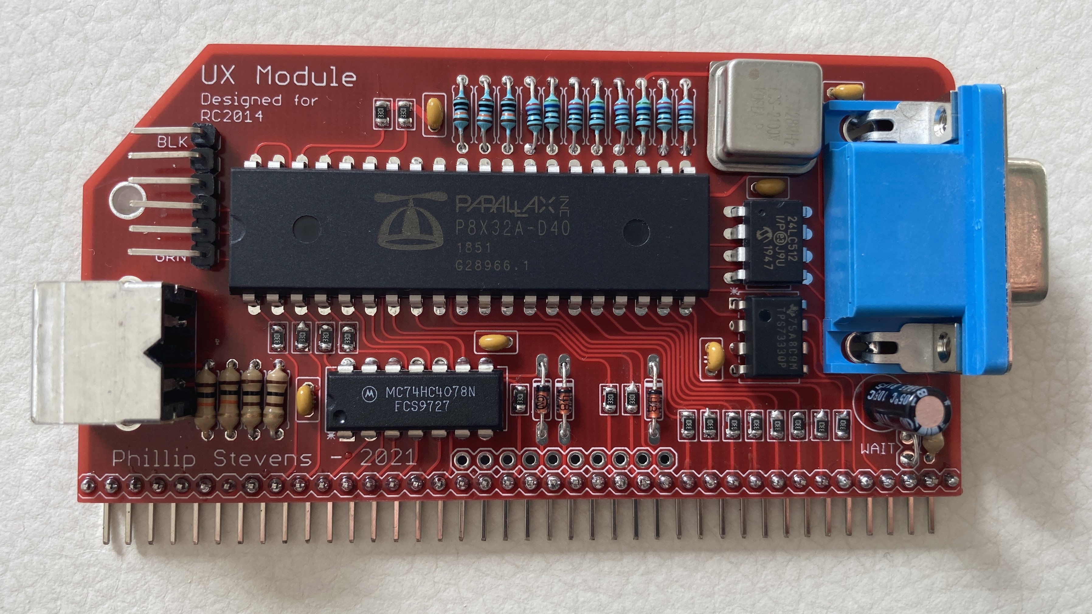
Following a short intermission, the UX Module has been assembled, and passed the smoke test and it also produced a "Hello World".This means that the FTDI serial interface, I2C EEPROM, Oscillator, and 3V3 power supply are all working as expected.The rest, as they say, is "just software".

This is 640x480 demo (squashed onto a shared screen with my workstation.
It is using the internal font stored as part of the system ROM, so there is no need to fill the user ROM with additional fonts.

I've got a VGA->HDMI adapter from Vention on AliExpress. It works as expected (which is lucky).
Because this first module was for testing, I left the resistors on the VGA outpu standing proud a little.
This makes hooking test probes easier.
Now, to take a step back and work out how these pieces will play nicely together.
P.
Phillip Stevens
Following a short intermission, the UX Module has been assembled, and passed the smoke test and it also produced a "Hello World".This means that the FTDI serial interface, I2C EEPROM, Oscillator, and 3V3 power supply are all working as expected.The rest, as they say, is "just software".


Colin MacArthur
Colin MacArthur
Wayne Warthen
You may want to check out the !WAIT circuit on Wayne's board. I believe it was added because the PROP could not respond fast enough...(Wayne please correct me if I am wrong)...
Phillip Stevens
You may want to check out the !WAIT circuit on Wayne's board. I believe it was added because the PROP could not respond fast enough...(Wayne please correct me if I am wrong)...
Colin, you are correct. The PropIO v1 did not have the !WAIT circuit and could only handle CPU speeds of about 6MHz. The new !WAIT circuit (on PropIO v2) is effective up to about 16MHz in my testing.
Wayne Warthen
I think that the Z80 /WAIT has to be generated after the /IORQ in no more than 1.5 clocks minus a small amount. Let's go with one clock cycle to be safe.So with with a 41ns /WAIT response, this solution should be good up to around a 20MHz Z80 system bus. Certainly safe at our RC2014 standard bus.
The PROPIO code uses the WAITPEQ instruction to check for IO states. This is the Propeller's secret weapon to manage IO really fast. Essentially you pend a "cog" until a set of pins (programmatically masked) match a state you programatically determine. This way the cog can respond instantly to an "interrupt" generated by a multi-pin state you prefer. But, the PROPIO code doesn't use the WR Effect with WAITPEQ, from what I read.
Colin MacArthur
Phillip Stevens
You may be on to something...I hope it works as it would reduce the part count & board size...Keep us posted
Marco has taken this one step further with his VGA Module code, and used a documented side effect of the WAITPEQ instruction to also trigger the /WAIT line IN THE SAME INSTRUCTION.By using the OUTA register (controlling the IO pin value) as the comparison with the input registers, and the WR Effect the /WAIT pin gets toggled on match.Anyway, there's a whole thread on using WAITPEQ with WR Effect on the Propeller Forum if you're interested to read deeper.
Phillip Stevens
Phillip Stevens
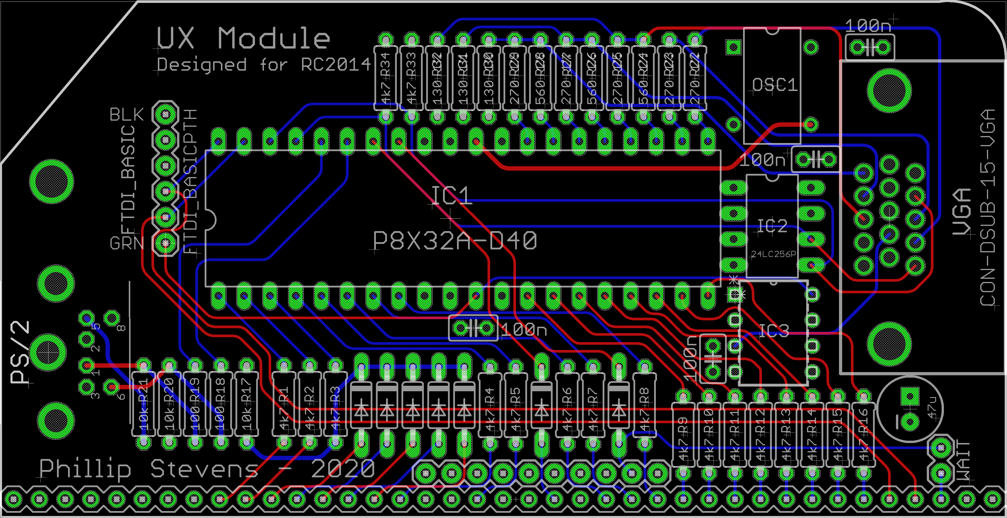
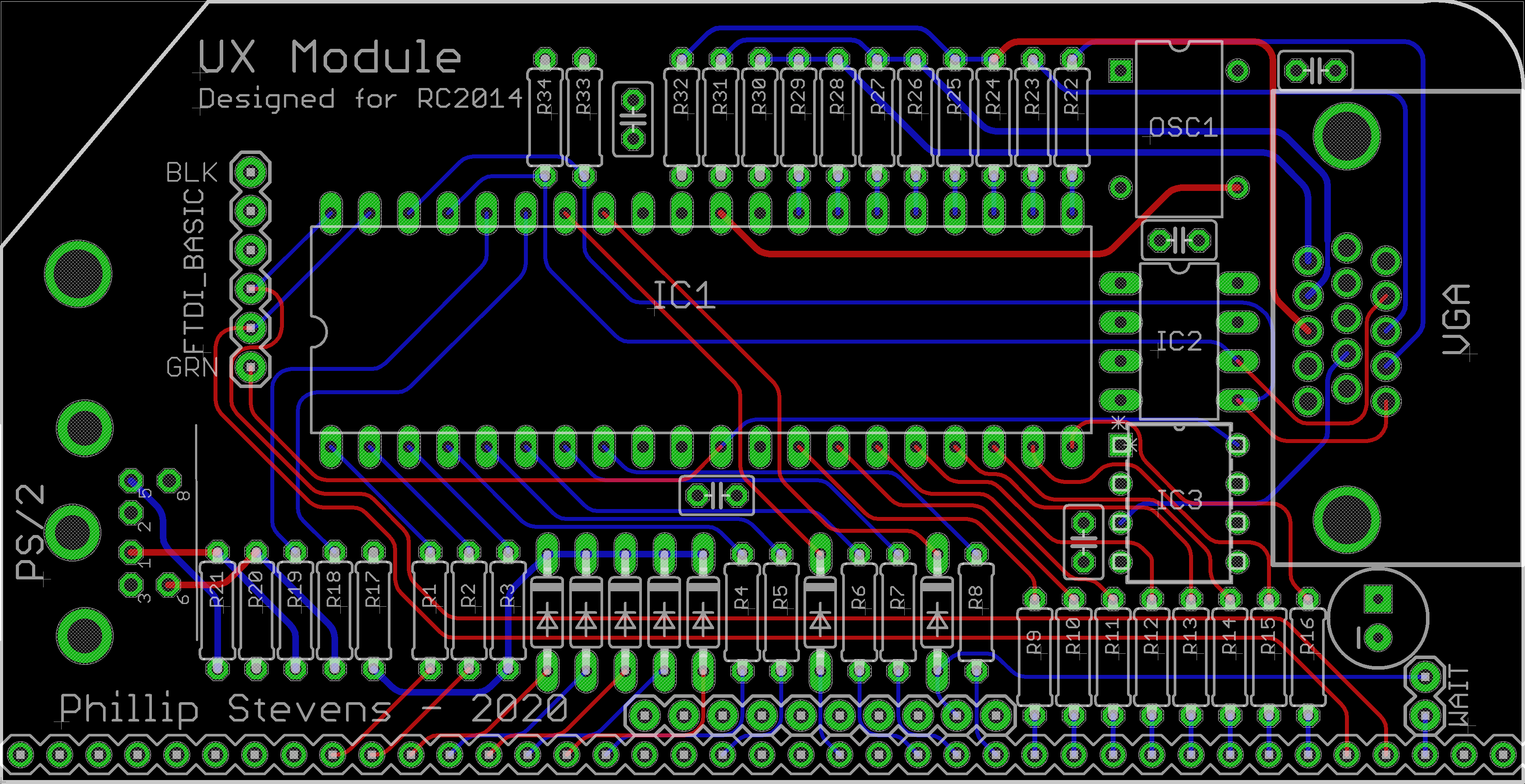
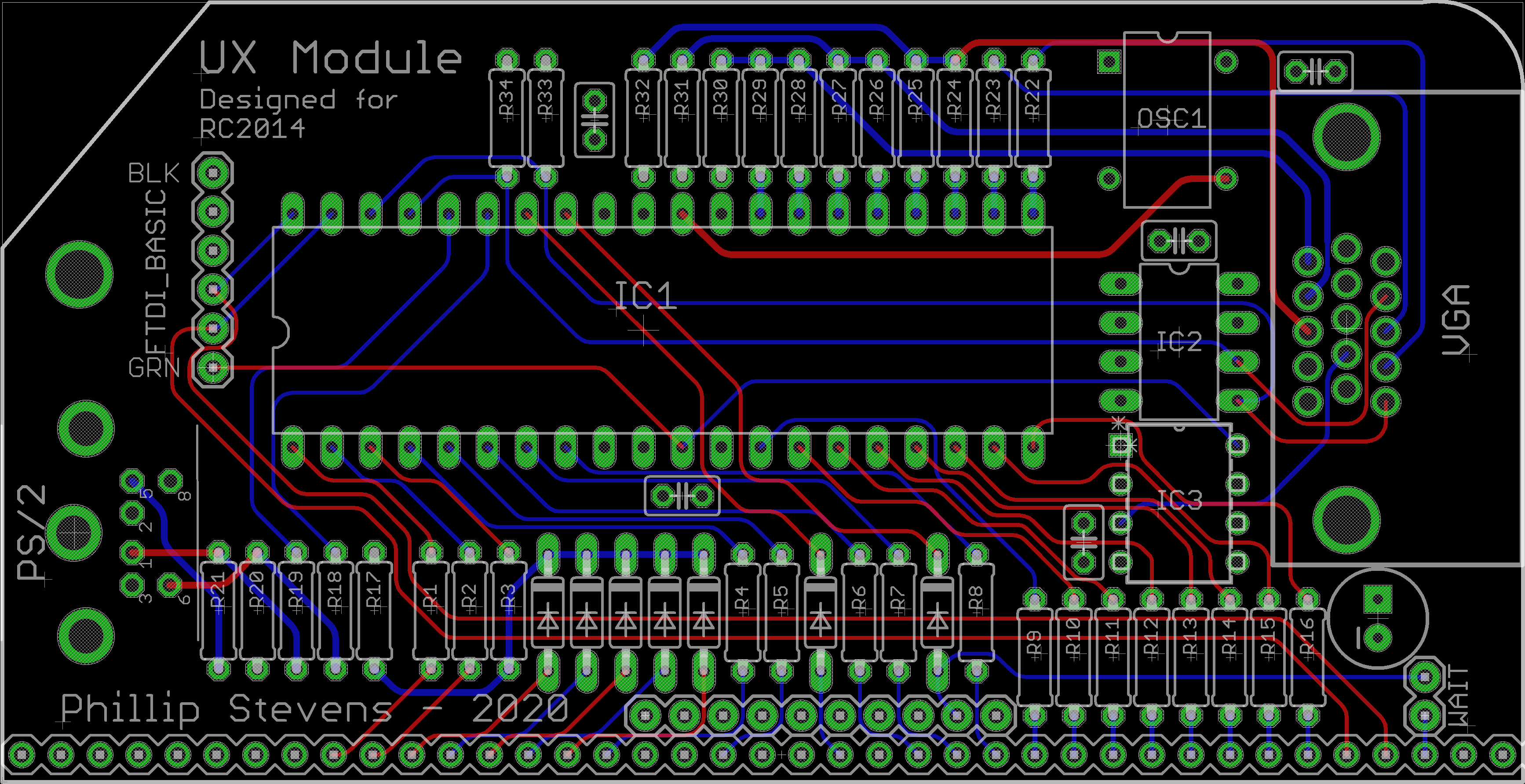
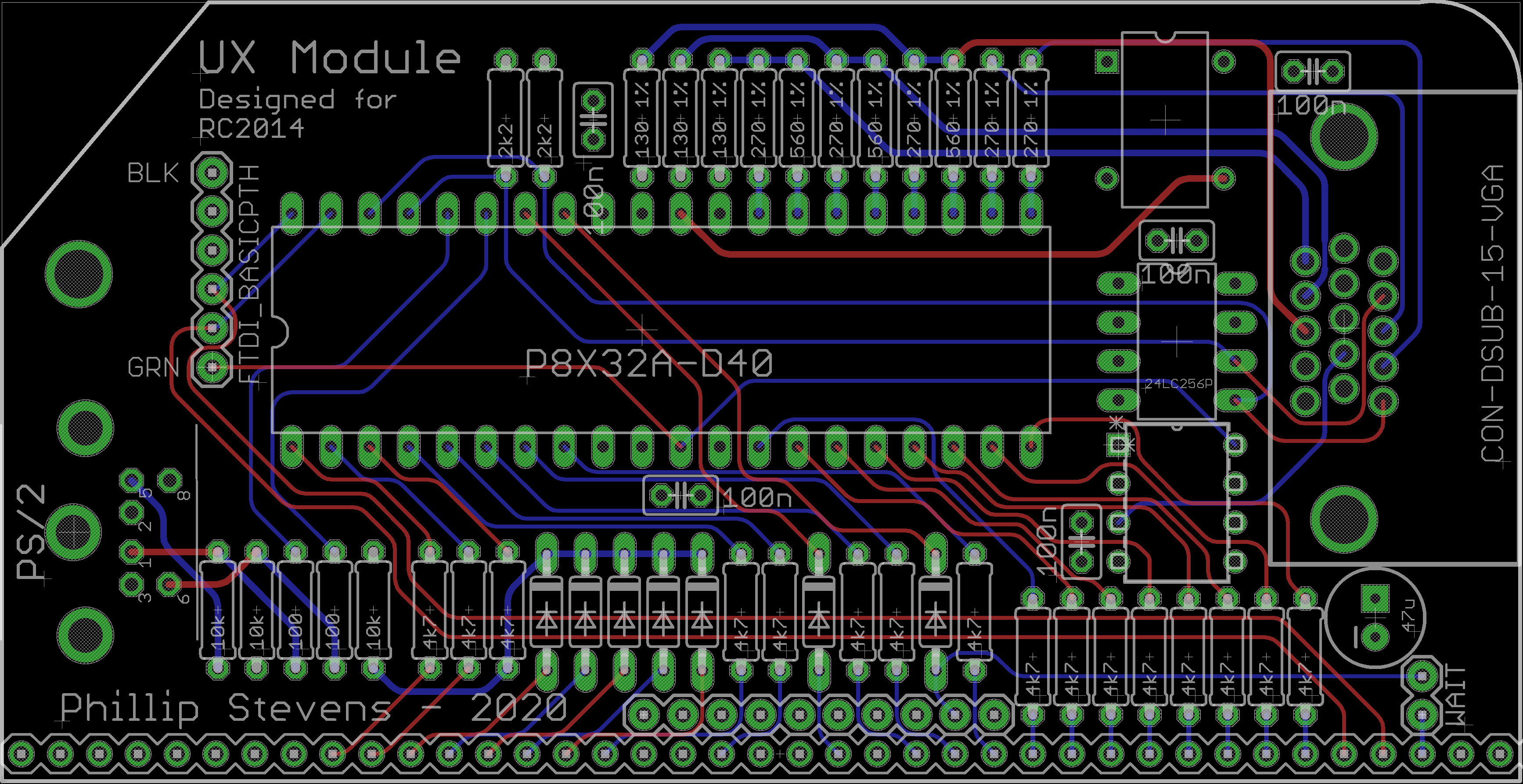
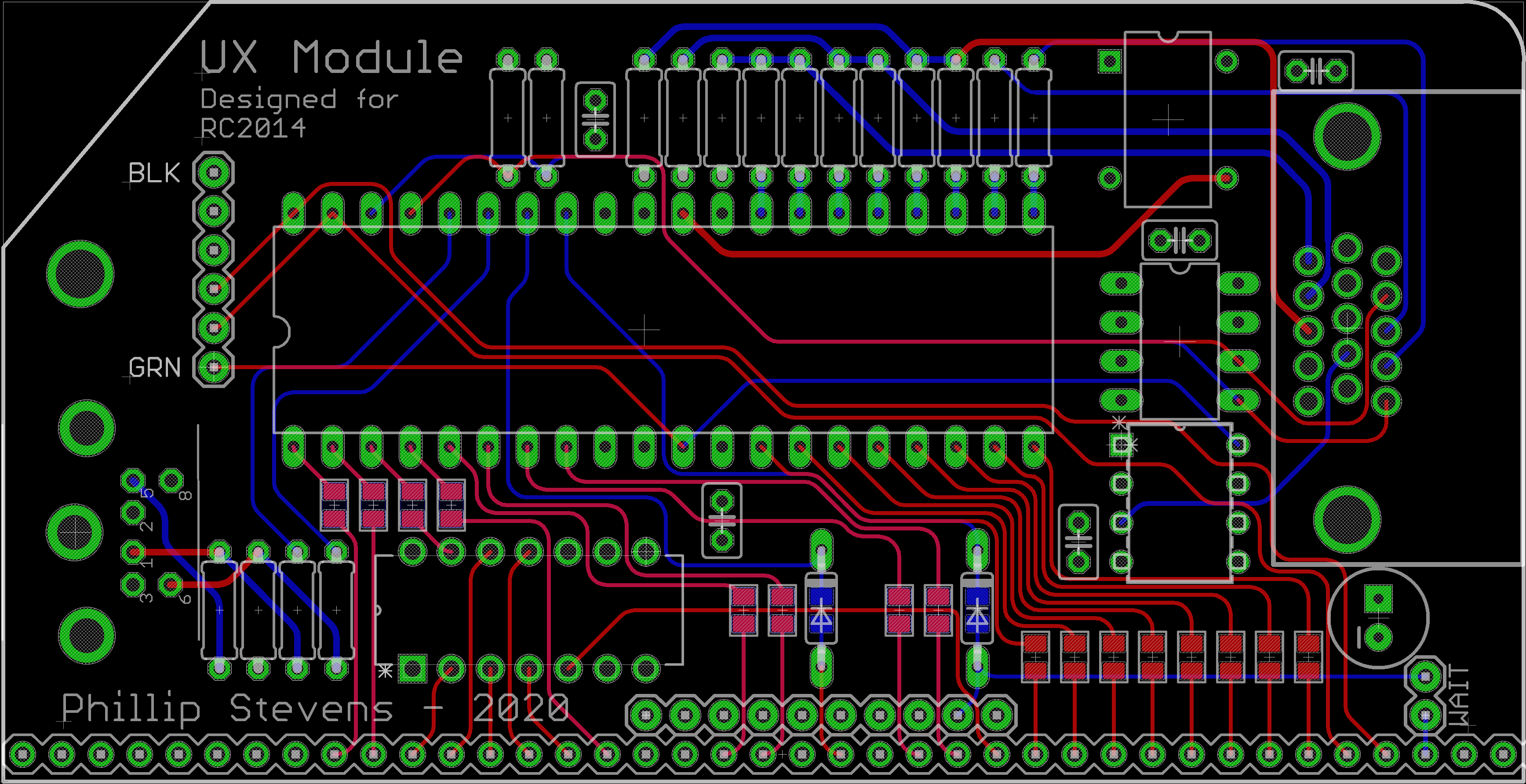
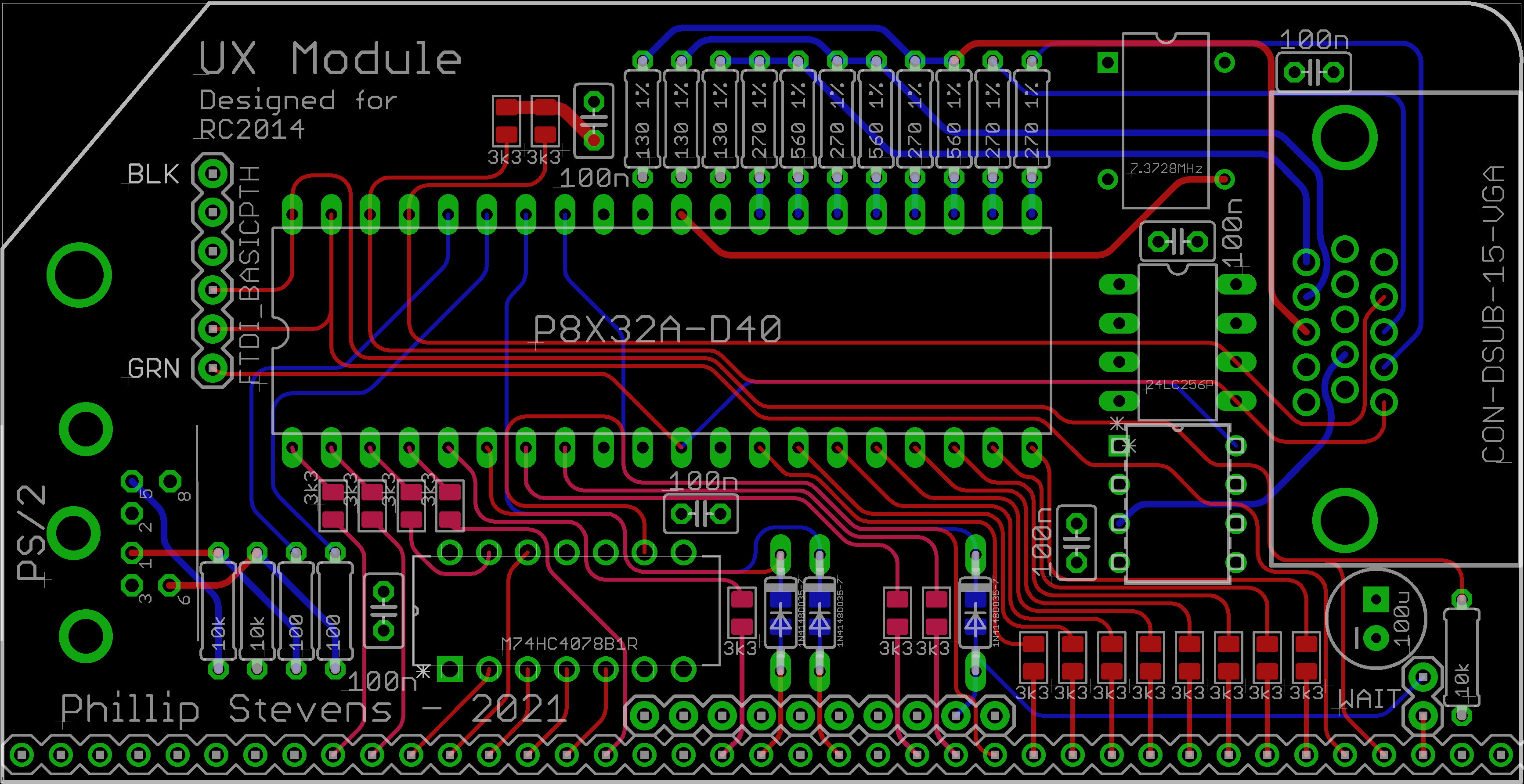
- using large 0805 SMD for some of the resistors and capacitors (hidden on the back of the PCB) - makes the layout less messy.
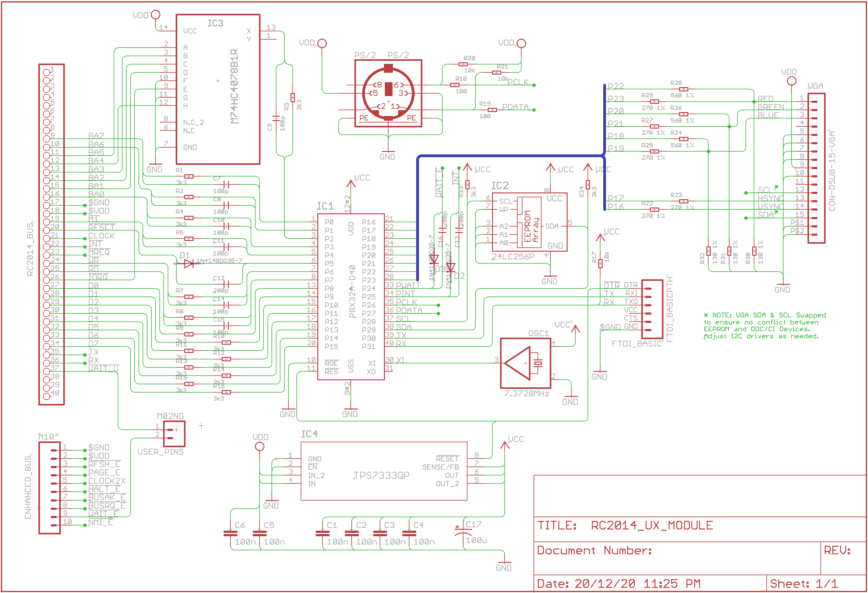
- using a 74HC4078 NOR gate to capture all of the low address lines and /IORQ into one Propeller input pin, unloads the address bus (compared to diode logic).
- using one freed input pin for the Z80 reset, to allow the UX Module to restart the Z80 (CTRL-ALT-DEL from keyboard).

djrm
Phillip Stevens
I'm using a Vention VGA-HDMI converter. They cost about $8, and do the job excellently.
Phillip Stevens
Done another iteration on the UX Module PCB.The major changes are
- using large 0805 SMD for some of the resistors and capacitors (hidden on the back of the PCB) - makes the layout less messy.
- using a 74HC4078 NOR gate to capture all of the low address lines and /IORQ into one Propeller input pin, unloads the address bus (compared to diode logic).
- using one freed input pin for the Z80 reset, to allow the UX Module to restart the Z80 (CTRL-ALT-DEL from keyboard).
Github UX Module Repository here.
Phillip Stevens
Phillip Stevens wrote:Done another iteration on the UX Module PCB.
Github UX Module Repository here.
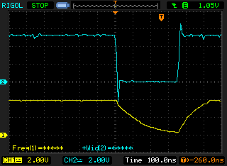
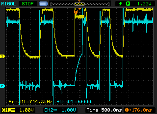
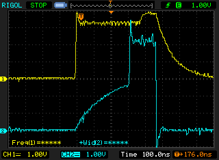
I finished testing on a "small" MS Basic (Classic) RC2014 and moved on to testing with a larger CP/M based system. And uncovered a few more issues.Firstly, I initially selected 1nf capacitors for the control lines. These are too large and loaded up the control lines too much. I've since reduced them to 200pf, and perhaps will drop even further before finishing. The waveforms still look good with 200nf, so it would be possible to go even lower value.
I found an issue with the /WAIT line not working properly with the APU Module. Reading further discussions it would be good to entirely remove capacitance from the three Propeller output lines (/RESET, /INT, and /WAIT). I've now got some "digital" transistors to experiment with. These digital transistors are pre-biased (on substrate). This keeps the component count low, as the bias resistors are integrated into the package. They act as open collector inverter gates, so I'll need to reconfigure the bus software to suit. To be continued.
And finally, I've found that the resistor only solution for the data bus pins is quite slow with respect to the Z80 bus.
I'm resolving the issue now by putting one or more nop instructions in the code to allow the bus to settle after writing, but I feel the better answer would be to use parallel capacitance too.But, that means 8 additional components to weigh against just adding one or two nop instructions. Decisions... decisions... decisions.
- converting the /RESET line to diode + capacitor logic.
- pulling up the RX line to avoid noise when the FTDI interface is unplugged.
- adjusting the input/output capacitance.
Phillip Stevens
So the final design is now "finished" as far as I'm concerned. In the end, the only substantial changes were:
- converting the /RESET line to diode + capacitor logic.
- pulling up the RX line to avoid noise when the FTDI interface is unplugged.
- adjusting the input/output capacitance.
Merry Christmas, Phillip
Chris Brunner
--
You received this message because you are subscribed to the Google Groups "RC2014-Z80" group.
To unsubscribe from this group and stop receiving emails from it, send an email to rc2014-z80+...@googlegroups.com.
To view this discussion on the web, visit https://groups.google.com/d/msgid/rc2014-z80/730d219a-7c62-4866-b9fb-a96793310200n%40googlegroups.com.
Phillip Stevens
That's exciting! I have a couple questions though:1) Is the firmware complete? Does it come pre-flashed?
2) I don't see the boards on Tindie. Is that link correct?
Chris Brunner
--
You received this message because you are subscribed to the Google Groups "RC2014-Z80" group.
To unsubscribe from this group and stop receiving emails from it, send an email to rc2014-z80+...@googlegroups.com.
To view this discussion on the web, visit https://groups.google.com/d/msgid/rc2014-z80/61498829-745f-432e-9427-71ab1eadb156n%40googlegroups.com.

Wuerfel21
Also I hope that we can get vector graphics running too.
Phillip Stevens
I've put the Christmas release UX Module PCBs on Tindie now. There are two options, 1. with SMD soldered and including 74HC7048, or just the 74HC7048. The base for the PCB only.

Phillip Stevens
Finally added to the documentation for the UX Module.
Added a BOM, usage instructions, and programming tips.
I've put the Christmas release UX Module PCBs on Tindie now. There are two options, 1. with SMD soldered and including 74HC7048, or just the 74HC7048. The base for the PCB only.

Clark Martin
Phillip Stevens
You could cut a trace and mount either a switch or jumper.
> And so it seems the only workable solution seems to be add a hardware switch to disconnect the DTR line for normal use.
Marco Maccaferri
> Even easier, an my interim solution is just to bend the DTR pin out
> a little so it doesn't insert into the FTDI Basic socket. But it
> still means a new PCB, and the waste bin for the current design PCBs
> (of which I have quite a few). :-(
/bin/stty -F /dev/ttyUSB0 -hupcl
The programs accessing the serial can still toggle DTR on their own, but
at least this disables the automatic toggle. Wondering why doesn't work
for you.
Using Ubuntu 20.10.
Best regards,
marco
Phillip Stevens
As I wrote on the Parallax forum, the stty solution works for me:
/bin/stty -F /dev/ttyUSB0 -hupcl
The programs accessing the serial can still toggle DTR on their own, but at least this disables the automatic toggle. Wondering why doesn't work for you.
Phillip Stevens
Phillip Stevens
Wayne Warthen
Because of the way that RomWBW detects serial devices, the SIO ports will be detected first, causing them to become Char 0 and Char 1. As Char 0 is the boot console, nothing is going to appear on the VGA screen console. So, we need to rearrange the detection to ensure the UX Module (detected as ACIA) is forced to be the console port. This is done with the (as yet undocumented) FORCECON configuration. Assuming we have one SIO Module with 2 ports discovered before the UX Module ACIA port we want FORCECON set to 2.
Phillip Stevens
Phillip wrote:Assuming we have one SIO Module with 2 ports discovered before the UX Module ACIA port we want FORCECON set to 2.
The most recent update to RomWBW in the GitHub dev branch has a bit of a cleanup with respect to the FORCECON setting. The underlying mechanism for setting the boot console device has been simplified and a "proper" configuration variable is now available.
This needs to be changed to:
BOOTCON .EQU 0 ; BOOT CONSOLE DEVICE
Wayne Warthen
Wayne Warthen
In other news, an early release video of VECTOR Graphics (VJET) on the UX Module, all thanks to Wuerfel_21 (of SPIN HEXAGON fame).Next step is to create a Z80 GL to make it easy to use on RC2014.Wooo! Triangles! youtu.be/eN1TrmOITD8
Phillip Stevens
Phillip Stevens
The UX Module also has a FTDI standard serial interface, used for programming the Parallax Propeller MCU rather than the Prop Plug interface found on most Propeller based PCBs. This serial interface can also be used for operating the RC2014, simultaneously with the VGA + PS/2 interface.
The UX Module can also be used as a stand-alone Parallax Propeller MCU module, with most of the bus pins brought out to a RC2014 style bus interface, opening the door to program other applications either within the RC2014 environment or completely independent of the RC2014.
On Monday 15 March 2021, Phillip Stevens wrote:
It is hard to top the success that Wuerfel_21 had with the Spinning Triangles, but let's give it a go...Over the past few days I've been working on implementing VT100 terminal control codes for the VGA screen, with the object of getting MiguelVis TE CP/M text editor to work (just like it does on the serial VT100 terminal). And, I think now I'm 99.9% there. So that goal is done.