M5Stack based SWR/Wattmeter build working covers up to 6GHz
475 views
Skip to first unread message

Mike Lewis
Mar 9, 2020, 12:14:38 AM3/9/20
to pnw...@googlegroups.com
Was looking for a Arduino project but really wanted to find a board that came with a display and case. Not many out there in a single package. Ran across the M5Stack product line which comes with a battery base and a WiFi Bluetooth enabled core unit with graphics LCD display built in. Has a ton of sensors and stackable function modules available. It is about $40 on Amazon Prime, cheaper if ordered from China. Most of the optional modules must be ordered from China today. It can be programmed with microPython, Arduino IDE or C++. I chose the Arduino IDE. Instructions are on the web how to set this up. I had the bulk of this working in a few hours sitting in a hospital lobby killing time recently. It is that easy.
I need an inexpensive SWR meter for microwave bands and in particular for remote monitoring. The small $50 Chinese mW meters work good, can talk to a PC via USB, and would take 2 of them per coupler so over $100 per coupler and requires a PC or hand calculator to figure SWR. I already worked out the AD8318 detector operation and they are only $6 each now so I envisioned a detector for every coupler port in use switched to a common cheap embedded CPU based meter. The detector input switching can be done by most CPU modules AD multiplexed inputs. The M5 core has 2 AD inputs predefined and brought out to the internal stacking connector and external IO headers. You can change other default pin assignments for more AD inputs.
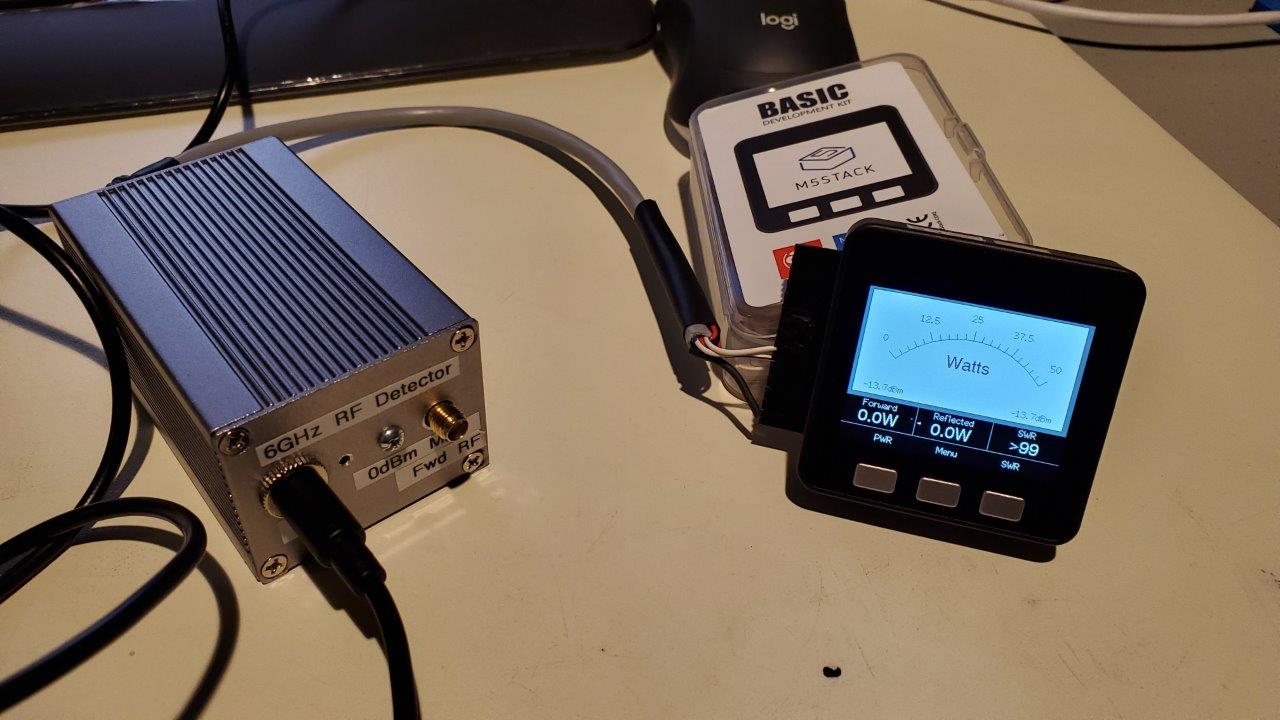
The result of my Version 1 effort is a small graphics display unit that receives input from a small box with dual detectors to measure forward and reflected power from a dual directional coupler of your choice to cover the frequencies of interest. I am only handling 1 coupler set at time today.
The M5Stack board manager package provides lots of sample code include an analog meter scale. So I coded up a SWR and Watt meter for microwave usage and is portable.
Here is the software main feature list:
1. Up to 6GHz (> 6 requires some more calibration or manual corrections)
2. Measures both forward and reverse power
3. Calculates SWR
4. Displays Watts and SWR on an analog meter face and digital values for Fwd, Ref, and SWR under the analog meter
5. Displays in multiple linear scales for watts. 1, 5, 10, 50, 100, 500, 1KW.
6. Displays dBm in the corners of the analog meter face.
7. Has hard coded Calibration sets to account for multiple couplers you own.
a. Easy to modify the code and upload when needed.
b. Hope to later make this field adjustable
c. Best used with dual directional couplers but still useful for single port.
d. Accounts for coupling factor for Fwd and Ref ports and adds extra fixed attenuator (added to both the coupling factors)
e. Have 5 sets defined currently, easy to add more
8. Could be made to work with many amplifiers built in dual directional couplers to add increased detail
9. Plan to write a PC side app to remotely read the wattmeter via WiFi and/or Bluetooth.
10. Set up the math to use 0dBm as full scale. That happens to be the AD8318's highest input for linear response. It is linear down to about -60dBm and up to 6GHz.
I obtained a couple of the AD8318 based Log Detector modules (now down to $7 each on Amazon) that I used in my LO box project that works up to 8GHz and build a sensor box powered by 12VDC. Inside the sensor box are the 2 detectors, a 7809 and 7805. The 9V steps down the 12 for less heat wasted, supplies 9V to the modules which use 7-12VDC, and 9V goes to the 5V regulator to minimize heat generated. The 5V supplies power to a USB Type C plug to power the M5Stack unit. This is for permanently installing. For short use the internal battery wll work, but still need 12V for the detectors.
To use:
1. Hook up the dual directional coupler to your sensor box, connect the sensor box to the IO ports on the M5 core, and optionally plug in USB for power or programming.
2. Edit the calibration set table data in the code to match your couplers and attenuator needs. You can create multiple cal sets to account for coupler factor differences vs frequency. Hope to make this easier down the road.
3. Push the menu button to bring up the Calibration Set screen. Hold the Menu button for > 1 sec to cycle thru the Cal Sets that are defined.
4. Push the left (Pwr) button to switch the Watt meter display. Push again to cycle through the scales
5. Push the SWR button to display the SWR scale. There is no other function on this button today.
The main thing to get right is choosing your total attenuation value to get the input of the sensor to be 0dBm (1mW) at full scale for the highest power you expect and that your coupler can handle. I have a range of 20 and 30dB couplers, some with cal tables on the front. I measured them all to be sure at the frequencies of interest. For 1KW and 30dB coupler, I use another 30dB fixed attenuator on both ports to handle 1KW (60dB total). Only need to handle 100W, than use 50dB total. As you cycle through the display scales, it will under range or overrange like a real analog meter would.
There is a fair amount of ADC conversion noise present so I had to do some data smoothing resulting in some averaging delays but still seems quite responsive. These are all values that can be tweaked. The ADC refence is internal 3.3VDC which looked stable on a multimeter. Don't have an o'scope here to look into it further. The sensor outputs have been clean in the past. Different Arduino boards may be less noisy. The Cypress PSoc5LP I used in the LO project is much cleaner.
I plan to install a 50Mhz to 1GHz dual coupler inline on my FL shack common feedline for 6 bands 50-1296 and use a WiFi connection to allow me to monitor power output on all bands when I am operating remote. Today I have no idea what is really going out the cable. An amp could be tripped offline for Hi SWR on 432 and I would not know other than a known station reporting they can barely hear me.
You can use other sensors but need to alter the math. The AD8318 uses an inverted output with max input = 0.5VDC and minimum around 2.3VDC. The AD8307 is linear from 0 to 2.5VDC and easier to program as a result but these are limited to 70cm band. I use one for a reflected power sensor for my 432 amp SWR shutdown input.
Code available on request. Will post it on my website later which is just only a basic template today. Need to get back on that project. Maybe even set up on Giithub someday.
Mike Lewis
K7MDL
CN88sf and EL87sm
I need an inexpensive SWR meter for microwave bands and in particular for remote monitoring. The small $50 Chinese mW meters work good, can talk to a PC via USB, and would take 2 of them per coupler so over $100 per coupler and requires a PC or hand calculator to figure SWR. I already worked out the AD8318 detector operation and they are only $6 each now so I envisioned a detector for every coupler port in use switched to a common cheap embedded CPU based meter. The detector input switching can be done by most CPU modules AD multiplexed inputs. The M5 core has 2 AD inputs predefined and brought out to the internal stacking connector and external IO headers. You can change other default pin assignments for more AD inputs.
The result of my Version 1 effort is a small graphics display unit that receives input from a small box with dual detectors to measure forward and reflected power from a dual directional coupler of your choice to cover the frequencies of interest. I am only handling 1 coupler set at time today.
The M5Stack board manager package provides lots of sample code include an analog meter scale. So I coded up a SWR and Watt meter for microwave usage and is portable.
Here is the software main feature list:
1. Up to 6GHz (> 6 requires some more calibration or manual corrections)
2. Measures both forward and reverse power
3. Calculates SWR
4. Displays Watts and SWR on an analog meter face and digital values for Fwd, Ref, and SWR under the analog meter
5. Displays in multiple linear scales for watts. 1, 5, 10, 50, 100, 500, 1KW.
6. Displays dBm in the corners of the analog meter face.
7. Has hard coded Calibration sets to account for multiple couplers you own.
a. Easy to modify the code and upload when needed.
b. Hope to later make this field adjustable
c. Best used with dual directional couplers but still useful for single port.
d. Accounts for coupling factor for Fwd and Ref ports and adds extra fixed attenuator (added to both the coupling factors)
e. Have 5 sets defined currently, easy to add more
8. Could be made to work with many amplifiers built in dual directional couplers to add increased detail
9. Plan to write a PC side app to remotely read the wattmeter via WiFi and/or Bluetooth.
10. Set up the math to use 0dBm as full scale. That happens to be the AD8318's highest input for linear response. It is linear down to about -60dBm and up to 6GHz.
I obtained a couple of the AD8318 based Log Detector modules (now down to $7 each on Amazon) that I used in my LO box project that works up to 8GHz and build a sensor box powered by 12VDC. Inside the sensor box are the 2 detectors, a 7809 and 7805. The 9V steps down the 12 for less heat wasted, supplies 9V to the modules which use 7-12VDC, and 9V goes to the 5V regulator to minimize heat generated. The 5V supplies power to a USB Type C plug to power the M5Stack unit. This is for permanently installing. For short use the internal battery wll work, but still need 12V for the detectors.
To use:
1. Hook up the dual directional coupler to your sensor box, connect the sensor box to the IO ports on the M5 core, and optionally plug in USB for power or programming.
2. Edit the calibration set table data in the code to match your couplers and attenuator needs. You can create multiple cal sets to account for coupler factor differences vs frequency. Hope to make this easier down the road.
3. Push the menu button to bring up the Calibration Set screen. Hold the Menu button for > 1 sec to cycle thru the Cal Sets that are defined.
4. Push the left (Pwr) button to switch the Watt meter display. Push again to cycle through the scales
5. Push the SWR button to display the SWR scale. There is no other function on this button today.
The main thing to get right is choosing your total attenuation value to get the input of the sensor to be 0dBm (1mW) at full scale for the highest power you expect and that your coupler can handle. I have a range of 20 and 30dB couplers, some with cal tables on the front. I measured them all to be sure at the frequencies of interest. For 1KW and 30dB coupler, I use another 30dB fixed attenuator on both ports to handle 1KW (60dB total). Only need to handle 100W, than use 50dB total. As you cycle through the display scales, it will under range or overrange like a real analog meter would.
There is a fair amount of ADC conversion noise present so I had to do some data smoothing resulting in some averaging delays but still seems quite responsive. These are all values that can be tweaked. The ADC refence is internal 3.3VDC which looked stable on a multimeter. Don't have an o'scope here to look into it further. The sensor outputs have been clean in the past. Different Arduino boards may be less noisy. The Cypress PSoc5LP I used in the LO project is much cleaner.
I plan to install a 50Mhz to 1GHz dual coupler inline on my FL shack common feedline for 6 bands 50-1296 and use a WiFi connection to allow me to monitor power output on all bands when I am operating remote. Today I have no idea what is really going out the cable. An amp could be tripped offline for Hi SWR on 432 and I would not know other than a known station reporting they can barely hear me.
You can use other sensors but need to alter the math. The AD8318 uses an inverted output with max input = 0.5VDC and minimum around 2.3VDC. The AD8307 is linear from 0 to 2.5VDC and easier to program as a result but these are limited to 70cm band. I use one for a reflected power sensor for my 432 amp SWR shutdown input.
Code available on request. Will post it on my website later which is just only a basic template today. Need to get back on that project. Maybe even set up on Giithub someday.
Mike Lewis
K7MDL
CN88sf and EL87sm

ba...@k7bwh.com
Mar 9, 2020, 11:13:00 AM3/9/20
to pnw...@googlegroups.com, k7...@hotmail.com
Mike, very nice job on your M5Stack. Thanks for the photos.
I just wanted to say thanks for mentioning the product. I wasn't aware of it and It looks really good. I've been developing a platform of similar capability and intent (based on Adafruit Feather M4 Express). I'll have to look much closer at the M5Stack. Maybe I don't need to make my own custom PCB and 3D printed case after all. :-)
Barry K7BWH
Seattle, WA CN87us
Reply all
Reply to author
Forward
0 new messages