NDVI/DVI and Orthos?

340 views
Skip to first unread message

Dan Murray

unread,
Jul 22, 2014, 7:02:57 PM7/22/14
to plots-i...@googlegroups.com
Hey guys,

Wanted to get a discussion started on NDVI/DVI processing from orthomosaics. I have been playing around with a couple solutions, and so far my favorite has been Agisoft Photoscan, however it seems it introduces some additional challenges. 

For one, I can't tell whether or not the ortho processing is doing anything to the resulting image that might interfere with the NDVI/DVI processing. On a few of my larger (50+ acre) mosaics, NDVI/DVI results show some very minor "splotching" in areas across the fields. I can't tell whether this is a legitimate trending in the vegetation, or a result of the way Photoscan is meshing the images together, possibly blending at different brightnesses. I have my camera (S100 with a red filter) set to manual mode, in this case with manual exposure at 1/1250 and ISO at 80. Take a look at this example:

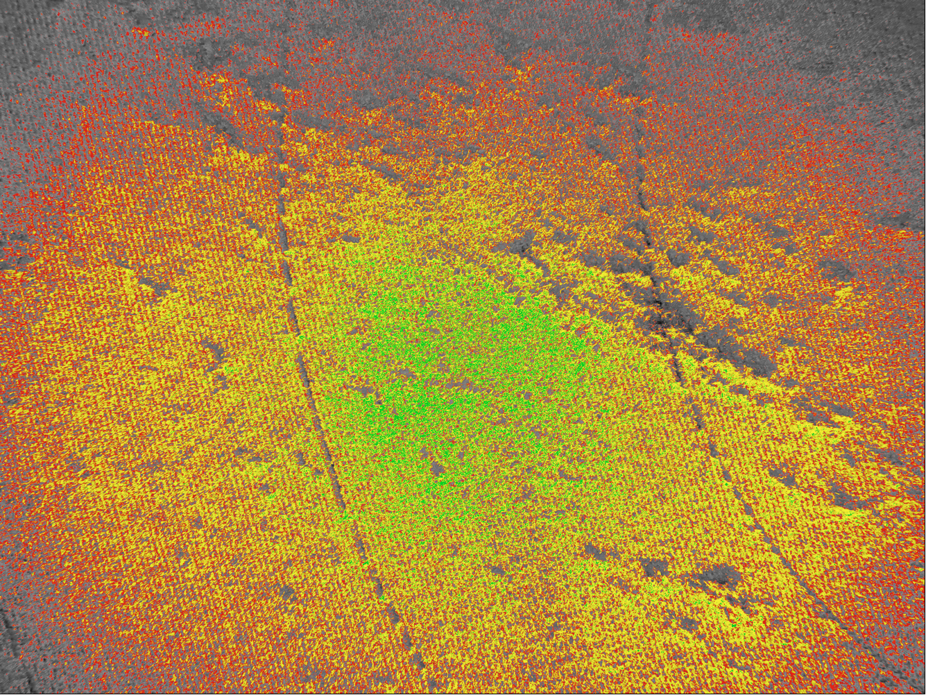
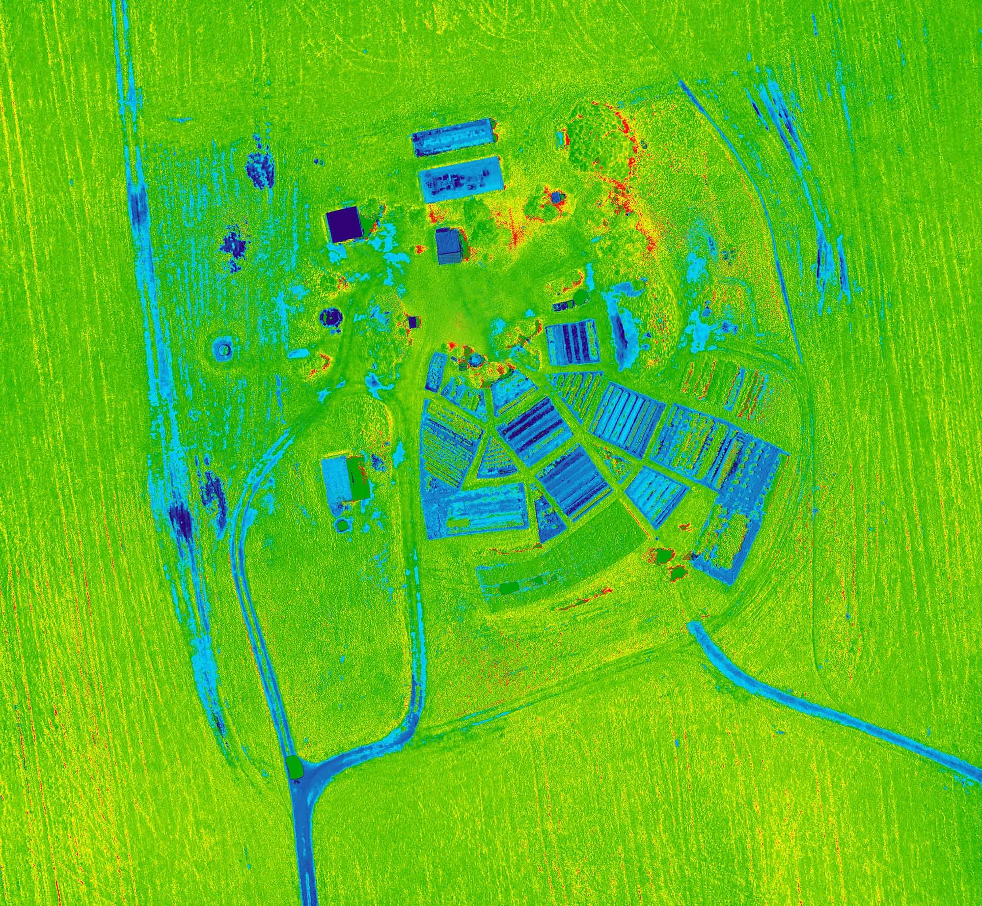
Additionally, the processing almost seems to suppress some of the variation between NIR and VIS. I have found that (in the case of DVI) reducing the scaling in Ned's plugin results in far more interesting results than simply using -255 and 255 (or -1 and 1 for NDVI). Without doing that, variances in the field are almost imperceptible. Is this something anyone else has experienced?

I would love to hear about everyone else's workflow, especially as to where the ortho-stitching comes into play, and how your results have been.

Dan

Ned Horning

unread,
Jul 23, 2014, 9:53:43 AM7/23/14
to plots-i...@googlegroups.com, Dan Murray
HI Dan,

My guess is that the artifacts that you are seeing in your mosaics are due to the way Photoscan is applying textures to the mosaic. You have a nice flat environment so the effects shouldn't be too pronounced unless you are flying very low or with a telephoto lens. When you make the mosaic in Photoscan you can choose the "Blending mode" and that will effect how the pixel values change. If you choose "Average" I expect you'd see reduced variation between pixels. If you chose "Min Intensity" or "Max Intensity" I expect the results would be more blotchy.

As for selecting different min and max scaling settings for the final product that is an excellent way to stretch the values as you found out. One way to determine a good stretch is to look at a histogram of an image output using min/max -255/255 or -1/1 and then set the min/max values to the value near the end of the tails of the histogram. I usually clip off a little bit of the tail since there are so few pixels there. One word of caution is that you need to record your min/max values for your or others to interpret the results. I suggest finding one or two settings that work well for a particular project and stick with those to avoid interpretation confusion. For NDVI a common min/max is 0/1 since most people don't care about negative NDVI values. For DVI you could use 0/1 I suppose. Anyway, use what works best for your application.

Ned
--
Post to this group at plots-i...@googlegroups.com
 
Public Lab mailing lists (http://publiclab.org/lists) are great for discussion, but to get attribution, open source your work, and make it easy for others to find and cite your contributions, please publish your work at http://publiclab.org
---
You received this message because you are subscribed to the Google Groups "plots-infrared" group.
To unsubscribe from this group and stop receiving emails from it, send an email to plots-infrare...@googlegroups.com.

Dan Murray

unread,
Jul 23, 2014, 12:00:22 PM7/23/14
to plots-i...@googlegroups.com, dmur...@gmail.com, Ned Horning
Thanks for the feedback, Ned. I tried "Average" and the results weren't appreciably different. I am starting to think the problem might be a side effect of some vignetting I noticed in the source images, especially in the NIR band:

That's pretty bad. I haven't been able to determine whether this is being caused by incorrect exposure/speed settings, or by the filter itself, but it's something I will need to experiment with some more. Have you run into anything like this before? These were taken at 1/1250 and ISO160, f4.5.

Thanks again,
Dan

Ned Horning

unread,
Jul 23, 2014, 2:49:08 PM7/23/14
to Dan Murray, plots-i...@googlegroups.com
Hi Dan,

That vignetting might be from the filter curling or something like that. That does look pretty bad. Are all your images like that? Do different camera setting change the effect?

Ned

Chris Fastie

unread,
Jul 24, 2014, 9:34:34 AM7/24/14
to plots-i...@googlegroups.com, dmur...@gmail.com, ne...@lightlink.com
What material is your red filter made from? Is it inside the camera or in front of the lens? I have not seen such strong vignetting in Powershots converted to IR. How did you make that color image showing the vignetting?

Dan Murray

unread,
Jul 24, 2014, 10:15:25 AM7/24/14
to Chris Fastie, plots-i...@googlegroups.com, Ned Horning
Thanks Ned. I am going to experiment with different settings, they don't all look like that. I think it may have been underexposed.

Chris, I am using Wratten 25a. The filter is inside the camera. For this picture, I simply did image subtraction of the blue channel (NIR) minus the red channel (VIS). I get similar results using Ned's photomonitoring plugin, using either DVI or NDVI. Again, not all pictures were this bad, only some. I thikn maybe ISO160 was too low for this. Would be interested to hear what exposure settings others are using for aerial shots...

Thanks!
Dan

Chris Fastie

unread,
Jul 24, 2014, 10:43:56 AM7/24/14
to plots-i...@googlegroups.com
Dan,
For kite flights with a super-red (Wratten 25A) Powershot I have used the lowest ISO (80) even on a cloudy day. The photos for this flight on a cloudy day were taken at ISO 80 and 1/640 second. Shutter priority mode allowed the aperture to be set for each shot, and it was always wide open (f/2.6), suggesting that there was not quite enough light for those settings. The photos were a little bit dim, but this did not result in vignetting.
Chris

Teddy Smyth

unread,
Jul 24, 2014, 2:58:47 PM7/24/14
to plots-i...@googlegroups.com
Hey Dan,

I'm working on a very similar workflow up at Middlebury College. I use a Wratten 25A filter in a Canon S100. I mosaic with Photoscan and process with Ned's plugin in FIJI, and so far I haven't had any major issues with vignetting. 

I've attached the blue (NIR) channel from one of my original images of the College's garden, as well as a quick mosaic and NDVI of the whole area.

Are you using a CHDK script to shoot, and if so, which? I use a slightly modified version of the KAP script and it meters every image and shoots at around 1/2000, f4.0, ISO~320. This has mostly been on sunny days. On an overcast (but not dark) day, I've shot at 1/2000, f2.0, ISO 400. This was ideal for minimizing shadows (which you can see have created some outliers in my NDVI). I'm prioritizing shutter speed to minimize blurriness, but I haven't noticed a substantial difference from bumping up the ISO. 

Best,
Teddy
garden_NDVI_compressed.jpg
gardenNIR_56_compressed.jpg
gardenNIR_mosaic_compressed.jpg

Dan Murray

unread,
Jul 25, 2014, 1:59:29 PM7/25/14
to plots-i...@googlegroups.com
Thanks Chris. I am thinking that at ISO80, 1/1250 was too short of an exposure. However, for UAV applications, I don't want to go too much lower, since obviously the UAV is moving during the collection process. I've only been doing this in manual mode though, so it sounds like I'd better start playing with the priority modes to see what works. Appreciate the input.

Dan


On Thursday, July 24, 2014 10:43:56 AM UTC-4, Chris Fastie wrote:

Dan Murray

unread,
Jul 25, 2014, 2:11:36 PM7/25/14
to plots-i...@googlegroups.com
Teddy,

Cool! So at least I know it can work reliably. I hadn't come across the KAP script; it looks significantly "smarter" than the simple intervalometer I have been using. I am going to dig into it. It is promising that you have had good results at 1/2000 with ISO400... I would much prefer quicker exposures; although most of my pictures are ok, sometimes the combination of speed and sudden banking slightly blurs otherwise good photos. 

Originally, I had thought that keeping the exposure values constant throughout the capture would be best for mosaic generation and in turn the NDVI processing, since there wouldn't be any variation due to exposure in the resulting image. I didn't base that on anything but my gut feeling - so perhaps I was off base. Have you run into any issues with the varying exposures? More so - have you run into any issues with PhotoScan itself blending the images? It looks like perhaps your mosaic is made up of only a few images (based on the size of the zoomed picture) - have you had good results with any larger datasets? Most of my surveys have been between 50 and 100 acres, with at least 500 images per run.

One last question for you - how have you been dealing with white balance? I have been using a red card to calibrate (since the infrablue guys are using blue cards), but have a hard time wrapping my head around the reason for doing this. My understanding is that white balance tweaks the gains on each channel - wouldn't it be best to have gains completely neutral for all three channels?

Teddy Smyth

unread,
Jul 25, 2014, 5:12:25 PM7/25/14
to plots-i...@googlegroups.com
Dan,

The KAP script is good, but it's a little slow (shoots a RAW image every 4 seconds). I might actually switch to a simple intervalometer because I'm worried about inconsistent NVDI measurements. On this run I didn't notice any NDVI problems, but it was my first attempt. The KAP script's ability to vary ISO etc. actually helped keep the images consistent this time, as the sun came out from behind the clouds halfway through the run. 

For the mosaic I sent, PhotoScan stitched together 100 photos with no big problems (with 15 disabled because of blurriness). These were taken at 70m over a total area of ~8 acres, and I surveyed 14 points with a total station. My largest run yet was 230 images over 28 acres, but I didn't try my NIR camera. Photoscan did well then too, with some distortion (as always) around the periphery. Your survey areas are much larger -- do you have to process in chunks?

For white balance, I've been using a sheet of paper printed red (255,0,0) held out under sunlight. Chris or Ned might have better tips -- I think they use a piece of red origami paper. I've also been planning to try using a red-emitting LED in a dark room. I'm not quite sure how white balance affects the channel gains. 

Best,
Teddy

Dan Murray

unread,
Jul 25, 2014, 5:56:24 PM7/25/14
to plots-i...@googlegroups.com
Teddy,

Guess I'll give the KAP script a try either way to see how it works out. 4 sec is probably too slow though, most of my runs are fast enough to require a max 3 second interval for proper overlap (I can bang out 75 acres in about 22 minutes!). But it's worth a shot.

I don't split into chunks, but I have the process running on a 16-core Xeon server with 4 GPUs (for the Dense Cloud)...the GPUs alone took the dense processing from about 12 hours to ~20 minutes or so. Actually, one thing I can't figure out is the mesh step. I have been building my mesh off the sparse cloud (not the dense), which makes the mesh building almost instantaneous, and the results (to my eye) look about as good as when I wait hours for the mesh with dense selected. I'm not sure what it's actually doing during this step, but I assume it works as well because the crops are (relatively) flat and as such don't need many points to look good.

That's what I've been doing as well, I just can't figure out why we use the red when white balancing. As I understand it, with a red piece of paper your measured R channel is much higher than your G and B (NIR) channels...assuming the paper isn't reflecting NIR. This seems like it would cause the camera to suppress the R gain. But I really don't know what I am talking about and would love to hear from the experts...I just can't wrap my head around it.

Dan

Ned Horning

unread,
Jul 25, 2014, 6:34:05 PM7/25/14
to plots-i...@googlegroups.com
Hi Dan,

I'm not an expert but I'll take a shot at explaining the red color balance. When you color balance the camera thinks you're using a color that reflects the same percent in red , green, and blue. In other works it thinks the card is gray or white. When you do a white balance with a red card the camera is effectively reducing the pixel values in the red channel and probably increasing the blue and green channels which likely results in bringing the red band values into a range that makes a nice looking image. The targets are, in perhaps, all cases reflect a good bit of NIR so that has to be taken into consideration as well since with a red filter a good bit of NIR light is detected by the blue (and green) detectors. It's helpful to remember that white balance doesn't actually change the sensor sensitivity but happen through an algorithm (I think before it's projected into RGB color space) in the camera so it doesn't effect RAW images.

Ned
--

Chris Fastie

unread,
Jul 25, 2014, 6:46:26 PM7/25/14
to plots-i...@googlegroups.com
I have not used that KAP script yet. It sounds like Teddy had a flight for which it made a difference because the lighting changed dramatically. If that does not happen, I assume we are better off keeping ISO constant so all photos have the same noise level. ISO might also affect color balance and contrast, so for many flights keeping it the same is probably best. I think you can set the parameters for that script so that ISO cannot change, and still take advantage of the intelligent shutter speed decisions. So if the light level drops and the aperture can't open any more, the shutter speed slows. However, there might be very few situations in which lowering the shutter speed is a good idea (maybe a kite or balloon flight when the wind is minimal). So my standard procedure of locking ISO and shutter speed and letting aperture vary may provide the best results in most situations. That does not require a script because if the Powershot does not have built in shutter priority, CHDK does. It does require making good decisions about ISO and shutter speed before each launch.

When using a single camera NDVI system like Infragram, if we want the photos to produce meaningful NDVI images without much post processing, the pixels representing foliage have to have the correct ratio of blue to red. That is (for super-red Wratten 25A cameras), the ratio of the value in the blue channel to the value in the red channel (blue:red or NIR:red) has to be between about 3:2 and 9:1. The standard white balance algorithms will not produce such ratios when the IR block filter has been replaced with a Wratten 25A filter. To nudge the camera into the right zone, we do a custom white balance while flooding the sensor with red light. That fools the camera into thinking that it needs to exaggerate the blue value for all pixels. If you use the right red color during the white balance procedure, the camera is fooled into adjusting the values for every foliage pixel so the ratio is in the right range, with blue (NIR) always higher than red. It's a complete kludge, but it works pretty well. The primary limitation is that you can't really compare NDVI values produced this way with NDVI values from other systems or even an identical system later in the day. The absolute values we get for NDVI are not calibrated in any way, they are just nudged into the general ball park where they belong. 

Dan Murray

unread,
Jul 25, 2014, 7:35:43 PM7/25/14
to plots-i...@googlegroups.com
Ned, Chris, thank you both. I hadn't considered that it was amplifying the blue channel. Is it safe to assume it is amplifying the green channel as well? I have noticed that the green channel is quite a bit more saturated than the red is in most of my images, and in the context of your explanations that would make perfect sense. Now that I know the "goldilocks" ratio range, I should be able to do some tests and see what balance paper works best for getting the right results.

I'm also interested in whether I can just use the RAW (CR2) images out of the camera and process them to fit the ratio prior to performing NDVI. It seems like that might be a better way to ensure consistent results. Has anyone tried that?

Thanks again,
Dan

Chris Fastie

unread,
Jul 26, 2014, 1:10:52 AM7/26/14
to plots-i...@googlegroups.com
Dan,

The Wratten 25A filter blocks almost all green light (in addition to blocking all blue light). So the light that ends up in the green channel is probably a mix of NIR, short red, and some long green. It will depend on the transmission of NIR by the green Bayer filter.  
.  

So it's hard to know why the green channel is the way it is in super-red Infragrams. It's hard enough to know what ends up in the red and blue channels.

Capturing RAW images is probably the best work flow. Even if you don't do the calibration procedure that Ned is working on, applying an adjustment to the RAW pixel values in the red and blue channels could result in appropriate ratios of blue:red for foliage pixels. If you are making ad hoc adjustments just to get the ratios you want, you can't do anything very scientific with the NDVI results. But if you have a reflectance target or two in the RAW image, then you can do Ned's calibration trick and produce actual data. This seems to be the workflow of choice to get the most meaningful NDVI results from consumer cameras.


Ned Horning

unread,
Jul 26, 2014, 8:47:12 AM7/26/14
to plots-i...@googlegroups.com, dmurray14@gmail.com >> Dan Murray
Dan,

Using RAW is a little more onerous but processing RAW images is easier in some ways since the sensor response is more or less linear so it reflects physical reality. Using JPEP mode all sorts of processing is made to create a pretty picture which in the long run degrades the data in make an image that is geared to perceived reality based on human vision. You should be able to use a bright and dark target (e.g., white printer paper and tar paper) with approximated reflectance values to get a reasonably good NDVI image. If you're interested in trying that I can work on a calibration plugin that you could use to calibrate RAW imagery. For each mission you would need to calculate new calibration coefficients but that shouldn't be too difficult.

Ned
--

Dan Murray

unread,
Jul 26, 2014, 2:49:20 PM7/26/14
to plots-i...@googlegroups.com, dmur...@gmail.com, ne...@lightlink.com
Thanks Ned. Sounds like I need to do some research on processing RAW files. I appreciate the offer for the plugin, but since my workflow involves processing a large survey, I think I will need to convert the RAW files to JPEG or TIFF for orthophoto generation prior to doing any NDVI/DVI analysis. So, it looks like I will need to find/develop a simple, standalone way to process the RAW photos into something else, taking into consideration the NIR/Vis ratio during this process. I don't have enough experience to know how easy this will be - looks like I need to do more reading.

My ultimate goal is to have the whole process, from original images to finished NDVI orthophoto generation, be completely automated. Still trying to wrap my head around the best way to do that, but as of right now it looks like it may be possible with Python scripting of PS, then some scripting in Fiji as well. Obviously the RAW component needs to come before all of this.

Thanks,
Dan

Ned Horning

unread,
Jul 27, 2014, 10:16:27 AM7/27/14
to Dan Murray, plots-i...@googlegroups.com
Dan,

Have you tried to use RAW images in PhotoScan. If you convert them to TIFF (a lossless format that will handle 2-byte integers) you should be able to keep the RAW values and import them into PhotoScan. If you go through the trouble of acquiring RAW images I'd avoid converting to JPEG if possible until perhaps the last step for presentation products. Converting from TIFF to JPEG is kinda like moving from science to art.

To automate the whole process I think you'll need to come up with a clever way to calibrate the images. One option is to use targets that you can automatically detect using feature detection algorithms and another, that would work if you are always taking images of similar types of landscapes, is to fit the histogram to match a histogram that you had calibrated (manually) in the past. Fitting the histogram could be as simple as doing a linear stretch based on image statistics of it could be more precise using a histogram matching algorithm.

The software you use could be guided by what you are most familiar/comfortable with. With the exception of the structure from motion work PhotoScan is doing I don't think the other steps are computationally intensive so ease of coding is probably an important factor in your decision.

Ned
Reply all
Reply to author
Forward
0 new messages