Nozzle and nozzle holders
3,789 views
Skip to first unread message

mojalovaa1
Feb 26, 2016, 9:14:12 PM2/26/16
to OpenPnP
Hi
I m open this post for discussion about nozzle and nozzle holder type , what is yours experience with nozzle .
My first nozzle is be like that is use Jason , I think that is Fuji CP6 nozzle , offset is disaster on rotation , not some good options but it is cheep .
Now I m buy Samsung CP45 neo nozzle and holder , difference type , very expense nozzle for that quality , my opinions is that not have good quality for that price (I m buy chines nozzle producer ) .
Some one have experience with that nozzle (CP45 neo ) ?
My old machine go max 300 mm /sec , and work with 0805 , 1206 , 5050 and bigger component , whom nozzle use for some dimension ?
Big problems make me if need place 1206 capacitors (1.2 or 1.6 mm thickness ) .
On my old machine for vacuum use compressor for cooler for make vacuum and vacuum is very high .
What is yours opinions for nozzle ?
Some one use Juki nozzle with rubber ?

Jason von Nieda
Feb 26, 2016, 11:13:57 PM2/26/16
to OpenPnP
I'm pretty interested in this topic myself. I'm running into serious runout with the shaft couplers I am using as nozzle adapters and was just today looking at options to make my own.
Due to these problems I may need to add nozzle runout compensation to OpenPnP before I can finish bottom vision.
Jason
--
You received this message because you are subscribed to the Google Groups "OpenPnP" group.
To unsubscribe from this group and stop receiving emails from it, send an email to openpnp+u...@googlegroups.com.
To post to this group, send email to ope...@googlegroups.com.
To view this discussion on the web visit https://groups.google.com/d/msgid/openpnp/5e70a3a7-0c92-4c8a-a413-1f53670cbf81%40googlegroups.com.
For more options, visit https://groups.google.com/d/optout.

mob...@gmail.com
Feb 27, 2016, 1:32:57 AM2/27/16
to OpenPnP
Serious pick and Place have good nozzle shaft with no runout and are made similar to drill spindles on Mill.
Then exists two other category. First have mechanical centering, second have optical feedback. Example is Cyberoptics laser centering. Lowest cost feedback is up looking video. Take snapshot , rotate, second snapshot and its possible to know runout.
If for example you check four quadrants and then do interpolation this should be enough and checking it is needed only once, so basically either you do it in hw, sw or combination.

Graeme Bridge
Feb 27, 2016, 3:13:02 AM2/27/16
to OpenPnP
Jason,
I have been looking at this adaptor and thinking that if one was made with a slightly smaller diameter than the shaft it could be heated and pressed onto the motor shaft. This would eliminate any need for seals or set screws which would create runout,. Alternatively a nice tight tolerance and hold it on the shaft with loctite bearing retainer
Jason von Nieda
Feb 27, 2016, 3:54:05 AM2/27/16
to OpenPnP
Graeme,
I believe the Robotdigg adapter that many people are using (and that I am waiting to receive) is a press fit on the motor side and a set screw on the nozzle side. People are reporting runout with these, but I am not sure at what point. One video I saw recently showed someone testing with an indicator but it was against the plastic ring which I think is a mistake. I'd suggest testing against the nozzle itself.
In any case, when I get mine I'll do said test and see what I come up with. Currently I am just using some cheap 5mm to 7mm shaft couplers off eBay and they are just too loose to be useful.
Jason
--
You received this message because you are subscribed to the Google Groups "OpenPnP" group.
To unsubscribe from this group and stop receiving emails from it, send an email to openpnp+u...@googlegroups.com.
To post to this group, send email to ope...@googlegroups.com.
To view this discussion on the web visit https://groups.google.com/d/msgid/openpnp/e1935045-a9d6-4f52-bea2-a45db38f46e2%40googlegroups.com.

Anthony Webb
Feb 27, 2016, 4:15:58 AM2/27/16
to ope...@googlegroups.com
I have 2 of the robotdigg adapters. I know one of them is darn near perfect, the other has some wobble. I will try and measure tomorrow just how much.
A lot of the wobble comes down to how you seat and tighten the nozzle into the adapter. There is a rubber gasket that can be compressed funny and cause it to seat a bit off.
I think it is wise to map the runout and offset for it where possible to give the optimal results.
Sent from my iPhone
Sent from my iPhone
To view this discussion on the web visit https://groups.google.com/d/msgid/openpnp/CA%2BQw0jy0KeGF%3D05tsTA_Ko%2BJECBFEv5MthAERv4YMJpaqFJ6aQ%40mail.gmail.com.

Cri S
Feb 27, 2016, 5:58:15 AM2/27/16
to OpenPnP
Before press fit to motor, runout of motor should be checked.
Graeme Bridge
Feb 27, 2016, 9:10:28 AM2/27/16
to OpenPnP
Agreed, i had thought this could be an issue but thought the robotdigg was a set screw fix to the shaft and that was the bigger issue.
To machine a bushing like this isn't technically difficult or even that expensive, My local shop would probably charge €3 on a batch of say 20-50 pieces
Anthony Webb
Feb 27, 2016, 4:05:55 PM2/27/16
to OpenPnP
Here are the results from both of my nozzles at the very tip.
RUNOUT at the tip:
Nozzle 1: .150mm
Nozzle 2: .038mm
On Saturday, February 27, 2016 at 2:15:58 AM UTC-7, Anthony Webb wrote:
I have 2 of the robotdigg adapters. I know one of them is darn near perfect, the other has some wobble. I will try and measure tomorrow just how much.A lot of the wobble comes down to how you seat and tighten the nozzle into the adapter. There is a rubber gasket that can be compressed funny and cause it to seat a bit off.I think it is wise to map the runout and offset for it where possible to give the optimal results.
Sent from my iPhone
Graeme,I believe the Robotdigg adapter that many people are using (and that I am waiting to receive) is a press fit on the motor side and a set screw on the nozzle side. People are reporting runout with these, but I am not sure at what point. One video I saw recently showed someone testing with an indicator but it was against the plastic ring which I think is a mistake. I'd suggest testing against the nozzle itself.In any case, when I get mine I'll do said test and see what I come up with. Currently I am just using some cheap 5mm to 7mm shaft couplers off eBay and they are just too loose to be useful.Jason
On Sat, Feb 27, 2016 at 12:13 AM 'Graeme Bridge' via OpenPnP <ope...@googlegroups.com> wrote:
Jason,I have been looking at this adaptor and thinking that if one was made with a slightly smaller diameter than the shaft it could be heated and pressed onto the motor shaft. This would eliminate any need for seals or set screws which would create runout,. Alternatively a nice tight tolerance and hold it on the shaft with loctite bearing retainer--
On Saturday, February 27, 2016 at 6:32:57 AM UTC, mob...@gmail.com wrote:Serious pick and Place have good nozzle shaft with no runout and are made similar to drill spindles on Mill.
Then exists two other category. First have mechanical centering, second have optical feedback. Example is Cyberoptics laser centering. Lowest cost feedback is up looking video. Take snapshot , rotate, second snapshot and its possible to know runout.
If for example you check four quadrants and then do interpolation this should be enough and checking it is needed only once, so basically either you do it in hw, sw or combination.
You received this message because you are subscribed to the Google Groups "OpenPnP" group.
To unsubscribe from this group and stop receiving emails from it, send an email to openpnp+unsubscribe@googlegroups.com.
To post to this group, send email to ope...@googlegroups.com.
To view this discussion on the web visit https://groups.google.com/d/msgid/openpnp/e1935045-a9d6-4f52-bea2-a45db38f46e2%40googlegroups.com.
For more options, visit https://groups.google.com/d/optout.
--
You received this message because you are subscribed to the Google Groups "OpenPnP" group.
To unsubscribe from this group and stop receiving emails from it, send an email to openpnp+unsubscribe@googlegroups.com.
Jason von Nieda
Feb 27, 2016, 4:07:23 PM2/27/16
to OpenPnP
Anthony,
Is this the Juki nozzles with the Robotdigg adapters? If so, could you run another test by swapping the nozzles? This will check if the runout is in the adapter or the nozzle.
Jason
On Sat, Feb 27, 2016 at 1:05 PM Anthony Webb <anthon...@gmail.com> wrote:
Here are the results from both of my nozzles at the very tip.RUNOUT at the tip:Nozzle 1: .150mmNozzle 2: .038mm
On Saturday, February 27, 2016 at 2:15:58 AM UTC-7, Anthony Webb wrote:
I have 2 of the robotdigg adapters. I know one of them is darn near perfect, the other has some wobble. I will try and measure tomorrow just how much.A lot of the wobble comes down to how you seat and tighten the nozzle into the adapter. There is a rubber gasket that can be compressed funny and cause it to seat a bit off.I think it is wise to map the runout and offset for it where possible to give the optimal results.
Sent from my iPhone
Graeme,I believe the Robotdigg adapter that many people are using (and that I am waiting to receive) is a press fit on the motor side and a set screw on the nozzle side. People are reporting runout with these, but I am not sure at what point. One video I saw recently showed someone testing with an indicator but it was against the plastic ring which I think is a mistake. I'd suggest testing against the nozzle itself.In any case, when I get mine I'll do said test and see what I come up with. Currently I am just using some cheap 5mm to 7mm shaft couplers off eBay and they are just too loose to be useful.Jason
On Sat, Feb 27, 2016 at 12:13 AM 'Graeme Bridge' via OpenPnP <ope...@googlegroups.com> wrote:
Jason,I have been looking at this adaptor and thinking that if one was made with a slightly smaller diameter than the shaft it could be heated and pressed onto the motor shaft. This would eliminate any need for seals or set screws which would create runout,. Alternatively a nice tight tolerance and hold it on the shaft with loctite bearing retainer--
On Saturday, February 27, 2016 at 6:32:57 AM UTC, mob...@gmail.com wrote:Serious pick and Place have good nozzle shaft with no runout and are made similar to drill spindles on Mill.
Then exists two other category. First have mechanical centering, second have optical feedback. Example is Cyberoptics laser centering. Lowest cost feedback is up looking video. Take snapshot , rotate, second snapshot and its possible to know runout.
If for example you check four quadrants and then do interpolation this should be enough and checking it is needed only once, so basically either you do it in hw, sw or combination.
You received this message because you are subscribed to the Google Groups "OpenPnP" group.
To unsubscribe from this group and stop receiving emails from it, send an email to openpnp+u...@googlegroups.com.
To post to this group, send email to ope...@googlegroups.com.
To view this discussion on the web visit https://groups.google.com/d/msgid/openpnp/e1935045-a9d6-4f52-bea2-a45db38f46e2%40googlegroups.com.
For more options, visit https://groups.google.com/d/optout.
--
You received this message because you are subscribed to the Google Groups "OpenPnP" group.
To unsubscribe from this group and stop receiving emails from it, send an email to openpnp+u...@googlegroups.com.
To post to this group, send email to ope...@googlegroups.com.
To view this discussion on the web visit https://groups.google.com/d/msgid/openpnp/CA%2BQw0jy0KeGF%3D05tsTA_Ko%2BJECBFEv5MthAERv4YMJpaqFJ6aQ%40mail.gmail.com.
For more options, visit https://groups.google.com/d/optout.
--
You received this message because you are subscribed to the Google Groups "OpenPnP" group.
To unsubscribe from this group and stop receiving emails from it, send an email to openpnp+u...@googlegroups.com.
To post to this group, send email to ope...@googlegroups.com.
To view this discussion on the web visit https://groups.google.com/d/msgid/openpnp/af0a0ea5-0d66-49c1-9068-2690e8f97e56%40googlegroups.com.
Anthony Webb
Feb 27, 2016, 4:42:03 PM2/27/16
to OpenPnP
OK After swapping both nozzles came back with exactly the same runout of .13mm.
It really does seem to me like you can effect the runout by how you tighten the 3 set screws on the coupler. There is a fair bit of play that the set screws are taking up.
I will note that I did also measure the runout at the end of the brass coupler as within .006mm basically perfect. So There is some combination of how they are attached or runout in the tip itself causing us grief.
Graeme Bridge
Feb 27, 2016, 4:59:31 PM2/27/16
to OpenPnP
Anthony
What is the internal diameter of the nozzle vs the adaptor shaft diameter? could a shim help centre the novel on the shaft reducing the amount of movement generated by tightening the set screws

Michael Anton
Feb 27, 2016, 5:08:48 PM2/27/16
to OpenPnP
I saw that video as well, and as the adapter was spun, it had significant visible runout on its own. By the time it gets further out to the nozzle, it would be even worse. I suspect in his case, that it was either a really bad adapter, or it didn't fit on the motor shaft properly.
Has anyone tried one of the Juki nozzle adapters that can be used for automated nozzle changing, like this one: http://www.ebay.com/itm/272037096520?_trksid=p2060353.m1438.l2648&ssPageName=STRK%3AMEBIDX%3AIT?
Mike
mojalovaa1
Feb 27, 2016, 5:29:17 PM2/27/16
to OpenPnP
Michael , you use that holder and nozzle ?
Have some one experience with that nozzle with rubber ?
I use CP45 neo nozzle but that is disaster nozzle for that money , and if move fast component on job then move it on the nozzle , I think that will be better if use nozzle with rubber ?
Have some one experience with that nozzle with rubber ?
I use CP45 neo nozzle but that is disaster nozzle for that money , and if move fast component on job then move it on the nozzle , I think that will be better if use nozzle with rubber ?
Michael Anton
Feb 27, 2016, 10:18:17 PM2/27/16
to OpenPnP
No, I don't have one, which is why I was asking. That is the holder I would like to use.
Typically rubber is only used on nozzles which are larger, or at least on the professional machine I use, that is how it is done. Perhaps your vacuum is not strong enough, and that is why the parts are slipping.
Mike

mikeselectricstuff
Mar 3, 2016, 8:12:15 PM3/3/16
to OpenPnP
Here's how the nozzles on my Versatronics work :
The head is a cylinder (approx 10mm dia) with two O-rings. The nozzle is plastic, with an internal brass ring which is a snug push-fit onto the head (an occasional smear of silicone grease on the O rings is helpful).
The nozzles have a flange, with a flat on either side.
The tool block has circular cavities, and a reraining plate on either side at the top. The cavities are lightly spring loaded so the flange of the tool rests on the underside of the plate.
The head also has a Z-axis sensor, which operates on an upwards force on the head ( it is sprung down), used to detect failure to load a nozzle
To load a tool the sequence is :
Move Y to adjacent top surface of tool block, push head down to check that a nozzle is not already loaded.
Head down into nozzle, rotate 45 degrees CW so flats on flanges are parallel with retaining plates, allowing nozzle to be lifted.
Lift Z, move Y to adjacent top surface of tool block, push head fully into nozzle
To unload :
Nozzle down into block, rotate 45 deg CCW so flanges engage behind retaining plate, lift head out of nozzle.
Video : tool block : https://youtu.be/ZaqvEftw7aI?t=459
Nozzle load : https://youtu.be/ZaqvEftw7aI?t=613

Genie Kobayashi
Mar 11, 2016, 4:34:22 AM3/11/16
to OpenPnP
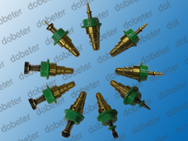
Hi, I have found Juki 500 series nozzle holder pics at Charmhigh Technology Limited web site with caption as follows...
Juki Nozzles, very easy opearation, magnet inside, no need to use wrench to pull down
http://www.smtpickandplacemachines.com/photo/smtpickandplacemachines/editor/20150507122559_59793.jp
It looks like made of brass. And, I'm going to try out laser 3D printing prototype of similar design with tiny ring magnet and P7 size fluororubber O-ring pushed inside.
Anyone already have this kind of magnetic nozzle holder for JUKI?
Anthony Webb
Mar 11, 2016, 8:33:07 AM3/11/16
to ope...@googlegroups.com
Those look a lot like the robotdigg couplers. Perhaps they modified them and inserted a ring magnet? At any rate if you do design something please share so we all can give it a try!
Sent from my iPhone
Sent from my iPhone
--
You received this message because you are subscribed to the Google Groups "OpenPnP" group.
To unsubscribe from this group and stop receiving emails from it, send an email to openpnp+u...@googlegroups.com.
To post to this group, send email to ope...@googlegroups.com.
To view this discussion on the web visit https://groups.google.com/d/msgid/openpnp/37849a0e-50b8-4090-b1ac-c76732b28bc8%40googlegroups.com.
Jason von Nieda
Mar 11, 2016, 1:02:47 PM3/11/16
to ope...@googlegroups.com
Nice find! These look like exactly what I've been looking for. I'm going to contact the manufacturer and see if they will sell them in small quantities.
Jason
--

Lisandro B
Mar 11, 2016, 1:42:07 PM3/11/16
to OpenPnP
Good news! Please let us know how it goes
Anthony Webb
Mar 11, 2016, 1:56:04 PM3/11/16
to ope...@googlegroups.com
If you can get them let me know, if not, lets design something similar! Tool changes may well be in our future!
-Anthony
To view this discussion on the web visit https://groups.google.com/d/msgid/openpnp/CA%2BQw0jxz_f6ScLss-HkSYKOb0f%3DbyYy68kbw9PWZxGjdhexBcQ%40mail.gmail.com.
Anthony Webb
Mar 11, 2016, 2:01:03 PM3/11/16
to ope...@googlegroups.com
The other bit I would consider buying if it is reasonable is the uplooking camera unless someone else has something similar in the works?
Jason von Nieda
Mar 11, 2016, 2:36:03 PM3/11/16
to ope...@googlegroups.com
I've got a 3D printed upward looking camera mount designed that I am pretty happy with. It encloses the ELP camera and has a mounting point for the same LED ring light I use on the top camera.
You can see it here: https://github.com/openpnp/openpnp-openbuilds/blob/develop/Mechanical/3D%20Printed/STL/Upward%20Looking%20Camera.stl
All the files for it are in the normal place in that repo.
I've not officially "released" this yet - that will come with the release of bottom vision, but it's a stable design I've been using for a couple weeks now.
One note on it, since it's not obvious from the drawings, but I was lazy and just hot glued the LED ring into the mount point. The LED ring mount part could be modified so that it snaps in instead, but as I said, I was lazy :)
Jason
To view this discussion on the web visit https://groups.google.com/d/msgid/openpnp/CALsNZy3SvdCg-RcnefkZUoVqboQ0nsPt--UtZEy3YC%3DfTGLUKQ%40mail.gmail.com.
Graeme Bridge
Mar 11, 2016, 2:45:10 PM3/11/16
to OpenPnP
Jason do you think it would benefit from the lens having a tapered flare out to the led ring, it would also stop things falling into the cavity
Jason von Nieda
Mar 11, 2016, 2:45:49 PM3/11/16
to ope...@googlegroups.com
Here's a picture of it in place that might help: https://imgur.com/a/MWCd6
Jason von Nieda
Mar 11, 2016, 2:47:02 PM3/11/16
to OpenPnP
Graeme,
Yep, I think that would be a good idea. Another option is just having a transparent film between the LED ring mount and the camera mount body. I originally designed this to use a 50x50mm polarizing filter film which served the same purpose but I decided against using it.
Jason
To view this discussion on the web visit https://groups.google.com/d/msgid/openpnp/b48aafaf-f747-43e7-af16-dea6c39decaf%40googlegroups.com.
Anthony Webb
Mar 11, 2016, 2:51:41 PM3/11/16
to ope...@googlegroups.com
Looks great! I'm gonna print one. Off hand do you recall the size of that light ring? Looks a little larger than the ones I got.
To view this discussion on the web visit https://groups.google.com/d/msgid/openpnp/CA%2BQw0jw5vwWsjCNtsx4YFPEPNhvw1v3Hw7COBXeneE2562fRzw%40mail.gmail.com.
Jason von Nieda
Mar 11, 2016, 2:53:44 PM3/11/16
to ope...@googlegroups.com
40mm OD
To view this discussion on the web visit https://groups.google.com/d/msgid/openpnp/CALsNZy2Z5mXyB34pWnEHaiBX9PomQq9eTsPK3NA0U8PKCjoVjQ%40mail.gmail.com.
Graeme Bridge
Mar 11, 2016, 2:58:20 PM3/11/16
to OpenPnP
Why did you change your mind on the filter Jason? I wonder if perhaps a fluorescent filter or one of the other SLR filters would be a good addition
Anthony Webb
Mar 11, 2016, 2:59:16 PM3/11/16
to ope...@googlegroups.com
Cool, same ones I have, and are you finding they have enough pizzazz to get the job done for upward looking camera? I've seen some crazy light arrays in both blue and red for those uplooking cameras and wasnt sure if there was benefit/need?
To view this discussion on the web visit https://groups.google.com/d/msgid/openpnp/CA%2BQw0jw8395EuGuchiG8%2BYLZEoekpBmQXJ0aChbBFu6Td9HG_A%40mail.gmail.com.
Jason von Nieda
Mar 11, 2016, 3:30:46 PM3/11/16
to ope...@googlegroups.com
Graeme: I was getting a lot of reflections off the filter and it was doing more harm than good. I think it may still end up being useful eventually, but I need to do more testing with it. It might also help if it was a glass one versus thin, cheap, plastic film.
Anthony: So far I am happy with the white LEDs although I think some kind of diffusion might help. I can't really say for sure yet if they get the job done for bottom vision because I am still struggling with other stuff related to bottom vision but not actually on bottom vision. Once I have some actual testable results I will definitely say more about it.
Here's a teaser of what I am currently working on, though. I'm very excited about this: http://grab.by/OKhe
User customizable computer vision pipelines are coming very soon!
Jason
To view this discussion on the web visit https://groups.google.com/d/msgid/openpnp/CALsNZy07czeT%2Bg8F0ay7pw8i_y00nJBC%3DFRRSQxxpLPVNasCKg%40mail.gmail.com.

Daniel Dumitru
Mar 12, 2016, 12:43:59 AM3/12/16
to ope...@googlegroups.com
Nice mount !
However ring-light has to be changed to a low angle ringlight. Otherwise you may have a lot of reflections generated (or to place in front a thick piece of milky plastic).
REgarding filters, maybe worth to try with a circular polarized filter from SLR world.
I was planning to print :
and to use
To view this discussion on the web visit https://groups.google.com/d/msgid/openpnp/CA%2BQw0jzX61fVCfE-jQLA3a2SD_PK1oQc9Hzp9KtC2OnTLL%3DYFA%40mail.gmail.com.
Jason von Nieda
Mar 12, 2016, 3:10:26 AM3/12/16
to ope...@googlegroups.com
Hi Daniel,
I haven't noticed any serious reflections with it - at least not so much that I think it will be a problem. While I agree that angled light might be better, I will note that many of the commercial machines I see use a flat light too, although I do notice many of them are square rather than round.
Do you have any thoughts on this? I'd be curious if you have experience with this and can explain the differences.
Thanks,
Jason
To view this discussion on the web visit https://groups.google.com/d/msgid/openpnp/CAPU3koNuT4aLOdp4cU%2BQGFjaT7QtjZ_R1WbSW0M3doMksLMczA%40mail.gmail.com.
Mike Harrison
Mar 12, 2016, 4:23:21 AM3/12/16
to ope...@googlegroups.com
On Sat, 12 Mar 2016 08:10:15 +0000, you wrote:
>Hi Daniel,
>
>I haven't noticed any serious reflections with it - at least not so much
>that I think it will be a problem. While I agree that angled light might be
>better, I will note that many of the commercial machines I see use a flat
>light too, although I do notice many of them are square rather than round.
This could be simply that it's easier to make flat PCBs - many of the ones I've seen are like a
>Hi Daniel,
>
>I haven't noticed any serious reflections with it - at least not so much
>that I think it will be a problem. While I agree that angled light might be
>better, I will note that many of the commercial machines I see use a flat
>light too, although I do notice many of them are square rather than round.
slice of an inside-out pyramid.
But another aspect is that most components are rectangular, so having light coming from 4 directions
is probaby going to give you more uniform edges to image than a circular source
DAniel Dumitru
Mar 12, 2016, 9:10:12 AM3/12/16
to ope...@googlegroups.com
Hello JAson,
All industrial machines that I have seen (on you tube) have low angle
lighting .
Indeed for uplooking camera reflections are not a problem since regular
components are small and are not glossy .
Like have wrote in tutorial a good example for lighting it's this page
from Cognex:
http://www.cognex.com/ExploreLearn/UsefulTools/LightingAdvisor/?langtype=1033
BR,
Daniel
On 12/03/2016 10:10 AM, Jason von Nieda wrote:
> Hi Daniel,
>
> I haven't noticed any serious reflections with it - at least not so
> much that I think it will be a problem. While I agree that angled
> light might be better, I will note that many of the commercial
> machines I see use a flat light too, although I do notice many of them
> are square rather than round.
>
> Do you have any thoughts on this? I'd be curious if you have
> experience with this and can explain the differences.
>
> Thanks,
> Jason
>
This email has been checked for viruses by Avast antivirus software.
https://www.avast.com/antivirus
Jason von Nieda
Mar 12, 2016, 1:04:23 PM3/12/16
to ope...@googlegroups.com
Thank you for posting that link Daniel, that is very informative!
I would definitely like to try an angled light and compare with my ring light.
Jason
--
You received this message because you are subscribed to the Google Groups "OpenPnP" group.
To unsubscribe from this group and stop receiving emails from it, send an email to openpnp+u...@googlegroups.com.
To post to this group, send email to ope...@googlegroups.com.
To view this discussion on the web visit https://groups.google.com/d/msgid/openpnp/56E4233F.8010003%40gmail.com.
Graeme Bridge
Mar 12, 2016, 2:03:35 PM3/12/16
to OpenPnP
Jason you could use some 90º light pipes in a printed ring to sit over the ring you have now

Rich Obermeyer
Mar 12, 2016, 2:40:05 PM3/12/16
to ope...@googlegroups.com
On FPD it came with a diffuser over the light ring that got rid of the shadows.
You might look at that again and place a similar one over your ring.
It beats building new hardware that may not work any better. :-)
It's an easy print to try different materials even.
To view this discussion on the web visit https://groups.google.com/d/msgid/openpnp/2516d27b-1332-4ead-b7d6-eef709f26ad4%40googlegroups.com.

alex
Mar 13, 2016, 5:12:38 AM3/13/16
to OpenPnP

I think it's possible to get nearly zero runout by making few more attempts but this is for sure not guaranteed way to get perfect repeatable result.
The next attempt will be nozzle holder made from bronze on lathe machine.
Anthony Webb
Mar 13, 2016, 5:40:04 AM3/13/16
to ope...@googlegroups.com
Hey alex, you should try a ring magnet in the mount to hold the nozzle, auto tool changing FTW!
--
You received this message because you are subscribed to the Google Groups "OpenPnP" group.
To unsubscribe from this group and stop receiving emails from it, send an email to openpnp+u...@googlegroups.com.
To post to this group, send email to ope...@googlegroups.com.
To view this discussion on the web visit https://groups.google.com/d/msgid/openpnp/2c2aef72-77b4-434d-b1cc-f78e4aba5a2f%40googlegroups.com.
alex
Mar 13, 2016, 7:45:08 AM3/13/16
to OpenPnP
Auto tool changing is too awsome feature to forget about it :)
But ring magnets of appropriate size are hard to find. So I was thinking about something like this:

The other question is sealing. I see two ways. First - just no sealing at all. Very accurate machining will give really small gap. In Juki nozzle there is no any sealing and it works well.
The second way is to use O-ring on Juki nozzle with OD just a bit larger than 7mm(OD of Juki nozzle itself).
воскресенье, 13 марта 2016 г., 12:40:04 UTC+3 пользователь Anthony Webb написал:
Genie Kobayashi
Mar 13, 2016, 2:30:45 PM3/13/16
to OpenPnP
Hi Alex,
What size of ring magnet is appropriate for your design? I have found Neodymium magnets of OD 5-6mm, ID 3mm, H 2-4mm, pulling force 300-600gf available, it would be located in the deepest part of the nozzle holder (opposite side of suction mouth).
http://www.magfine.co.jp/magnetjapan/user_data/neodymium_ring.php
I have researched China resources at eBay and Aliexpress then found one 6 x 3 x 3mm but pulling force around 200gf is a bit weak. I live in Japan, and I may be able to help you out to get an ideal one.
Cri S
Mar 13, 2016, 2:38:49 PM3/13/16
to ope...@googlegroups.com
I dont know the 2000 juky nozzle but the older series have all oring inside nozzle holder approx 5.5mm .
--
You received this message because you are subscribed to a topic in the Google Groups "OpenPnP" group.
To unsubscribe from this topic, visit https://groups.google.com/d/topic/openpnp/IG9cEUypjtM/unsubscribe.
To unsubscribe from this group and all its topics, send an email to openpnp+u...@googlegroups.com.
To post to this group, send email to ope...@googlegroups.com.
To view this discussion on the web visit https://groups.google.com/d/msgid/openpnp/bde0e5be-0077-459e-a5c7-f9bb470b2167%40googlegroups.com.
alex
Mar 13, 2016, 3:48:53 PM3/13/16
to OpenPnP
Hello Genie!
Thank you for your offer.
Hm, I was thinking about rign magnet located around nozzle with ID about 8-9mm. Locating ring magnet behind(above) nozzle is interesting idea. Ring magnets with 6-7mm OD are not rare and can
be easily found on aliexpress, etc. But there are two things that we shoud remember of:
1)I thing using really strong magnet is not good idea. Juki nozzle are made of magnetic material and strong magnet placed behind nozzle causes magnetic field on the tip of the nozzle wich may cause issues due to som magnetic smd parts.
2)Juki nozzle has a tube inside that moves by pressing on nozzle and returned by spring. This tube is long enough and when pressed the end of the tube extends on the other side of nozzle. so if magnet is located there this tube may stick to it.
Anyway I'll leave a place for both magnet locations.
воскресенье, 13 марта 2016 г., 21:30:45 UTC+3 пользователь Genie Kobayashi написал:
Cri S

Here is the photo of 506 Juki nozzle dissasembled. The is no o-ring inside for sure.
Jason von Nieda
Mar 13, 2016, 3:51:00 PM3/13/16
to OpenPnP
If you are in the US (or don't mind paying shipping) check out https://www.amazingmagnets.com/. I've bought many magnets from them and they have a huge selection, including a ton of different ring magnets.
Jason
--
You received this message because you are subscribed to the Google Groups "OpenPnP" group.
To unsubscribe from this group and stop receiving emails from it, send an email to openpnp+u...@googlegroups.com.
To post to this group, send email to ope...@googlegroups.com.
To view this discussion on the web visit https://groups.google.com/d/msgid/openpnp/de2390b8-33f7-4d0f-a117-6563be0b4077%40googlegroups.com.
Genie Kobayashi
Mar 14, 2016, 1:07:20 AM3/14/16
to OpenPnP
Hey Alex,
Yes, neodymium magnet has very strong pulling force and we should care about the part you noticed.
Thanks to Jason, I have found ID 9/32" (7.14375mm) ring magnets and it seems nice fitting at the bottom mating part of the nozzle holder but pulling force 9.19lbs (4.1685kg) is awfully strong for our purpose. And, if we can find one of pulling force 90% reduced, still I worry about collision with nozzle plug by magnetism when insertion. It should also happen with bar magnets, so we may require a stationary nozzle catch to remove plug head playing around.
Genie Kobayashi
Mar 14, 2016, 1:08:08 AM3/14/16
to OpenPnP
Hey Cri S,
I'm talking about JUKI 500 series nozzle and holder. Still given information from you is essential, I think P7 O-ring is required inside the holder. Thanks! :)
I'm talking about JUKI 500 series nozzle and holder. Still given information from you is essential, I think P7 O-ring is required inside the holder. Thanks! :)
Cri S
Mar 14, 2016, 5:48:29 AM3/14/16
to ope...@googlegroups.com
As I know there exist two old gold version and the new silver version of 500 Nozzles.
I'm attach images. The tb was for 500 series gold nozzles that is not displayed and is compatible with 100 series nozzles.
The silver version is used on ke2000 series
and above.
Il lunedì 14 marzo 2016, Genie Kobayashi <geniem...@gmail.com> ha scritto:
Hey Cri S,
I'm talking about JUKI 500 series nozzle and holder. Still given information from you is essential, I think P7 O-ring is required inside the holder. Thanks! :)
--
You received this message because you are subscribed to a topic in the Google Groups "OpenPnP" group.
To unsubscribe from this topic, visit https://groups.google.com/d/topic/openpnp/IG9cEUypjtM/unsubscribe.
To unsubscribe from this group and all its topics, send an email to openpnp+u...@googlegroups.com.
To post to this group, send email to ope...@googlegroups.com.
To view this discussion on the web visit https://groups.google.com/d/msgid/openpnp/b86a536e-769d-485b-b334-d73ca8f11f2b%40googlegroups.com.
Genie Kobayashi
Mar 14, 2016, 7:39:23 AM3/14/16
to OpenPnP
Thanks for heads up!
2016年3月14日月曜日 18時48分29秒 UTC+9 Cri S:
2016年3月14日月曜日 18時48分29秒 UTC+9 Cri S:
Genie Kobayashi
Mar 14, 2016, 8:08:07 AM3/14/16
to OpenPnP

2016年3月14日月曜日 4時48分53秒 UTC+9 alex:

Frank Herrmann
Mar 14, 2016, 10:10:59 AM3/14/16
to OpenPnP
I don't now if this a good idea to use magnets. The JUKI Nozzle is made of steel and also magnetic. I use some neodym magnets on my system, and at the end the resistor 0805 glue on this nozzle cuz she was magnetic. i decided, don't use magnets on a PNP system :)
Michael Anton
Mar 14, 2016, 6:33:01 PM3/14/16
to OpenPnP
Yes, many SMT components are magnetic. I can tell this is the case, as I have a waste cup on the SMT machine I run that uses a magnet to keep the cup in place. Many of the passive parts end up stuck to the magnet, usually most of the resistors, and capacitors. So, I agree that a magnet anywhere near a nozzle, would be a bad idea.
Mike

Bdale Garbee
Mar 14, 2016, 7:56:05 PM3/14/16
to OpenPnP
I looked at the Juki nozzles but wasn't impressed by the available mounting options. So, I thought I'd try something different.
I bought a set of replacement nozzles and the associated machine-side interface piece for a Samsung CP40 inexpensively through Aliexpress from seller Baifi Mall. The machine-side piece is a tube with a couple o-rings around it that presses into a nozzle. It has 5mm threads on the machine side, should be easy to make up an adapter on my lathe to interface that to a hollow-shaft stepper.
Then, I think it's going to be fairly easy to make a nozzle "stand" for the machine bed and program a "push down into the nozzle, then slide sideways to exit the holder" for picking up a nozzle and the reverse for putting one away. I'll post details once I get a little farther along with this...
If anyone else is
Bdale

SMdude
Mar 15, 2016, 2:31:47 AM3/15/16
to OpenPnP
I would have to agree against using a magnet to hold the nozzle in place. Have you ever used a pair of cheap tweezers(that have been near a magnet at some point in their life) for placing parts? There is nothing more frustrating!
Mick
Mick
Frank Herrmann
Mar 15, 2016, 4:44:55 AM3/15/16
to OpenPnP
Thanks for this tip, i order also this parts ... like it!
Daniel Dumitru
Mar 15, 2016, 6:03:41 AM3/15/16
to ope...@googlegroups.com
For good centering and smallest runout I don't think that a threaded rod it's best solution...
--
You received this message because you are subscribed to the Google Groups "OpenPnP" group.
To unsubscribe from this group and stop receiving emails from it, send an email to openpnp+u...@googlegroups.com.
To post to this group, send email to ope...@googlegroups.com.
To view this discussion on the web visit https://groups.google.com/d/msgid/openpnp/17749e0c-9fd7-4ecc-b466-84a492d547c1%40googlegroups.com.
Frank Herrmann
Mar 15, 2016, 8:01:34 AM3/15/16
to ope...@googlegroups.com
Sure, a runout are not a problem, cuz my software compensate a run out of nozzle. But with this cheap adapter and nozzles i'm more flexible. Also, the spring works in the holder and not in the nozzle. this makes the nozzles more cheaper. I give it a try :)
--
Frank Herrmann | Software Entwicklung+49 172 600 40 61 | xpi...@gmail.com
Neudorfer Weg.10 | 68753 Waghäusel
--
You received this message because you are subscribed to a topic in the Google Groups "OpenPnP" group.
To unsubscribe from this topic, visit https://groups.google.com/d/topic/openpnp/IG9cEUypjtM/unsubscribe.
To unsubscribe from this group and all its topics, send an email to openpnp+u...@googlegroups.com.
To post to this group, send email to ope...@googlegroups.com.
To view this discussion on the web visit https://groups.google.com/d/msgid/openpnp/CAPU3koM%3DKk9yd3wXUCp6qcwJAAJzRnO7WM6FindhMUY7YURiFQ%40mail.gmail.com.
Anthony Webb
Mar 15, 2016, 5:51:47 PM3/15/16
to OpenPnP
Mike is right, I thought that given the distance from the magnet and the tip, and the fact that the tip is plastic that it would not be a problem at all. But even with a smallish magnet there was still plenty of force to pick up a pretty big component. End result is we'll have to come up with a better alternative plan for auto tool changer.

Michael Anton
Mar 15, 2016, 6:39:21 PM3/15/16
to OpenPnP
You really would need an air puff to get the component off the end of the nozzle if using a magnet. :-) Gee, maybe we could eliminate the vacuum...
The brass nozzles that seem to exist, likely wouldn't have this problem, since brass is non-magnetic.
Mike
SMdude
Mar 15, 2016, 7:09:17 PM3/15/16
to OpenPnP
But with a brass nozzle, a magnet won't hold it in.
How do the commercial machines attach the nozzles when auto changing?
How do the commercial machines attach the nozzles when auto changing?
Mick
Jason von Nieda
Mar 15, 2016, 7:15:50 PM3/15/16
to OpenPnP
There are three strategies that I've seen used:
1. Friction: This includes the Samsung CP-40 nozzles where they use a couple o-rings and just slide the nozzle on over the o-rings.
2. Magnets: The Madell system uses a magnetic ring at the top that is bound to a brass coupler. You can see it here: http://www.ntscope.com/m2-2_parts.html
3. Interference: The Juki nozzles, and many others, have a physical holding system. The Juki nozzles, for instance, are designed to be held with a ball bearing coupler like you see on quick connect air systems. There's another one, Samsung CP-45 I think, that uses a weird angular block at the top. I have no idea what the adapter that holds it looks like.
Interestingly, it's been a while since I went to that Madell page and they have made some changes. For a while they showed some Juki nozzles with a "Coming Soon" thing. Now it looks like they are using parts of the Juki nozzles in their own nozzle adapter types, at the bottom of the page.
Jason
--
You received this message because you are subscribed to the Google Groups "OpenPnP" group.
To unsubscribe from this group and stop receiving emails from it, send an email to openpnp+u...@googlegroups.com.
To post to this group, send email to ope...@googlegroups.com.
To view this discussion on the web visit https://groups.google.com/d/msgid/openpnp/24983db2-a669-4b93-9405-028a2726a045%40googlegroups.com.
Mike Harrison
Mar 15, 2016, 7:28:02 PM3/15/16
to ope...@googlegroups.com
On Tue, 15 Mar 2016 23:15:38 +0000, you wrote:
>There are three strategies that I've seen used:
>
>1. Friction: This includes the Samsung CP-40 nozzles where they use a
>couple o-rings and just slide the nozzle on over the o-rings.
>2. Magnets: The Madell system uses a magnetic ring at the top that is bound
>to a brass coupler. You can see it here:
>http://www.ntscope.com/m2-2_parts.html
IMO magnets are a good idea as long as they are far enough from the part. They have the advantage
>There are three strategies that I've seen used:
>
>1. Friction: This includes the Samsung CP-40 nozzles where they use a
>couple o-rings and just slide the nozzle on over the o-rings.
>2. Magnets: The Madell system uses a magnetic ring at the top that is bound
>to a brass coupler. You can see it here:
>http://www.ntscope.com/m2-2_parts.html
that they will actively pull the nozzle into place so it seats in a consistent position, and by
controlling the magnet-to-metal distance you can adjust the pull-on distance and pull-off force.
My Versatronics uses friction & 2 o-rings, with a brass ring in the nozzle. This works OK, but does
mean the tool load cycle needs to include a push down to seat it, which may conflict with a 'light
touch ' or gravity-sprung z-axis design
It needs an occasional wipe of silicone grease on the o-rings.

Ray Kholodovsky
Mar 19, 2016, 1:05:53 PM3/19/16
to OpenPnP
I CAD'ed up and 3D printed the robotdigg style adapter a while back. Video here: https://plus.google.com/+RayKholodovsky/posts/XmUfxUyaPcK
It was a very very tight fit such that I had to press fit it onto the motor shaft using a vice. I couldn't get it straight enough to my liking but having read everyone else's dissatisfaction with the real machined ones, maybe mine was no worse.
I actually had to cut and saw the plastic off in order to remove it (I got the expensive tool changing holder as a replacement, it's not perfect but I'm much happier with the amount of runout it has).
Jason von Nieda
Mar 19, 2016, 1:07:21 PM3/19/16
to OpenPnP
I'm actually in the process right now of working with that company (top-cc) on a shorter version of the auto changing holder. We're going back and forth on design right now. I'll let the group know once we've settled on something and I will likely be buying enough to sell the extras.
Jason
--
You received this message because you are subscribed to the Google Groups "OpenPnP" group.
To unsubscribe from this group and stop receiving emails from it, send an email to openpnp+u...@googlegroups.com.
To post to this group, send email to ope...@googlegroups.com.
To view this discussion on the web visit https://groups.google.com/d/msgid/openpnp/57fca148-0e40-4e7d-bc94-2bfc7089ba8f%40googlegroups.com.
Anthony Webb
Mar 19, 2016, 1:22:06 PM3/19/16
to ope...@googlegroups.com
Jason,
On the shorter one will you double check the location of the set screw? The drawing had it at 5mm which might be kind of tight I think my nema 11 shaft is only 6.5mm long. My nema 8 shafts are already pressed on to the brass fittings so I cant check those. I'm thinking maybe 4 mm for the set screw might be safer.
Ray,
Do you have any videos of your new adapter? How long is it?
Sent from my iPhone
Sent from my iPhone
To view this discussion on the web visit https://groups.google.com/d/msgid/openpnp/CA%2BQw0jyKU6Mk1sVaw6eWCj3Rof0duu6zedB6iJzH0_ov4x2AaQ%40mail.gmail.com.
Ray Kholodovsky
Mar 19, 2016, 1:22:46 PM3/19/16
to OpenPnP
Jason,
Is the pricing working out favorably for you?
Having handled the part I can tell it's not as simple as I would have liked it to be, but was still thinking about reverse engineering it for either making on a cnc with 4th axis from round stock or getting a shop to make, but I'm really not sure what the cost would look like.
Jason von Nieda
Mar 19, 2016, 1:23:20 PM3/19/16
to ope...@googlegroups.com
Hey Anthony,
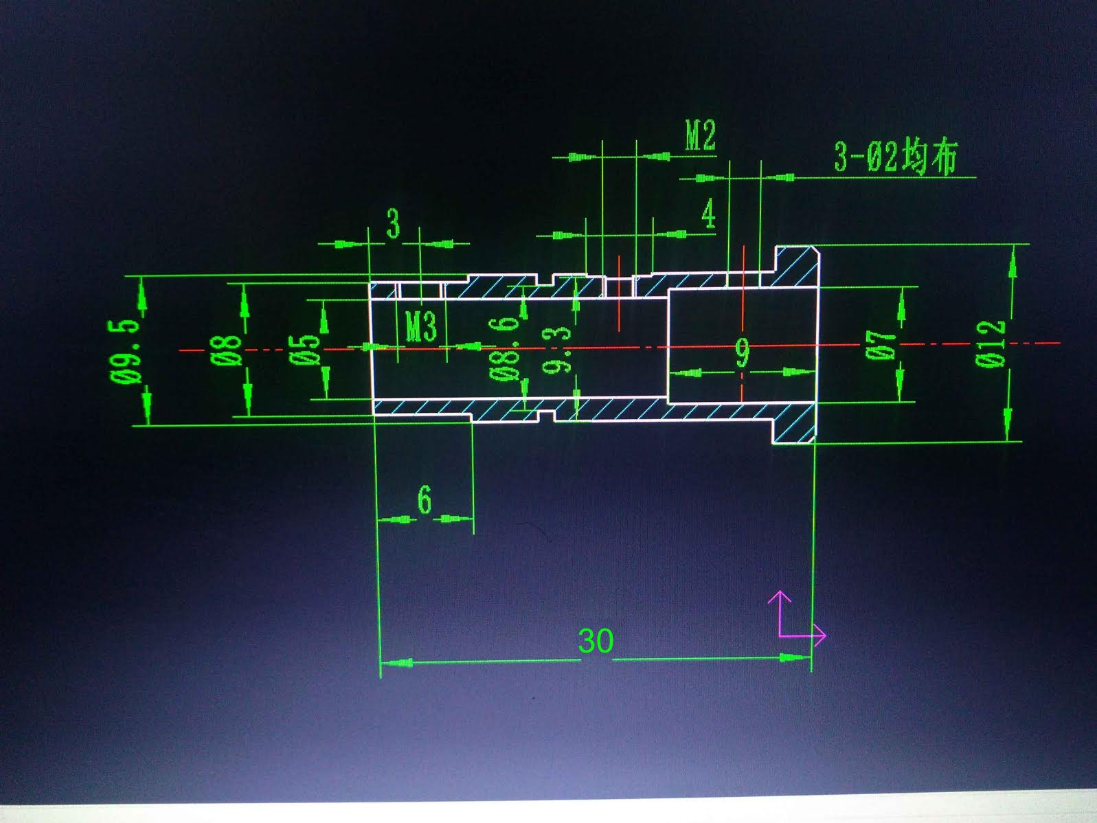
Yep, that is one of the things I had them change. Here is a drawing I just got back from them:
Jason
To view this discussion on the web visit https://groups.google.com/d/msgid/openpnp/EF17F5E3-B753-4105-8FB3-B36F1916F671%40gmail.com.
Jason von Nieda
Mar 19, 2016, 1:24:14 PM3/19/16
to ope...@googlegroups.com
Ray,
We've not discussed pricing yet. I'll definitely let you all know once I've got an idea on int.
Jason
Graeme Bridge
Mar 19, 2016, 1:46:51 PM3/19/16
to OpenPnP
That doesn't look that difficult to get machined, I know i could walk into my local engineering shop and get that produced with no issues. Why go to china? is there nobody in the USA that could make that at a sensible price?
Maybe I'm just lucky with my location as i can throw a rock and hit about 30 machine shops in a 5 mile radius
Ray Kholodovsky
Mar 19, 2016, 2:02:04 PM3/19/16
to OpenPnP
Jason,
Those dimensions work out nicely. Here is the original part for reference. My advice would be to have the undersize the 5mm opening for the motor by 0.02 - 0.03 mm. The 5.00mm spec is actually a bit loose. Undersize by .05 is robotdigg impossible to get on, use a vice. Undersize by .02 should be a nice snug fit. Btw the motor shaft from here: http://www.aliexpress.com/item/1pcs-nema8-8HY0001-7SK-hollow-shaft-stepper-motor-0-6A-30-mm-for-mill-cut-cnc/32518694080.html is actually 4.97mm OD, which is probably the reason for everything I just said. Don't have any robotdigg Nema8's to test on, so don't know how close they are to spec.
Graeme, it's just a bit more engineering work. We have the main piece which is pictured in Jason's message. Then we have (going in direction of motor to nozzle tip) a circlip ring holding a cylinder (like a 2.5mm thick washer) against which the spring pushes. There is a screw going through the cutout labeled 'M2', and finally there is the "sleeve" itself which slides up and down and allows 3 small detent balls to hold/ release the juki nozzle. So there's definitely some trial and error involved to get it all right. No idea what cost would look like.


Jason von Nieda
Mar 19, 2016, 2:03:38 PM3/19/16
to OpenPnP
Graeme,
Haven't you heard? America doesn't make anything anymore :)
Seriously though, I have had terrible luck trying to get anything like this made in the US. I think that is 90% of me not knowing how to go about it and 10% there not being many shops that want to deal with someone who only wants a handful of something. There's also the fact that I don't actually have one of these parts in hand, so I only know how it works and how it's designed from pictures. I couldn't actually produce a completely 3D drawing of it if I wanted to.
Jason
To view this discussion on the web visit https://groups.google.com/d/msgid/openpnp/50b55997-fdcf-4951-8756-fbb8e6ebb5a7%40googlegroups.com.
Graeme Bridge
Mar 19, 2016, 2:06:32 PM3/19/16
to OpenPnP
If you want a 3D drawing i can knock that out for you, infant any of us using fusion thats about 5 mins work.
Im also happy to get prices from the shops around me, I'm smack bang in the middle of motorsport central in the UK so people have the equipment to spit those out all day long
Material is brass or aluminium? or does it not matter?
Jason von Nieda
Mar 19, 2016, 2:07:11 PM3/19/16
to OpenPnP
Ray,
Thank you very much for sending these pictures. How do you feel about the quality of the parts? Are they within tolerance?
To your point, my NEMA 8 motors (all from Robotdigg) have 4.97mm shafts, so I will definitely get the hole undersized a bit. 0.05 is far too much, as you noted. The RobotDigg ones are a real pain to put on.
Jason
Graeme Bridge
Mar 19, 2016, 2:08:58 PM3/19/16
to OpenPnP
Your right sadly america doesn't, Im running my business split 50/50 with the UK and the USA but I've ended up with my manufacturing here in the UK because i know i can get things made easily.
I make China my very last point of getting things made as i honestly believe the only way the UK and US will ever dig themselves out of the mess we are in is to make things in our home countries.

Peter van der Walt (Gmail)
Mar 19, 2016, 2:09:39 PM3/19/16
to ope...@googlegroups.com
Wouldnt it work to add a flexture (like 3 vertical slots) to accomodate a variety of shaft precisions?
Peter
To view this discussion on the web visit https://groups.google.com/d/msgid/openpnp/CA%2BQw0jwK5%2B9WWyprfj%3DDouT80PO1ymaaMxxojE2mJ-NNgWEb7g%40mail.gmail.com.
Ray Kholodovsky
Mar 19, 2016, 3:02:58 PM3/19/16
to OpenPnP
Graeme - the one I have pictured is made from steel and anodized black.
Jason,
Ok, so go with 4.97mm ID and it should be a perfect fit.
I have mixed feelings about this whole thing. I don't have a gauge to measure it but there's still some runout. It's small and since I'm not designing anything smaller than 0603 at the moment I should be ok (yay reflow correction - surface tension), and hopefully any future 0402's will pan out nicely as well. I don't know if the runout is because of the 4.97 vs 5.00 disparity, but I feel like the Nema 8 shaft isn't long enough to correct. If the shaft was longer (the slot in the holder is full-through so it would accomodate no problem) I feel like we could rule that out because there's no way you could put it on crooked. Food for thought...
Back to the part itself, the up/ down slider is pretty good. After some actuations by hand I noticed that I can spin the juki. That's a red flag. What I will do is push the cylinder down a bit and this seats the nozzle more firmly. Now, the problem is that we can't move the cylinder lower because the sleeve pushes all the way up against it. So a stronger spring really is the only option.
So yeah, it's nice, and it's just complex enough that I understand the value of having it manufactured and assembled by a 3rd party that know what they are doing, but I don't believe the price should be as high as it is. $50 I would understand, although I would still want to find a way to get it down to $20-$30 (probably by trying to get it manufactured myself).


-Ray
Ray Kholodovsky
Mar 19, 2016, 3:04:05 PM3/19/16
to OpenPnP
Graeme - can you email me please. I have another drawing that may be of help. raykholo at gmail.
Ray Kholodovsky
Mar 19, 2016, 3:06:54 PM3/19/16
to OpenPnP
Peter if you are suggesting something like a stepped drill bit my concern is that the Nema 8 shaft is nowhere near long enough to accomodate that. And with a small holding surface length I would be even more concerned about maintaining concentricity .
I think we've settled on 4.97mm ID.
Jason von Nieda
Mar 19, 2016, 3:17:04 PM3/19/16
to ope...@googlegroups.com
Graeme,
Thanks for that! What I meant, though, is that until I received that technical drawing in my email this morning I had no real dimensions to go off of. Now I do, so I can produce a drawing and possibly have it made. That being said, I think I am going to add some tolerances to their drawing and ask them to make me one. I've come this far with them and I am willing to spend the money to just get something in my hand and go from there.
I would be very much interested if you (or anyone else) were able to get some quotes on a part like this. This is one of the pain points for DIY pick and place and has been for years now. I decided yesterday that I was sick of this being a pain point and so decided to see if I could do something about it. I figured that if I could get something made that would get the job done I would be willing to fund it and sell them in a web store or something just to solve the problem.
I'll keep you all updated as this process moves along!
Jason
To view this discussion on the web visit https://groups.google.com/d/msgid/openpnp/acb06f3a-ddbf-400b-aebe-ac6dfab895b6%40googlegroups.com.
Message has been deleted
Graeme Bridge
Mar 19, 2016, 3:28:58 PM3/19/16
to OpenPnP
lol my bad Jason
I will finish up the drawing if we want to change anything we can. I will also drop into my machine shop next week and get a quote as I'm going to see him anyways about some other parts.
What material are we thinking?
Ray's part is Steel with a chemi black coating by the looks of it. I know chemo black is expensive over here as i have my bolts done with that and you need to do a lot to get it cheap.
If its just a corrosion protection i would go with a zinc pas which will give a yellow/gold appearance
Im also happy to get prices on any parts you want, I spent 20 years building a supplier list of people who can make parts from packaging to machining and even high tech composites so to ping an email across is not a problem.
I have parts machined,laser cut, water jet cut,CNC bent powder coated and screen printed for my own product
Graeme
Jason von Nieda
Mar 19, 2016, 3:29:23 PM3/19/16
to OpenPnP
Graeme, you will probably know better than me on material. I feel like steel or brass would be good but I really don't have the experience to say. Aluminum might also work but I feel like aluminum is a little tougher to get a smooth fit with.
Jason
On Sat, Mar 19, 2016 at 12:25 PM 'Graeme Bridge' via OpenPnP <ope...@googlegroups.com> wrote:
lol my bad JasonI will finish up the drawing if we want to change anything we can. I will also drop into my machine shop next week and get a quote as I'm going to see him anyways about some other parts.What material are we thinking?Ray's part is Steel with a chemi black coating by the looks of it. I know chemo black is expensive over here as i have my bolts done with that and you need to do a lot to get it cheap.If its just a corrosion protection i would go with a zinc pas which will give a yellow/gold appearance
Graeme
To view this discussion on the web visit https://groups.google.com/d/msgid/openpnp/bdc07814-d205-490c-8aca-96fe51bb1a2a%40googlegroups.com.
Graeme Bridge
Mar 19, 2016, 3:33:40 PM3/19/16
to OpenPnP
I think i would probably go brass or aluminium Jason i know my guy can diamond turn so finish is really good, so much so that when you anodise the machining marks can actually be resolved away if they stay to long in the bath lol
Jason von Nieda
Mar 19, 2016, 3:53:46 PM3/19/16
to OpenPnP
Graeme,
My choice of the two would probably be brass, simply based on some minimal experience with brass versus aluminum shaft couplers. I defer to your experience though.
Jason
To view this discussion on the web visit https://groups.google.com/d/msgid/openpnp/46d6d764-8b37-4106-9bcf-21773b1638c9%40googlegroups.com.
Graeme Bridge
Mar 19, 2016, 4:00:51 PM3/19/16
to OpenPnP
I can get it quoted in all 3 steel,brass and aluminium.
Looking at Rays pictures there is a spring loaded ring, it looks like this is held in place with a circle. Im guessing this is the ball detent?
Jason von Nieda
Mar 19, 2016, 4:03:56 PM3/19/16
to OpenPnP
Graeme,
That's right, although someone who actually seen one of these things will have to explain how the balls stay in. As far as I can tell from the picture there are 3 balls in 2mm holes spaced 120 degrees apart. I'm not sure what keeps them from falling into the body though.
Jason
To view this discussion on the web visit https://groups.google.com/d/msgid/openpnp/19d776a3-bd26-4b11-9957-af7fec3129d8%40googlegroups.com.
Graeme Bridge
Mar 19, 2016, 4:14:38 PM3/19/16
to OpenPnP
Falling in in is easy its the falling out I'm interested in lol trying to decipher whats holding them in place
Jason von Nieda
Mar 19, 2016, 4:16:00 PM3/19/16
to OpenPnP
Well, we've got several people on this thread who own one of these or one quite like it. Would someone be willing to take a bunch of pictures and help us along? Ideally with the thing taken apart so we can see all the individual pieces?
Thanks,
Jason
To view this discussion on the web visit https://groups.google.com/d/msgid/openpnp/38a271c6-f110-497c-a650-fbb1f467f6e5%40googlegroups.com.
Ray Kholodovsky
Mar 19, 2016, 4:18:04 PM3/19/16
to OpenPnP
No no, there's actually 3 tiny little balls in the inside spaced 120 degrees apart that clamp it. An engineer friend of mine found me this nice pic of how the ball detent concept works:


Please see this video to understand the sleeve (lowest part) being depressed to perform the tool change. The cylinder I pictured earlier is static, I was making a different point with that. https://vimeo.com/144454866
Jason von Nieda
Mar 19, 2016, 4:20:03 PM3/19/16
to OpenPnP
Ray,
Understood, but what keeps the balls from falling in and/or out?
Jason
To view this discussion on the web visit https://groups.google.com/d/msgid/openpnp/d6c16a14-d3fc-4e1a-a927-b51c6c44c270%40googlegroups.com.
Graeme Bridge
Mar 19, 2016, 4:24:24 PM3/19/16
to OpenPnP
Falling in
The part has 2 holes for each ball, there is one the diameter of the ball say 2mm and then the one below that is 1.8mm so the ball can sit in the first hole and a section come through the second to act as the latch
Im curious whats holding them on the outside as there would typically be a spring on the back to keep constant pressure
Jason von Nieda
Mar 19, 2016, 4:25:50 PM3/19/16
to OpenPnP
Graeme,
The exterior slip ring keeps them from falling out, I believe. It slides over them and presumably has an indentation where they are allowed to come out of the holes a bit, with the straight part pushing them in fully when the ring is down.
Jason
To view this discussion on the web visit https://groups.google.com/d/msgid/openpnp/0c901d24-1214-418c-be2b-37dd54231694%40googlegroups.com.
Graeme Bridge
Mar 19, 2016, 4:28:40 PM3/19/16
to OpenPnP
so thats the small ring behind the circlip, hmmm thats not much holding the balls i would think you could push that past them and have them drop out
Ray Kholodovsky
Mar 19, 2016, 4:28:57 PM3/19/16
to OpenPnP
Right. I think the ball is sandwiched between the main part from the outside and the sleeve. That way the maximum diameter of the ball (from the half cross section view) is just slightly greater than the width of the slot it sticks through. And the sleeve then goes over this and prevents them from falling out. At least that's how I'd do it.
If you guys want to do a hangout on air in 1-2 hours I can take it apart based on instructions from you guys and it'll be a recording for future reference. Everything depends on getting the circlip ring out of that groove and off by moving it over the entire surface towards the motor which is where I left off my last attempt.
Jason von Nieda
Mar 19, 2016, 4:32:58 PM3/19/16
to OpenPnP
Hey Ray, that would be awesome! I've never participated in an "Hangout on Air" before, so if there is anything I need to do to make sure we get this recorded please let me know. In fact, please let me know if there is anything I need to do to prep or join. If you need to add me on G+ / Google Hangouts I'm ja...@vonnieda.org. I don't use G+ very much (at all) so I am kind of a newbie here.
Would you be able to nail down a specific time? I need to run out for a bit but I can adjust that based around when you are available.
Jason
To view this discussion on the web visit https://groups.google.com/d/msgid/openpnp/596adbe2-cbe4-493e-82f2-f3adb0498a5a%40googlegroups.com.
Graeme Bridge
Mar 19, 2016, 4:34:59 PM3/19/16
to OpenPnP
Ray the drawing you sent me is different to the part you have correct?
Graeme Bridge
Mar 19, 2016, 4:37:46 PM3/19/16
to OpenPnP
Here is a ball detent i designed for a spike to go on a speaker you can see there is a hole which is threaded M3, this let me put a small spring in after the ball and a set screw to adjust the pressure on the ball.
this design could be incorporated into the part if wanted as to would allow us to dial in how much grip the balls have on the nozzle
Ray Kholodovsky
Mar 19, 2016, 4:43:34 PM3/19/16
to OpenPnP
The drawing only shows the main part and omits the other "secondary components" such as the circlip, the 'thick washer', spring, balls, and the sleeve. The drawing I sent you shows my holder accurately though as far as dimensions though.
So can you join us on a video call in an hour or a bit more for the grand disassembly procedure?
...
It is loading more messages.
0 new messages