Re: Upconverter not working?
617 views
Skip to first unread message

Opendous Incorporated
Mar 8, 2014, 6:45:58 PM3/8/14
to open...@googlegroups.com
With the Upconverter powered up (USB plugged-in, LED next to USB
connector lit) and the switch in Upconvert mode you should see a signal
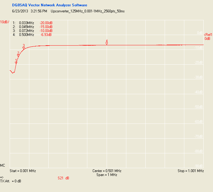
peak at 125MHz if you tune your RTL dongle to 125.1MHz or so with a 0.5MSPS sampling rate on the RTL dongle. This is
the natural LO bleed. It should disappear when the switch is in
Passthrough Mode.
If you do not see any such signal, that means the LO is not getting to the mixer (or the mixer is broken).
Please check with a multimeter the DC voltage across R2 (to right of the X1 oscillator can) when in Upconvert mode. It should read near 1V. This means the oscillator is fine and the problem is either in the LO filter or mixer.
If there is no voltage across R2, do you
happen to have any Half-DIP 4-pin oscillators around? If yes, please
try plugging one in and seeing if you get any DC voltage across R2 in
Upconvert mode. If yes, it means the original 125MHz oscillator is
broken.
> Tried inputting a 10 K Hz signal of 200mv into the front end
http://ifmaxp1.ifm.uni-hamburg.de/DBM.shtml
It is unlikely to get through in Passthrough mode as the Upconverter conversion losses dive below 50kHz.
If you are interested in pursuing the issue further, please contact me with any more readings and observations you make.
The easiest to source replacement oscillator is the DigiKey-stocked programmable SGR-8002DC which you can ask DigiKey to program for you:
http://www.digikey.com/product-detail/en/SGR-8002DC-SCB/SGR-8002DC-SCB-ND
Ariel Pimentel
May 2, 2014, 10:08:46 PM5/2/14
to open...@googlegroups.com
Hi,
I a few days a go i received the Ham it up v1.2 (125MHZ) upconverter. I plug it to the dongle ( switched 0t upconvert) an try to tune HF frequencies and nothing happend.
When i power up the upconverter an tune 125mhz i see a peak no matter if the switch in passthough or upconvert position, the peaks goes when is no power to the circuit.
''Please check with a multimeter the DC voltage across R2 (to right of the X1 oscillator can) when in Upconvert mode. It should read near 1V. This means the oscillator is fine and the problem is either in the LO filter or mixer''
Found cero voltage at R2 in upconvert mode.
I will appreciate your help.
Thanks
Ariel Pimentel
May 2, 2014, 10:30:24 PM5/2/14
to open...@googlegroups.com
El sábado, 8 de marzo de 2014 19:45:58 UTC-4, opendous escribió:
opendous
May 3, 2014, 7:01:11 PM5/3/14
to open...@googlegroups.com
> When i power up the upconverter an tune 125mhz i see a peak
> no matter if the switch in passthough or upconvert position
> no matter if the switch in passthough or upconvert position
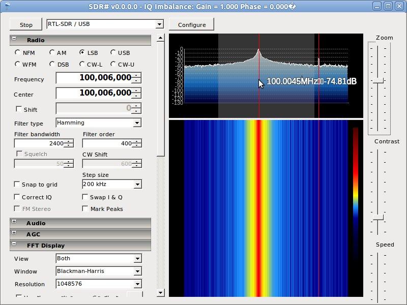
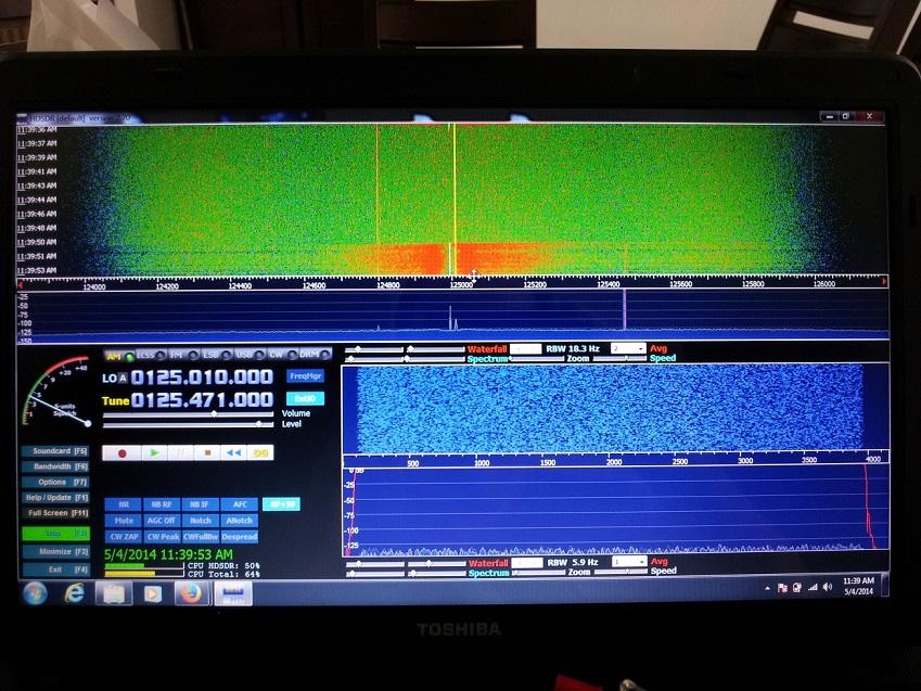
Please tune to 125.01MHz or so. Due to how I/Q demodulation works there will always be a peak at the center frequency. The LO bleed should appear near the tuned frequency at around 125MHz.
> Found zero voltage at R2 in upconvert mode.
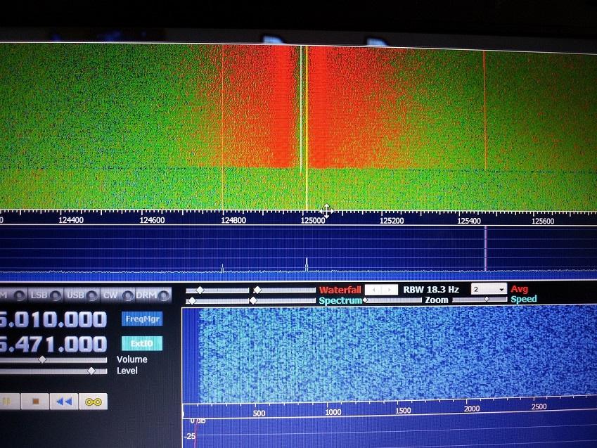
You also mention just one peak which means there is likely a problem. The LO is never exactly at 125MHz so it would not overlap the tuned frequency exactly.
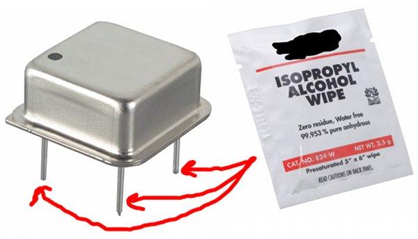
If the LED is on then power is available. Please try removing the oscillator and cleaning the contacts with alcohol. After the alcohol dries, please firmly press the oscillator into its socket. It sticks out a bit above the socket but the contact should be firm.
If you still do not get a second peak near 125MHz in your SDR software and there is zero voltage across R2, contact NooElec for a replacement.
> Found zero voltage at R2 in upconvert mode.
You also mention just one peak which means there is likely a problem. The LO is never exactly at 125MHz so it would not overlap the tuned frequency exactly.
If the LED is on then power is available. Please try removing the oscillator and cleaning the contacts with alcohol. After the alcohol dries, please firmly press the oscillator into its socket. It sticks out a bit above the socket but the contact should be firm.
If you still do not get a second peak near 125MHz in your SDR software and there is zero voltage across R2, contact NooElec for a replacement.
Ariel Pimentel
May 4, 2014, 12:29:24 PM5/4/14
to open...@googlegroups.com
Hi,
I cleaned the oscillator pins and see no voltage at R2.
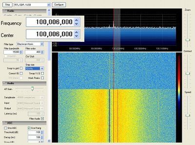
I do see the second peak (i forgot to mention in my first question,please see attached pictures.) The second peaks stay no mater the switch position, it only goes when power of the converter.
There is any voltage to measure at the witch pins in order to verify it working correctly ?
Is this a malfunction of the 4 pin Crystal oscillator ?
Thanks for your help.
Saludos
I cleaned the oscillator pins and see no voltage at R2.
I do see the second peak (i forgot to mention in my first question,please see attached pictures.) The second peaks stay no mater the switch position, it only goes when power of the converter.
There is any voltage to measure at the witch pins in order to verify it working correctly ?
Is this a malfunction of the 4 pin Crystal oscillator ?
Thanks for your help.
Saludos

phase2682
Aug 13, 2014, 9:22:17 PM8/13/14
to open...@googlegroups.com
I have the same failure mode as Ariel. May I get a replacement or is there a simple fix?
thanks for your assistance
Opendous Incorporated
Aug 16, 2014, 3:55:17 PM8/16/14
to phase2682, opendous
There are some simple checks that can be performed with a multimeter. The voltage between pin 1 (EN) and pin 4 (GND) of the oscillator should be 3.3V when in Upconvert mode (0V in Passthrough). Voltage between pin 4 (GND) and 5 (VCC) of the oscillator should be 3.3V. The voltage across R2 (next to the oscillator) should be about 1V (0.7V-1.3V depending on multimeter).
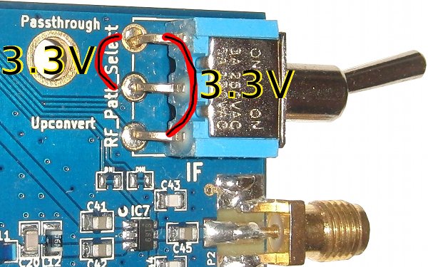
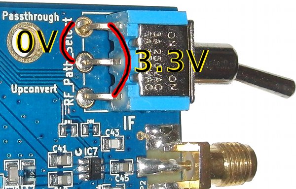
In Passthrough mode the voltage between the pin closest to the board edge and the other pins of the switch should be 3.3V. In Upconvert mode, the center pin of the switch should be 0V relative to the top pin.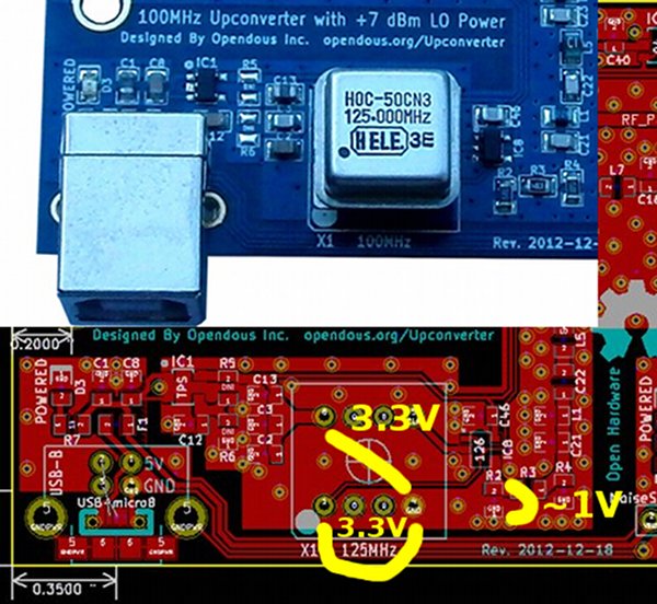
opendous
Aug 16, 2014, 3:56:50 PM8/16/14
to open...@googlegroups.com, phas...@gmail.com
The Upconvert to Passthrough switch in SDR software image shows 100MHz but that should read 125.06MHz.
Reply all
Reply to author
Forward
0 new messages