MMBTA92 & MMBTA42 anode switching circuit problem
656 views
Skip to first unread message

Tomasz Kowalczyk
Jan 17, 2018, 1:58:39 PM1/17/18
to neonixie-l


It is a fairly standard circuit. I've recalculated values to achieve lower current of the R25 resistor to limit dissipation on control elements.
The circuit is repeated 4 times for 4 tubes. These are multiplexed with a blanking period implemented. During blanking, cathode switches are still on (so only anodes are blanked). Multiplexing frequency is 250Hz (so operations happen every 1ms).
It generally works and switches the anodes, but... for some odd reason the PNP transistor (MMBTA92) decides to partially open whenever any other anode switch is open. I've checked the circuit with an oscilloscope and it seems that even with long blanking periods (over 0,5ms), the transistors will still falsely trigger. I've checked the bases and emitters and there is absolutely nothing, that could make the transistor open. I made few photos to describe the problem better:

Now it all looks like it is driven incorrectly and transistors are being open by the program. But it is not the case, here is the oscillograph taken from Q14 base:
As you can see, the signal at the base looks perfect! The signal appears only 1/4 of the time as supposed.
This effect of course causes ghosting, which usually is solved by implementing the dead time and not closing the cathodes during dead time. I've implemented both those methods and still I'm getting fooled by MMBTA92s!
The questions are:
Did anyone encounter similar problem with this circuit and/or these transistors?
Does anyone have any idea why do these transistors keep opening when they have no Vbe drop?
And why on earth anode voltage is kept low during blanking time, but then rises again without a base signal? It would make alot more sense if the transistor didn't close at all! But it closes as supposed and then reopens.
Tomasz Kowalczyk
Jan 17, 2018, 2:00:12 PM1/17/18
to neonixie-l
For some reason pasting photographs in google groups doesn't work as I would wish it to. So enjoy the two extra copies of photos at the top, which I didn't see, as I was trying to paste something at the point I was writing at that moment.

gregebert
Jan 17, 2018, 4:03:24 PM1/17/18
to neonixie-l
Can you check the signals on all 4 of the NPN bases at the same time? Neglecting blanking, they should look like 4 pulses, each 25% duty-cycle, with no overlap.
The 4th picture looks like this sequence:
- Anode 1 on
- Anode 1 & Anode 2 both on
- Anodes 1,2, and 3 on
- Anodes 1,2,3, and 4 on
The anode voltage progressively decreases, which looks like heavier loading on the power supply as more tubes are simultaneously on.
I checked the datasheets, and these transistors have plenty of margin, low-leakage, and decent switching speeds so no parasitic effects should be causing problems.
Tomasz Kowalczyk
Jan 17, 2018, 4:25:33 PM1/17/18
to neonixie-l
I'll be able to check it in few days.
Power supply won't be overloaded for sure, it's a 0-300V 1A lab power supply :)

Terry S
Jan 17, 2018, 6:12:52 PM1/17/18
to neonixie-l
I didn't look at your waveforms (or schematics), but if your switching speeds are very fast, this can cause transistors to turn on when they should not. The inter-element capacitance can pull the control element to the active state, even if it's not reflected on the pin itself.
Terry
Terry

sonixie
Jan 18, 2018, 4:09:42 AM1/18/18
to neonixie-l
Have you tried this anti-ghosting option? It works!
From my Penta (hence the "x5"): http://penta.xoom.it/
Cheers
Tomasz Kowalczyk
Jan 18, 2018, 4:52:16 AM1/18/18
to neonixie-l
Thanks, I'll try pulling to HV/2. I already tried pulling down to GND, but it didn't change much. It decreased the "discharge time" of incorrectly opened PNPs.

GastonP
Jan 18, 2018, 7:54:32 AM1/18/18
to neonixie-l
Hi Tomasz,
to me it looks like there is some kind of either capacitive coupling or leakage between the different drivers. You can see this from the different levels of the voltages at anode.
Besides what has been suggested to you, I would strongly advise to add a bleeder resistor between the base of the A42 (Q18) and ground. If the control voltage is 5V, then 2.2K would do.
Another option (just to help troubleshooting but involves no soldering) is to change the driving sequence to avoid adjacent tubes to be driven one after the other. For example if you are driving the tubes in 1-2-3-4 sequence, you can try with 1-3-2-4, which should produce ghosting only between tubes 2 and 3.
Hope this helps.
Gaston
Tomasz Kowalczyk
Jan 18, 2018, 1:15:36 PM1/18/18
to neonixie-l
I've checked the driving circuit before posting with oscilloscope and there is absolutely nothing incorrect visible up to MMBTA92s collectors. I've taken photos of the bases of PNP transistors - the signal is clean, as visible below:


There are only three channels shown, because I've actually shorted something while soldering pieces of wire to the bases, so one of the transistors ended up its life in a spectacular and loud way :) and I can't find the bag with more of these. So I desoldered it.
So, if there was a problem with capacitive coupling between wires leading to the board, some loose connections or capacitive coupling, it should be visible in here. All the bad stuff happens INSIDE of the MMBTA92s.
This is the signal at anodes of the tubes:

As you can see, there is no glitch while the channel with removed PNP transistor should be on, so it again narrows the problem to PNP transistor - if any other part of the circuit would be the one creating glitches, the glitch would happen at this time as well.
I've also added 10nF decoupling directly to HV input pins of my PCB, with no effect. Noise on HV rail is about 30mVpp and doesn't look like it is correlated with switching frequency.
I'm starting to think that I might have received a bad batch of transistors or they are just counterfeit - which would be sad news, because I consider the supplier (TME) as rather reliable.

Frank Bemelman
Jan 18, 2018, 1:29:02 PM1/18/18
to neoni...@googlegroups.com
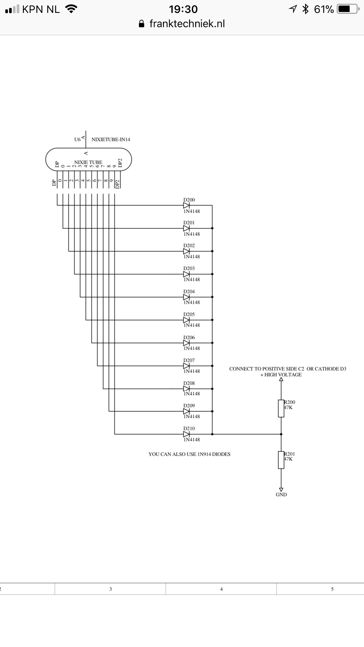
It is not the transistor that keeps conducting or leaking. The voltage you see at the anode comes from leakage from floating cathodes from the other tubes. What you can do to kill the ghosting is connecting 10 diodes to all tube cathodes. Connect the anodes of the 10 diodes to the 10 cathodes of the tubes. Tie all cathodes from these diodes together, and connect that to a voltage divider made of 2 resistors of 10k, between your 180v supply and ground. That should kill any ghosting...
Op do 18 jan. 2018 om 19:15 schreef Tomasz Kowalczyk <ten....@gmail.com>
--
You received this message because you are subscribed to the Google Groups "neonixie-l" group.
To unsubscribe from this group and stop receiving emails from it, send an email to neonixie-l+...@googlegroups.com.
To post to this group, send email to neoni...@googlegroups.com.
To view this discussion on the web, visit https://groups.google.com/d/msgid/neonixie-l/831d7192-f611-4b27-87c9-ac988c059ac4%40googlegroups.com.
For more options, visit https://groups.google.com/d/optout.
--
Vriendelijke groeten,
Frank Bemelman
Frank Techniek
Vennestraat 11X
2161LE Lisse
Telefoon +31 252 425 772
Frank Bemelman
Jan 18, 2018, 1:31:20 PM1/18/18
to neoni...@googlegroups.com

Dekatron42
Jan 19, 2018, 5:31:50 AM1/19/18
to neonixie-l
I can recommend reading the Burroughs document N101 on multiplexing Nixies which can be found here, if you haven't done so already: http://worldpowersystems.com/ARCHIVE/Burroughs/index.html .
/Martin
Tomasz Kowalczyk
Jan 19, 2018, 8:50:07 AM1/19/18
to neonixie-l
W dniu czwartek, 18 stycznia 2018 13:54:32 UTC+1 użytkownik GastonP napisał:
Another option (just to help troubleshooting but involves no soldering) is to change the driving sequence to avoid adjacent tubes to be driven one after the other. For example if you are driving the tubes in 1-2-3-4 sequence, you can try with 1-3-2-4, which should produce ghosting only between tubes 2 and 3.
I think that wouldn't solve the problem. This would just shift the ghosted digits to other tubes.
It is not the transistor that keeps conducting or leaking. The voltage you see at the anode comes from leakage from floating cathodes from the other tubes. What you can do to kill the ghosting is connecting 10 diodes to all tube cathodes. Connect the anodes of the 10 diodes to the 10 cathodes of the tubes. Tie all cathodes from these diodes together, and connect that to a voltage divider made of 2 resistors of 10k, between your 180v supply and ground. That should kill any ghosting...
I've tried this method, but with bigger resistors (power dissipation). Unfortunately, it didn't help. I had the pre-bias voltage at 120v with anode voltage 180V. Still I have ghosting present, it seems that it is not a cathode related problem - again narrowing to leaking PNP transistors.
W dniu piątek, 19 stycznia 2018 11:31:50 UTC+1 użytkownik Dekatron42 napisał:
I can recommend reading the Burroughs document N101 on multiplexing Nixies which can be found here, if you haven't done so already: http://worldpowersystems.com/ARCHIVE/Burroughs/index.html ./Martin
Thanks for the read. The driving method at figure 8 is clever, reducing the number of components on PCB. I think any microcontroller could be used in this configuration.
Tomasz Kowalczyk
Jan 19, 2018, 12:03:50 PM1/19/18
to neonixie-l
W dniu czwartek, 18 stycznia 2018 19:29:02 UTC+1 użytkownik Frank Bemelman napisał:
It is not the transistor that keeps conducting or leaking. The voltage you see at the anode comes from leakage from floating cathodes from the other tubes.
Oh it was just seconds ago when I understood what did you mean by the floating anode voltage. Right, that should happen, if one of cathodes is grounded, then literally any leakage current will cause 130Vish voltage on the anode to appear. However, this would mean that MMBTA92 have some serious leakage current issues if at Uce = 60V it leaks enough to cause visible glow.
However, that still makes me wonder why do they leak only when other tube is conducting. There is a cathode grounded at all times and there is no voltage drop across the tube when no tube is conducting (probe internal resistance causes the voltage to be not floating, that's why on the graphs it looks like it's about 0V during dead time).
Frank Bemelman
Jan 19, 2018, 12:52:56 PM1/19/18
to neoni...@googlegroups.com
Well, the voltage divider is at half of 180V, more or less 90V. Even is some current was leaking through your anode transistor, the voltage between tube anode and tube cathode, is still to low to cause any glow. The tube’s digit will only glow with a fully turned on anode transitor and cathode transistor. Give the diode patch a try and enjoy the result...
Op vr 19 jan. 2018 om 18:04 schreef Tomasz Kowalczyk <ten....@gmail.com>
--
You received this message because you are subscribed to the Google Groups "neonixie-l" group.
To unsubscribe from this group and stop receiving emails from it, send an email to neonixie-l+...@googlegroups.com.
To post to this group, send email to neoni...@googlegroups.com.
To view this discussion on the web, visit https://groups.google.com/d/msgid/neonixie-l/951afbbd-ff69-4fa9-8ca9-2106ee3b5bbb%40googlegroups.com.
For more options, visit https://groups.google.com/d/optout.

Jon
Jan 19, 2018, 1:01:52 PM1/19/18
to neonixie-l
Tomasz - which nixies are you using in this application? I seem to remember some discussion from years ago that some tubes (maybe ZM1000?) were particularly prone to ghosting and leakage effects even at microamp currents.
Jon.
Frank Bemelman
Jan 19, 2018, 1:02:23 PM1/19/18
to neoni...@googlegroups.com
And use a 50/50 divider, to make the voltage between anode and cathode of the tube as low as possible. Do not set it at 120V, but go for 90V, using equal resistors. If your HV is higher than 180V, try reducing that to at least 180V or perhaps 170V.
Op vr 19 jan. 2018 om 18:52 schreef Frank Bemelman <beme...@franktechniek.nl>
gregebert
Jan 19, 2018, 3:29:20 PM1/19/18
to neonixie-l
From the datasheet, collector leakage current is about 100nA. Assuming all of the NPN leakage current is amplified in the PNP, you would get 4-5uA of actual leakage to the anode from the PNP. That doesn't seem like enough current to me to cause a visible glow in a nixie.
Your scope probe (10meg) will "pull" 5uA of leakage current down to 50V. You can do a quick leakage test on the PNP by disconnecting the nixie anode, and any bleeder resistors, and measure the voltage at the PNP's collector when it's off (but while your power supply is on, of course). You should measure substantially less then 40v; anything near or more than that, confirms a leaky PNP or NPN. Be aware that if the NPN is leaky, it can cause a good PNP to appear leaky, because your driver is basically a 2-stage amplifier.
Based on the scope pictures so far, I'm not convinced it's leakage. But we need to know if we can rule it out.
The last set of scope photos show good turn-on, turn-off, blanking, and control signal behavior. So I think that can be ruled out.
There's definitely a clue with the 'ugly' shaped signals; I just havn't figured it out yet.
Can I assume your probes are properly compensated ? The leading-edge 'spike' at the anode when it turns on is hopefully the effect of the tube ionizing. But on the falling-edge I noticed some undershoot which goes significantly below 0 volts. That could be a clue.
Frank Bemelman
Jan 20, 2018, 8:42:42 AM1/20/18
to neoni...@googlegroups.com
Leakage in the NPN is of no concern. That gives a voltage across the 2k2 resistor of next to nothing, and won’t cause anything to wake up the PNP...
Op vr 19 jan. 2018 om 21:29 schreef gregebert <greg...@hotmail.com>
--
You received this message because you are subscribed to the Google Groups "neonixie-l" group.
To unsubscribe from this group and stop receiving emails from it, send an email to neonixie-l+...@googlegroups.com.
To post to this group, send email to neoni...@googlegroups.com.
To view this discussion on the web, visit https://groups.google.com/d/msgid/neonixie-l/8aac8a90-6197-4d1e-8963-f8b673a12842%40googlegroups.com.
For more options, visit https://groups.google.com/d/optout.
Tomasz Kowalczyk
Jan 20, 2018, 11:59:29 AM1/20/18
to neonixie-l
W dniu piątek, 19 stycznia 2018 19:01:52 UTC+1 użytkownik Jon napisał:
Tomasz - which nixies are you using in this application? I seem to remember some discussion from years ago that some tubes (maybe ZM1000?) were particularly prone to ghosting and leakage effects even at microamp currents.Jon.
B-5445
W dniu piątek, 19 stycznia 2018 19:02:23 UTC+1 użytkownik Frank Bemelman napisał:
And use a 50/50 divider, to make the voltage between anode and cathode of the tube as low as possible. Do not set it at 120V, but go for 90V, using equal resistors. If your HV is higher than 180V, try reducing that to at least 180V or perhaps 170V.
Actually I did use same value resistors, but the current from cathodes is big enough to make a difference. I used high valued resistors, though - 470k. I have only 0805 resistors and I don't want to fry them. I'll doodle around to get the real voltage at 90V and also check what will happen at 60V.
W dniu piątek, 19 stycznia 2018 21:29:20 UTC+1 użytkownik gregebert napisał:
From the datasheet, collector leakage current is about 100nA. Assuming all of the NPN leakage current is amplified in the PNP, you would get 4-5uA of actual leakage to the anode from the PNP. That doesn't seem like enough current to me to cause a visible glow in a nixie.Your scope probe (10meg) will "pull" 5uA of leakage current down to 50V. You can do a quick leakage test on the PNP by disconnecting the nixie anode, and any bleeder resistors, and measure the voltage at the PNP's collector when it's off (but while your power supply is on, of course). You should measure substantially less then 40v; anything near or more than that, confirms a leaky PNP or NPN. Be aware that if the NPN is leaky, it can cause a good PNP to appear leaky, because your driver is basically a 2-stage amplifier.Based on the scope pictures so far, I'm not convinced it's leakage. But we need to know if we can rule it out.The last set of scope photos show good turn-on, turn-off, blanking, and control signal behavior. So I think that can be ruled out.There's definitely a clue with the 'ugly' shaped signals; I just havn't figured it out yet.Can I assume your probes are properly compensated ? The leading-edge 'spike' at the anode when it turns on is hopefully the effect of the tube ionizing. But on the falling-edge I noticed some undershoot which goes significantly below 0 volts. That could be a clue.
I think that NPN transistors are not leaking at all, at least not significantly. PNP transistors base signal looks really clean, and also if the root of the problem would be leakage, then the problem would be visible during blanking period. For sanity check I'll try to make a differential reading of a PNP base and HV rail to check if there is a significant difference between those two or not during nominal off time.
That again narrows my mind to MMBTA92 only. I have some of these purchased from Aliexpress, I've gotta use these instead and observe if I get same result.
I'll check the voltage at the anode with the tube disconnected. I'll have to be careful, the sockets are holding the tube really tight and I bet the glass is getting stressed during dismounting.
The probes were recently compensated, however I'll check them again just to be sure. I also see the strange undershoot. It might be just some stray/probe capacitance discharging.
The probes were recently compensated, however I'll check them again just to be sure. I also see the strange undershoot. It might be just some stray/probe capacitance discharging.
Dekatron42
Jan 20, 2018, 12:19:30 PM1/20/18
to neonixie-l
You can also read about multiplexing Nixies here: https://threeneurons.wordpress.com/nixie-power-supply/ starting with the text "Nothing Turns-ON Instantaneously"
/Martin
Dekatron42
Jan 21, 2018, 12:47:32 AM1/21/18
to neonixie-l
Another document on multiplexing can be found here: http://www.tube-tester.com/sites/nixie/dat_arch/ZM1200_valvo.pdf it shows how the Pandicon, the ZM1200 series of Nixies, designs should be made to get them to work properly. It shows a string of zeners in the power supply section that delivers the different voltages needed for the catching diodes on both anodes and cathodes. The ZM1200 also contains an extra shielding electrode which is necessary since all of its nicies are contained in the same envelope close to each other, that electrode is of course not present when you have separate nixies.
/Martin

Nick
Jan 21, 2018, 2:32:48 AM1/21/18
to neoni...@googlegroups.com
I've created a properly optimised and searchable PDF with the correct metadata from the JPGs below which can be found in the group library under Nixie Tube Data -> Application Notes.
A direct link is https://drive.google.com/open?id=1xC765xBVZGuaampIQOWhEyG5oeEfr9Bw
I would encourage folk who have any of these documents to let me know and I'll add them to the group library (I have access to Adobe Acrobat to create & optimise documents)
Cheers
Nick
Dekatron42
Jan 21, 2018, 10:04:18 AM1/21/18
to neonixie-l
Nice!
Can you share how you made the PDF?
/Martin
On Sunday, 21 January 2018 08:32:48 UTC+1, Nick wrote:
I've created a properly optimised and searchable PDF with the correct metadata from the JPGs below which can be found in the group library under Nixie Tube Data -> Application Notes.
Nick
Nick
Jan 21, 2018, 12:06:24 PM1/21/18
to neonixie-l
Sure - I have a copy of Adobe Acrobat DC and used that - it allows you to assemble images into a PDF, optimise them, OCR the result and to set the metadata.
Nick
Dekatron42
Jan 21, 2018, 12:52:21 PM1/21/18
to neonixie-l
Ok, I have Acrobat Pro but I never get the results that I want when I try to do the same procedure. What, and how, do you do in the last three steps "optimise them, OCR the result and to set the metadata.", maybe I am doing something wrong. the problem I stumble upon the most is that the OCR is full of errors and it would take forever to correct it.
/Martin
Nick
Jan 22, 2018, 12:30:53 AM1/22/18
to neonixie-l
Nothing special - I used Adobe Acrobat Pro DC (Version: 2018.009.20050) - selected Edit PDF then Enhance Scans, then from the Enhance dropdown, select Scanned Document. Then make sure All Pages and Recognize Text are selected, before pressing the Enhance button. The metadata is set directly by right-clicking and editing the Document Properties.
Nick.
gregebert
Jan 22, 2018, 6:56:25 PM1/22/18
to neonixie-l
There is 1 other thing that could be happening, and although it wont cause ghosting, it will add confusion from the measured waveforms: If the PNP driver turns-on momentarily, for a few usec, it will charge the parasitic capacitance (scope probe AND nixie tube). If the duration is short enough, the tube will not ionize so there is no path to discharge the parasitic capacitance. From the waveforms, you can see the voltage level is below the ionization voltage. You can see the classic RC-discharge characteristic from the waveshape.
I dont know how the drive-signals to the NPN pre-driver are generated, but if they come from a shift-register, rather than a parallel output register, it could explain what you are seeing on the scope (strange and unexpected anode voltage when it should be off). Decode-glitches are a reality in digital logic; whether or not they are a source of trouble depends upon how the surrounding logic is designed. In this case, I think they are a source of confusion, and not actual trouble.
As far as the ghosting is concerned, how much blanking time are you using ? I saw 1 mention of 100usec above. What happens when you use a much longer blanking time, say 1msec (which should be gross overkill) ?
Tomasz Kowalczyk
Jan 22, 2018, 7:49:59 PM1/22/18
to neonixie-l
Nick, Martin, thanks for the read!
I'm using direct connection to a STM32 for every anode and cathode, no shift-registers or other driver chips, just anode switches as above and simple 10k resistors + MMBTA42s for cathodes. I'm using direct port commands - clearing all anodes at once for blanking, then clearing whole port at once and setting an anode and a cathode within a short period. I might try reversing it to "set cathode and then anode".
I can see the RC discharge, too. It would make much sense if not the drops during blanking time - anodes are pulled pretty close to 0 during blanking, yet they get to higher voltage again later - and they conduct, as ghosting happens, not only as these waveforms, but also as visible glow of other digits.
Blanking time is about 160us on later photos. I tried going higher, but even with 400us I'm seeing visible ghosting. For 1ms I'd had to tweak the timer, which I surely will do.
I have one test in mind - I recall having a fully differential probe at work. I'm going to measure anode resistor voltage drop - it will tell me exactly when the tubes are leaking (and hopefully I'll be able to calculate the current flowing). But that has to wait for a week or two, unfortunately. I'll perform all the tests suggested by you (BTW big thanks to every single one of you for helping) and port tweaking mentioned above then.
Reply all
Reply to author
Forward
0 new messages