Skip to first unread message

Kma Jack
Feb 28, 2019, 3:39:04 PM2/28/19
to mitappinv...@googlegroups.com
Hi all,
I am trying to create an app to send JSON data that contains just 2 number (ie: 12 or 22 or 34 etc) but noit sure how to do that. As you can see in the photo below, I have tried quite a few things but somehow it's not working. That is to say, when I send the 2 numbers, I can see them on the LCD screen of the Wemos D1 but they do not appear on the webbrowser page of the ESP8266. All I see on the webpage is a "0" (zero) and the number oin the screen changes to ")" as well. If I type in "192.168.0.108/22" or any other number after the IP address in to the address bar of the browser, then I get that number in the browsers JSON list and is also on the LCD screen.
I am trying to create an app to send JSON data that contains just 2 number (ie: 12 or 22 or 34 etc) but noit sure how to do that. As you can see in the photo below, I have tried quite a few things but somehow it's not working. That is to say, when I send the 2 numbers, I can see them on the LCD screen of the Wemos D1 but they do not appear on the webbrowser page of the ESP8266. All I see on the webpage is a "0" (zero) and the number oin the screen changes to ")" as well. If I type in "192.168.0.108/22" or any other number after the IP address in to the address bar of the browser, then I get that number in the browsers JSON list and is also on the LCD screen.
I don't know if I am sending the JSON data correctly or not filtering it out on the ESSP8266 sketch but as I can see the number I send over via the app on the LCD screen and also in the Serial monitor I am assuming that I must be doing something right, well, half right.
I am including the sketch below as well, hope that's ok.
Can anyone help p lease?
TIA
<script src="https://pastebin.com/embed_js/Y8w53sVb"></script>
}

Chris Ward
Feb 28, 2019, 7:45:08 PM2/28/19
to MIT App Inventor Forum
Hello Kma
When you say "That is to say, when I send the 2 numbers," do you mean that you succeed in sending the numbers via your App Inventor App?
"12 or 22 or 34 etc" each of those is one number........
If you are only sending two numbers from the App, that data does not need to be in JSON format. In your Sketch loop, the data is going to be read until '\r' is encountered, so your App should send the numbers as a text string terminated with '\r', your Sketch Loop is correctly defining the received text as JSON (ref: https://www.json.org)
From your blocks, it seems you have User input of the numbers in a TextBox? That's fine, just concatenate that with '\r' on the end using App Inventor's Text join block.
We need to see your schematic of the hardware setup. Your Sketch Code appears to be expecting the data to arrive via WiFi, assemble that into a JSON string and display that data in a browser?
Kma Jack
Mar 1, 2019, 7:32:29 AM3/1/19
to MIT App Inventor Forum
Hi Chris, thanks for your reply.
Sorry, did forget to mention that the numbers are sent via WiFi.
The D1 sketch loop seems to be receiving the data as it shows it on the LCD screen and in the Serial Monitor of the Arduino IDE. It also stores this value in the EEPROM. The problem is that it doesn't add it to the D1's webserver page (which will be a JSON list format). I thought the reason was because I wasn't sending it properly as a JSON via the App Inventor App.
I have added the "\r" block below the "testbox1-text" block but that hasn't made any difference either.
At the moment, I only have the D1 Mini and an LCD screen attached to it so there isn't a schematic as such, just the photo below.
In the other photo, it shows the first and last numbers I sent to the D1. The 66 is the new number and the 12 is the previous number sent that is being read out of the EEPROM.
NEW = new number sent
OLD = previous number stored in the EEPROM
EEPROM = is the new number written to EEPROM. That means that if I reboot the D1 the "OLD" number will change to this new number.
The "NEW =" and the "EEPROM =" numbers change if I send a different number (ie: if I send 22, both the 66's will change to 22 and on rebooting D1, the "OLD = 12" will change to "OLD = 22"
These don't mean anything at the moment, I am just practicing and when/if I get it right, it will be used in another project to controll a heater in a reptile tank remotely. I need to be able to add the number to the D1 webserver's JSON list so I can download it to the App Inventor App and see it. But as you can see in the third photo, I only get a zero and not the number I sent and I don't know if the problem is with the App Inventor App or the D1's sketch.
I have been able to filter out the number in the D1 sketch but that only works for showing it on the LCD screen, it does not add it to the JSON list on webserver page.
Thanks
Eric
Sorry, did forget to mention that the numbers are sent via WiFi.
Yes, I can send the numbers via the App Inventor App
When I said "numbers" I meant a 2 digit number, sorry got myself confused yesterday.
The D1 sketch loop seems to be receiving the data as it shows it on the LCD screen and in the Serial Monitor of the Arduino IDE. It also stores this value in the EEPROM. The problem is that it doesn't add it to the D1's webserver page (which will be a JSON list format). I thought the reason was because I wasn't sending it properly as a JSON via the App Inventor App.
I have added the "\r" block below the "testbox1-text" block but that hasn't made any difference either.
At the moment, I only have the D1 Mini and an LCD screen attached to it so there isn't a schematic as such, just the photo below.
In the other photo, it shows the first and last numbers I sent to the D1. The 66 is the new number and the 12 is the previous number sent that is being read out of the EEPROM.
NEW = new number sent
OLD = previous number stored in the EEPROM
EEPROM = is the new number written to EEPROM. That means that if I reboot the D1 the "OLD" number will change to this new number.
The "NEW =" and the "EEPROM =" numbers change if I send a different number (ie: if I send 22, both the 66's will change to 22 and on rebooting D1, the "OLD = 12" will change to "OLD = 22"
These don't mean anything at the moment, I am just practicing and when/if I get it right, it will be used in another project to controll a heater in a reptile tank remotely. I need to be able to add the number to the D1 webserver's JSON list so I can download it to the App Inventor App and see it. But as you can see in the third photo, I only get a zero and not the number I sent and I don't know if the problem is with the App Inventor App or the D1's sketch.
I have been able to filter out the number in the D1 sketch but that only works for showing it on the LCD screen, it does not add it to the JSON list on webserver page.
Thanks
Eric

ABG
Mar 1, 2019, 9:12:29 AM3/1/19
to MIT App Inventor Forum
I see a mismatch between how you format your data in AI2 (JSON)
versus how you parse the data in the Arduino sketch:
You include the ArduinoJSON library header
but you don't use it to parse the incoming JSON text,
instead using a very fragile substring operation.
ABG
Kma Jack
Mar 1, 2019, 10:02:14 AM3/1/19
to MIT App Inventor Forum
Hi ABG, thanks for your reply.
After days of hair pulling, that was the only way I could find how to filter out the number I sent.
I'm not a programmer so don't know about parsing. I'll try and find some info on it and maybe be able to do it.
Do you by any chance have a link to a tutorial please?
Thanks
Eric
After days of hair pulling, that was the only way I could find how to filter out the number I sent.
I'm not a programmer so don't know about parsing. I'll try and find some info on it and maybe be able to do it.
Do you by any chance have a link to a tutorial please?
Thanks
Eric
Chris Ward
Mar 1, 2019, 10:29:25 AM3/1/19
to mitappinv...@googlegroups.com
Hi Kma
In addition to ABG's comments:
You refer to a third photo but you didn't provide it.
- What is the Web Page displayed on?
- Has the web page been preformatted to accept JSON input? Or is it simply replaced each time to display new data?
- I note ABG's comment about parsing JSON but your App does not necessarily need to send the data in JSON format, just the numbers as a string which is concatenated into JSON format by the Sketch code - which does look correct. There is of course a million or so gotchas to be ironed out and we do not know enough about your project to know if your approach is correct - hence my request for a hardware schematic. I think we also need to have a schematic of the process because assembling your snippets of information it sounds like the App needs to both send and receive data. Drawing schemes may sound like a pita but they are so valuable in understanding your own processes. The hardware scheme can be drawn in Fritzing, or both schemes can be drawn in the free version of Serif DrawPlus.
ABG
Mar 1, 2019, 11:03:41 AM3/1/19
to MIT App Inventor Forum
I advise following @Chris's advice and posting a block diagram of
all the pieces of your project (software and hardware) and
the data that flows from each piece to the next.
For just a single datum, JSON is overkill.
FAQ:
ABG
Kma Jack
Mar 1, 2019, 2:10:12 PM3/1/19
to mitappinv...@googlegroups.com
Hi guys, thanks for sticking with me and sorry for the mistakes I make. I did add the third photo but must have somehow deleted it by mistake, sorry.
I downloaded Fritzing but it's only for original Arduino boards. The Wemos D1 Mini and the 20x4 LCD are not in the parts list at all so couldn't use that to make a connections diagram. I don't know any other software that does include them either, can't find any. I used photoshop to draw it and hope it's ok. I appreciate it must be hard for you to understand it all without schematics etc but that is honestly the best I can do. I hope it's ok.
I am adding the original D1 sketch that is so far working but is missing the sending data part. I am practicing on the first sketch I posted im my OP so as not to mess the original one up.
It's not just that data I want to add to the JSON webserver, there weill be 2 temperature/humidity sensors as well that send data to the webserver that I can download and show in the App Inventor App. So far it works and I can see the DHT sensor values both in the webserver page and also on the APP Inventor App. I have to refresh the webserver page manually to update the sensor JSON data. I need to find a way of making it refresh automatically somehow but that is not critical so not worried about that at the moment.
The webpage is displayed on my FireFox web browser the way the D1 Mini sends it with "client.print" in the JSON part of the sketch, see photo.
So to sum it up:
I can send DHT22 temperature and humidity data from the D1 Mini to the screen and to the webserver and also to the App Inventor App.
I just can't send data (2 digit number) to the D1 Mini from the App Inventor App and add it to the existing JSON data on the webserver which means I can't read it back with the App Inventor App.
Thanks
Eric
D1 Mini Sketch
Chris Ward
Mar 1, 2019, 2:45:46 PM3/1/19
to MIT App Inventor Forum
Hi Kma
I'm still struggling with your concept - in particular, why would the App need to receive the data it sent?
By the way - you can add your own components to Fritzing - you use a png/jpg image from the manufacturer/supplier, and convert + edit that to SVG format (with Corel Draw for example), so that the pins will be "intelligent". Using photoshop or similar is fine for schematics.
Concerning mistakes, you are nowhere near to taking my crown, I can make more mistakes in an hour than anyone makes in a day..........
Before your last post, I was wondering if you should either try TCP (extension) with your D1, or alternatively Bluetooth with an Arduino + BT or similar - which is a bit easier to set up. However, since you can receive data sent to your App, you seem to be 'half-way there'. Can you post (all) your App Inventor blocks as an image?
https://www.professorcad.co.uk/appinventortips#TipsBlocks How to insert an image of your Blocks into your Forum Post. Created by App Inventor, the image produced is high quality and can be zoomed - much better than a simple screenshot.
Kma Jack
Mar 1, 2019, 4:00:19 PM3/1/19
to MIT App Inventor Forum
Hi Chris, so I am not on my own than regarding mistakes, good to know LOL
The reason I want to send and receive data is really for 2 reasons. One is to learn and two is so that I can actually see what is stored in the D1's memory. If I can just manage to send the data and add it to the JSON list, downloading to the app is easy. I don't want the reptiles to die because of a mistake I made, my son won't be very happy with me LOL
In the meantime, I would really appreciate if someone can help me sort out the problem.
I've attached the sketch blocks photo for 2 sensors following your suggestion.
Thanks
Eric
The reason why I want to use WiFi is to be able to keep and eye on things while out of the house, can't do that with Bluetooth. Eventually, when (or if) I get it to work correctly then I aim to use a free DNS to keep in "touch" with the D1. I know I can use ThingSpeak but the idea is to learn. I am nearly 66 and need something to keep my brain functioning and make something I can use or give to my kids. This particular project I am working on is actually for my son who has 2 reptile tanks so he can keep an eye on the tanks when he is out of the house. Once everything is set up he probably won't need to change anything again but I want him to be able to turn the heaters and pumps on or off should something go wrong, even when away from home.
I also intent on (maybe) adding email notification if something does go wrong. That will save opening the App every now and then to check. From what I read and correct if I am wrong please, App Invertor Apps don't do push notification. I'll look in to that later though.
The reason I want to send and receive data is really for 2 reasons. One is to learn and two is so that I can actually see what is stored in the D1's memory. If I can just manage to send the data and add it to the JSON list, downloading to the app is easy. I don't want the reptiles to die because of a mistake I made, my son won't be very happy with me LOL
I wrote the sketch for an Arduino Uno and a Keypad LCD (16x2) to start with. It worked pretty good but the LCD uses a lot of pins and there were not enough left for the 4 relays plus an external ESP8266. I also had problems connecting the ESP2866 to the Uno, just don't know how TBH. I don't even know if the sketch is supposed to be uploaded to the Uno or to the ESP8266. I'll leave that for another time if I need it
I then changed to the D1 Mini and an I2C LCD screen (20x4), still don't have enough pins but at least it has WiFi so I can practice. I have ordered a NodeMCU that has more pins than the D1 and will use that when it arrives.
I only downloaded Fritzing yesterday and haven't had much time to play with it. I'll try and add components so that if I need help again I can make better connection diagrams. Thanks
I only downloaded Fritzing yesterday and haven't had much time to play with it. I'll try and add components so that if I need help again I can make better connection diagrams. Thanks
In the meantime, I would really appreciate if someone can help me sort out the problem.
I've attached the sketch blocks photo for 2 sensors following your suggestion.
Thanks
Eric
Chris Ward
Mar 1, 2019, 8:41:24 PM3/1/19
to MIT App Inventor Forum
Hi Kma
So, few things missing from your Scheme - Reptile Tanks, other sensor set, relay module, WiFi router and whatever hosts the web page :)
You can couple an extension board to an Arduino for more pin-outs. NodeMCU is a good choice though.
Notes:
App Inventor Apps don't do push notification They can't push in a useful way because Android Background Services are not supported. However, you can send an email and post a warning on the website via the microcontroller. You can also set a Schedule on the phone to run the App at specific time intervals.
Blocks: Right at the top of Web1.gotText, you are overwriting responseContent. Unsafe. You should define your own separate variable for that data.
Concerning the management of the App GUI, I have seen the button long click code touted elsewhere in a tutorial. It is however, very bad practice. The GUI should not have individual components like buttons (setup button, save button) apparently disappearing from the screen, and the fact that a long click is required is not obvious and thus not User friendly.
Web1 should only be called by one source. Button1 should enable the Clock Timer that calls Web1. The test inside that timer does not serve a useful purpose - if necessary, you could simply set the timer interval 5 times slower. Button1 should set Web1 URL to the global you have defined, and that's it - the Timer does not need to set it (if the timer sets it, the data stream is interrupted). Set the Timer duration etc in the Screen.Initialize Block. Once the connection has been established, the Timer should be disabled.
The ESP2866, the Phone Device and the App should all be addressing the router (i.e. all using the same WiFi network). The IP is usually hard-coded in the microcontroller Sketch and the App for one-off projects.
When the ESP2866 is attached to an Arduino, the Sketch is uploaded to the Arduino (or other microcontroller). The Arduino Uno WiFi board has a WiFi module built in.
Security is important - you don't want someone to be able to intrude and maliciously change the Tank settings.
Chris Ward
Mar 1, 2019, 9:00:03 PM3/1/19
to MIT App Inventor Forum
Hi again
The App is designed to report critical Tank environment data. It's worth considering the use of a Web Cam too, so that the reptiles can be seen to be OK.
Message has been deleted
Kma Jack
Mar 2, 2019, 10:05:11 AM3/2/19
to MIT App Inventor Forum
Hi Chris,
Sorry, didn't know I should add "Reptile Tanks," etc to the schematis. Can I ask why it's importat to add them?
I do have a pins extension board but the relay modules are not I2C compatible so it's not good for this project, as far as I know anyway.
re: the "Web1.gotText", I added that in a few days ago when I started experimenting sending data (numbers) to the ESP8266's webserver, sorry forgot to delete them
I am using the "long click" because using a short click could lead to hidden items appearing if the button is even touched slightly. It's just my son who is gonna use the app so it won't be a problem using it. I read somewhere that using more than one screen was a bad practice, hence my reason for using hide and show of the setup blocks.
re: "The test inside that timer does not serve a useful purpose", sorry buyt what "test"?
My idea was to create an app to show the temperature and humidity in (nearly) realtime. I don't really like the idea of having to press a button to refresh the data. When I close the app, does it still run ion the background? If that's the case then yeah, it's not a good idea at all
I am using the IP address t he ESP8266 reported at the moment and it works with my router. I will hardcpode an IP address when both the app and t he sketch are done and I know my son's router setup.
Thanks for the info on attaching an ESP8266 to an Arduino, now that I know, I can experiment with them.
At the moment, remote viewing when outside of the home is just and idea but I will look in to security when the app and the sketch are both working
Thanks
Eric
Thanks for the info on attaching an ESP8266 to an Arduino, now that I know, I can experiment with them.
At the moment, remote viewing when outside of the home is just and idea but I will look in to security when the app and the sketch are both working
Thanks
Eric
Chris Ward
Mar 2, 2019, 1:15:28 PM3/2/19
to mitappinv...@googlegroups.com
Hi Eric
Sorry, didn't know I should add "Reptile Tanks," etc to the schematis. Can I just ask why they are so important?
We need to fully understand your Project to offer the best advice. In many cases in the past a User has simply asked how do I connect this to that, and we have delivered a reasonable answer, only to get another request later because neither this nor that were actually suitable in the first place.
I do have a pins extension board but the relay modules are not I2C compatible so it's not good for this project
The relays and the LCD are controlled by the micro controller, so there could not be a compatibility issue
I am using the "long click" because using a short click could lead to hidden items appearing if the button is even touched slightly. It's just my son who is gonna use the app so it won't be a problem using it. I read somewhere that using more than one screen was a bad practice, hence my reason for using hide and show of the setup blocks.
It's not actually bad practise to have multi-screens, it's bad practice to have too many. If they should be prohibited, App Inventor would not support them in the first place. However, Virtual Screens, which is your set-up, have the advantage when data is shared between Screens. However, that has nothing to do with my note really - instead of a long-click, use a separate dedicated button. Each Virtual Screen would normally offer a button to go back to the Main Screen. The main Screen can take the User to another Screen automatically when sensible and it probably should offer buttons to open the others manually too.
The test inside that timer does not serve a useful purpose
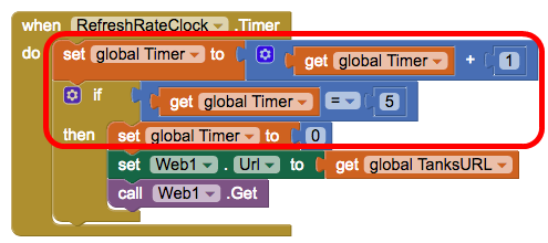
These blocks. They do not do anything useful, the timer 'RefreshRateClock' performs the actions inside the when block at intervals set by you. It will continue to infinity and beyond unless you disable it. The only block that should be in there is call Web1.Get, do not set the URL every time :)
I think you are generally on the right track Eric. It's good practice to test new things as individual "mini" Projects when defining the App, so there can be no detrimental side effects from other parts of the App to confuse the test in hand.
Kma Jack
Mar 2, 2019, 3:32:23 PM3/2/19
to MIT App Inventor Forum
and I Hi Chris,
I'll have another look for more infor on the pins extention board, maybe I understood it wrong
I deleted all the blocks from the RefreshRateClock and left just the "call Web1.Get" block but then nothing worked and kept getting "Error 1101: Unable to get a response with the specified URL: http://192.168.0.108" even after I entered the URL to the Web1 URL box in the Designer. I'll look in to that more and see if I can get it working like you said.
I actually have everything working as I wanted it except for sending the numbers. The ESP8266 (D1) does receive the number I send and prints it on the LCD as well as the Serial monitor. I can even write to EEPROM. I can see the temp/humidty readings on the web browser page and download them to the app, just can't add the number I send to that list. Never mind, after spending nearly a whole week on trying to find info on how to solve that issue, I think I am ready to give up and try to find some other easier solution.
Thanks for all your help, it is much apprected.
Eric
Thanks for all your help, it is much apprected.
Eric
Reply all
Reply to author
Forward
0 new messages