Does anyone have a good config for Pronterface/SLICR 1.0?

279 views
Skip to first unread message

Steve Prior

unread,
Apr 3, 2014, 9:55:56 PM4/3/14
to make...@googlegroups.com
I found an M2 config for SLIC3R but it was for the .9 version and I don't know if there even is a saved config file for Pronterface itself.  Does anyone have a known good PLA and/or ABS config files for SLIC3R 1.0 and Pronterface?

Thanks
Steve

A. Elias

unread,
Apr 3, 2014, 10:01:37 PM4/3/14
to make...@googlegroups.com
I can send you my KISSlicer settings if you want to try with that first.  

Adam

Steve Prior

unread,
Apr 3, 2014, 10:05:21 PM4/3/14
to make...@googlegroups.com
Sure!  I'll take everything.

Thanks!

A. Elias

unread,
Apr 3, 2014, 10:15:47 PM4/3/14
to make...@googlegroups.com
Sent you an email.  

Jin Choi

unread,
Apr 4, 2014, 1:15:07 AM4/4/14
to make...@googlegroups.com
Interesting, Slic3r had a recent release that addresses many of the problems I had with it, and includes some new features in the experimental branch: http://slic3r.org/releases/1.1.0

Eric will be interested in the ooze prevention for multiple extruders option, perhaps. I am most interested in trying out their new support generation, a perennial weak spot. The linear gap fill looks very good as well, it will squirt out single fat lines instead of trying to criss cross to fill up gaps. They also seem to have something akin to S3D's processes for different objects/regions.

Once I get my settings transferred over, I will post them here.

A. Elias

unread,
Apr 4, 2014, 1:19:37 AM4/4/14
to make...@googlegroups.com
  • New pillars support material for saving time and material and easier removal
Seems similar to the meshmixer pillar support.  

Jin Choi

unread,
Apr 4, 2014, 1:55:15 AM4/4/14
to make...@googlegroups.com
Here are my transferred settings for Slic3r 1.1.0 (experimental). They may work in 1.0.0, except for the support setting, which is set to use the new pillars.

I have not tested these, but they are based on my experience with Simplify3D, and I have run Slic3r at similar settings before with success.
Slic3r M2 settings.zip

Tim

unread,
Apr 4, 2014, 9:15:02 AM4/4/14
to make...@googlegroups.com
I run Slic3r version 1.0 and have kept using the same initialization file that I was using with version 0.9.  I have attached my init file, which contains start and end gcode blocks that were mostly developed by ketil (who posts regularly to this group).  This is a good general-purpose setup for PLA.

Given Jin's comment, I will have to take a look at version 1.1.  Undoubtedly, Jin's configuration will be better than mine.  : )
M2General098_v3.ini

Jin Choi

unread,
Apr 4, 2014, 9:31:24 AM4/4/14
to make...@googlegroups.com
One addition: add "M109 S[first_layer_temperature]" to the beginning of the start gcode. It appears Slic3r prepends startup temperature gcodes if you don't specify them, but it uses M104, which only sets the temperature and doesn't wait for the hot end to come up to temperature before it starts off.


On Friday, April 4, 2014 1:55:15 AM UTC-4, Jin Choi wrote:

Tim

unread,
Apr 4, 2014, 3:36:19 PM4/4/14
to make...@googlegroups.com
Oh, yeah, I should have mentioned that I always drive the heaters from pronterface and not from the gcode in the file.  I prefer to do that part manually.  That explains why I don't have an M109 code at the top.

Jin Choi

unread,
Apr 4, 2014, 3:54:15 PM4/4/14
to make...@googlegroups.com
So, just a followup on 1.1.0: the supports are just as abysmal as always, new pillar style or not. I like the infill patterns, though.

hilbert-infill.jpg

Tim

unread,
Apr 4, 2014, 8:32:49 PM4/4/14
to make...@googlegroups.com
Yeah, I sliced something that needed support and although I didn't print it, I could see from viewing the gcode patterns that it was no better than any other support that slic3r comes up with.  Maybe I will give in and buy Creator.

Ketil Froyn

unread,
Apr 5, 2014, 2:56:19 AM4/5/14
to make...@googlegroups.com

Since the 1.0.0 release candidates, I've actually found that slic3r's support is much improved. It provides decent support and snaps off quite nicely. I haven't tested support in v1.1.

There's currently a discussion on the slic3r issue tracker about the horizontal distance between support and the part, though. In some cases it appears to get too close and fuse pretty hard with the part. But people using soluble supports want it to always be that close. Perhaps there'll be a setting for horizontal distance.

Also note that slic3r prints support at the maximum layer thickness based on your nozzle diameter. That saves some time, especially for prints with thin layers.

Cheers, Ketil

On 5 Apr 2014 02:32, "Tim" <t...@opencircuitdesign.com> wrote:
>
> Yeah, I sliced something that needed support and although I didn't print it, I could see from viewing the gcode patterns that it was no better than any other support that slic3r comes up with.  Maybe I will give in and buy Creator.
>

> --
> You received this message because you are subscribed to the Google Groups "MakerGear - Make Today, Change Tomorrow" group.
> To unsubscribe from this group and stop receiving emails from it, send an email to makergear+...@googlegroups.com.
> For more options, visit https://groups.google.com/d/optout.

Tim

unread,
Apr 5, 2014, 9:48:37 AM4/5/14
to make...@googlegroups.com
Ketil,

It's the horizontal distance that has been a big problem for me in the past.  The last thing I printed that needed support had a hole up the center, and the support structures were indistinguishable from the walls and just made the hole a lot smaller than I intended.  There was no way to separate the two.  In that instance, I resorted to designing my own support structure.  The idea of "interface layers" between the support and the part is something new with slic3r version 1.0, and I haven't really figured out yet what are the best defaults for the interface.  What do you use?

Jin Choi

unread,
Apr 5, 2014, 10:49:12 AM4/5/14
to make...@googlegroups.com
Here's an example of the new pillar style support vs. the old rectilinear grid. The object is  M2-Extruder-Rsilvers.STL.

I haven't printed the new pillar one, but I did attempt it with the old supports, and it was basically a solid shell around the bearing hole, as if it were designed like that. The new support style looks like there might be some chance of getting it off.
Repetier-Host_Mac_0_56.jpg

John Barnhardt

unread,
Apr 5, 2014, 1:55:12 PM4/5/14
to make...@googlegroups.com
Thanks for sharing your configs, guys. I'm curious as to why you both use an extrusion multiplier of significantly less than 1... I tend to think of this as a brute force compensation for something else not being calibrated properly but assume I'm missing something here since you guys clearly know what you're doing. Thanks for any feedback.

-John

Jin Choi

unread,
Apr 5, 2014, 2:29:00 PM4/5/14
to make...@googlegroups.com
The extrusion multiplier is something that will change with different filaments, even different colors. Ideally, you should set this by printing a one perimeter hollow box for several layers, then taking a caliper to the wall and taking the inverse ratio of your measurement to your extrusion width as the multiplier (skip the first layer as it will often vary depending on your first layer height setting and your z-height zero). In practice, something around .90 seems to work fine most of the time. You can set this to 1.0, use the manual extrusion controls in the jog panel to get your infill to look right, then transfer that setting back to the multiplier.

Jin Choi

unread,
Apr 5, 2014, 2:33:09 PM4/5/14
to make...@googlegroups.com
By the way, the extrusion width, extrusion multiplier, filament diameter, and manual extrusion jog dial parameters all have the effect of changing how much filament is extruded based on feed rate (extrusion width also modifies hot end positioning). They are meant to compensate for different sources of extrusion variance. People like to caliper their filament and set the filament diameter precisely, but I like to think of it as a coarse setting (1.75 or 3mm?), and use the multiplier for fine grain fixes, since you will likely be tuning it anyway.

Tim

unread,
Apr 5, 2014, 10:02:55 PM4/5/14
to make...@googlegroups.com
I have always asserted that something somewhere has been set wrong, because theoretically the extrusion multiplier should be 1.0, and it should be expected to vary randomly around that value as the mean.  But instead it seems to be a very tight distribution around 0.9 or slightly below.  It's one of those things I could spend a lot of time investigating the origins of, or I can just set the multiplier to 0.9 and be done with it.

Dale Reed

unread,
Apr 5, 2014, 10:21:27 PM4/5/14
to make...@googlegroups.com
I'm going to speculate --- and that's ALL this is: speculation!

I think a 1.0 multiplier would be "squaring the circle" -- the volume of round filament  (pi * (d/2)**2 * extrusion length) is assumed to fill a RECTANGULAR part of the print --- if we assume a single layer thick print (e.g., bracelet), then this would  (thickness of part * layer height * length of X|Y move).  But the filament doesn't fill this volume rectangularly. (Is that a new word? YAY!)  In printing a thicker part, the extrusion is 'mooshed' in with adjacent lines of filament and 'mooshed' down to the layer thickness by the nozzle, but it doesn't fill the "rectangular" cross section.  Maybe it fills 90% of it.  (For my PLA profile, it's 94% -- probably a good estimate...)  Since you can't lay down an exactly rectangular thread, if you set the multiplier to 100%, the extra goop has to either squeeze out the sides (making the print too thick) or out the top (making the layer too thick and having the nozzle drag on it during rapids without Z lift.

My pet theory for this weekend......   Feel free to agree, dispute, partially agree, or dismiss out of hand!
Have a great weekend, all!
Dale

Steve Prior

unread,
Apr 5, 2014, 10:28:40 PM4/5/14
to make...@googlegroups.com
I've been playing with Slic3r 1.1 today and noticed it's crashed a few times, don't know if that's new to the 1.1 experimental version or if it's been buggy that way.  I'm running the 64 bit version on Windows 8.1.

I've made a lot of progress today, before now I just printed the supplied gcode examples, but today I sliced a few models and printed them successfully with just a few defects, but pretty impressive.  I still need to calibrate the dimensions so I can print that 7mm wrench that would come in handy.


--
You received this message because you are subscribed to a topic in the Google Groups "MakerGear - Make Today, Change Tomorrow" group.
To unsubscribe from this topic, visit https://groups.google.com/d/topic/makergear/g-HO5tBU044/unsubscribe.
To unsubscribe from this group and all its topics, send an email to makergear+...@googlegroups.com.

Jin Choi

unread,
Apr 5, 2014, 11:35:35 PM4/5/14
to make...@googlegroups.com
There are two 7mm hex tools for the M2 on Thingiverse. One comes in two parts that work together to hold the jam nut while the other part turns the bolt. That's if you have the nut on the top side of the platform as in the assembly instructions. Rick said recently that actually, putting it on the bottom of the platform makes it easier to access, and I've found that to be true. The other 7mm tool is a similar cylindrical wrench design, except with a 90 degree handle, I think that is useful to hold the nut without getting your hand greasy from the nearby z screw. Don't print the 7mm wrench that looks like a wrench, it works but is not as handy.

Steve Prior

unread,
Apr 5, 2014, 11:38:14 PM4/5/14
to make...@googlegroups.com
I've got the nut on the bottom as you recommended.  The cylindrical wrench was the one I was looking at.  Is there an especially good guide to calibrating the dimensions on the printer?


On Sat, Apr 5, 2014 at 11:35 PM, Jin Choi <jins...@mac.com> wrote:
There are two 7mm hex tools for the M2 on Thingiverse. One comes in two parts that work together to hold the jam nut while the other part turns the bolt. That's if you have the nut on the top side of the platform as in the assembly instructions. Rick said recently that actually, putting it on the bottom of the platform makes it easier to access, and I've found that to be true. The other 7mm tool is a similar cylindrical wrench design, except with a 90 degree handle, I think that is useful to hold the nut without getting your hand greasy from the nearby z screw. Don't print the 7mm wrench that looks like a wrench, it works but is not as handy.

Jin Choi

unread,
Apr 6, 2014, 2:10:06 AM4/6/14
to make...@googlegroups.com
Other than extrusion settings and z height, there is no need to do any calibration for the M2. Dimensional calibration is mostly necessary for home grown rep raps where you have cobbled together your bespoke gears and motors of various sizes. With standardized parts and a steel frame, all that should be identical between one M2 and the next.

Ketil Froyn

unread,
Apr 6, 2014, 4:59:05 AM4/6/14
to make...@googlegroups.com

Check out this thread on the reprap forum for pictures and formulas describing the shape of the extruded filament.

http://forums.reprap.org/read.php?263,273929,page=3

Regarding the multiplier, I think there's a number of reasons for that. PLA is harder than ABS, so the filament drive's teeth dig deeper into the ABS. In addition, I think thermal swell differs between plastics. There's probably other effects as well, so rather than trying to get the parameters perfect with a multiplier of 1.0, I think we have to accept that it's complicated and find a good fudge factor for each roll. You won't get it any more accurate than the diameter accuracy of your roll of filament anyway, where I think an accuracy of about 5% can be expected for a good roll.

A lot of "I think"s in there... This is stuff from memory and my understanding of things. I'm no authority on the subject.

Cheers, Ketil

--
You received this message because you are subscribed to the Google Groups "MakerGear - Make Today, Change Tomorrow" group.
To unsubscribe from this group and stop receiving emails from it, send an email to makergear+...@googlegroups.com.

Ed Nisley

unread,
Apr 6, 2014, 10:40:32 AM4/6/14
to make...@googlegroups.com
> find a good fudge factor for each roll.

That's exactly what the Extrusion Multiplier is: the only free variable in the whole process.

You (or the slicer) set the extrusion thickness and width, which determines the volume of plastic required per millimeter of XY motion. The filament diameter determines the volume of plastic per millimeter of filament, so, in principle, the firmware cranks in the proper length of filament during each XY motion and It Just Works.

In practice, you need another variable to account for all the other effects we can't measure: edge rounding, die swell, material shrinkage, whatever. After you plug in all the measurements, then you tweak the Extrusion Multiplier until the proper volume of plastic comes out of the nozzle, which you can only determine by measuring the result. Then you're done...

Of course, a linear factor can't account for all the non-linear effects, so the best you can hope for is to get closer to the right amount.

For what it's worth, Makergear baked a 0.9 multiplier into the firmware's steps/mm value, so the nominal Extrusion Multiplier in the slicers should work out to 1.0. The fact that everybody settles on different values isn't significant, due to all the other factors swept into that multiplier, but M2 extruder calibration starts from a different point than everybody else.

Steve Prior

unread,
Apr 6, 2014, 2:43:08 PM4/6/14
to make...@googlegroups.com
It seems to me that while the thickness of the second layer and beyond are set by the stepper motor, the thickness of the first layer is set by the Z end stop. 

The M2 documentation uses the thickness of a business card as the distance to set for the Z stop, I've got a feeler gauge - is there a more precise number I should be using?

Jin Choi

unread,
Apr 6, 2014, 2:53:40 PM4/6/14
to make...@googlegroups.com
By default, the firmware expects the end stop to be z=0 so it should be just touching. People use a small gap to compensate for thermal expansion, because it is annoying and difficult to zero when things are hot. You can also purposely leave a known gap and use gcode to set zero to the expected distance to avoid the nozzle contacting the bed ever. 0.2 seems to be an acceptable amount to leave.

Steve Prior

unread,
Apr 6, 2014, 3:01:40 PM4/6/14
to make...@googlegroups.com
Not totally clear on what you just said - do you mean I can set a gap of 0.2 and not make any gcode changes, or do I set a gap of 0.2 and need to do something in software?

Erik Akia

unread,
Apr 6, 2014, 3:28:14 PM4/6/14
to make...@googlegroups.com
Hi Steve,
you can set a negative z offset in the slicer that will shift the start point of your print depending on where your bed really is.
In Simplify3D this is done in the G-Code tab under offsets. I don't recall what slic3r calls it.

As an example, I have not moved my z-stop bolt in a very long time. When I have changes to my hardware, ei a new hot end or a new extruder, then I change the z offset to match my new conditions instead of physically changing where the stop switch is hit. Right now my offset is -.56 mm. When the print starts the bed homes and then moves up another -.56 - first layer height.

This is my personal preference on how I handle adjusting of the bed level. Some will try and get the bed and nozzle at a near zero clearance with the home switch and then the slicer will be set with no offset. Some will even get it close and then as the print starts tweak the bed height by turning the z screw as it is printing the skirt until it looks right.

Hope that answer your question.
Erik


On Sun, Apr 6, 2014 at 1:01 PM, Steve Prior <spr...@geekster.com> wrote:
Not totally clear on what you just said - do you mean I can set a gap of 0.2 and not make any gcode changes, or do I set a gap of 0.2 and need to do something in software?

--

Jin Choi

unread,
Apr 6, 2014, 3:37:16 PM4/6/14
to make...@googlegroups.com
What I meant is that you can leave offsets alone, aim for a .2mm gap when everything is cold, and that should translate to nearly zero gap at operating temperature. It is hard to use feelers between a 220C nozzle and a 100C bed.

Or you can do as Erik does. The point is, whatever you do when the slicer asks for the z height to be .1, .2, .25, or whatever, it should be that distance from the bed. You can double check this by taking a caliper to your skirts, they should be your first layer height thick (use 100% first layer multiplier).

Steve Prior

unread,
Apr 6, 2014, 4:48:11 PM4/6/14
to make...@googlegroups.com

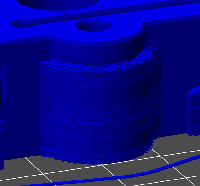
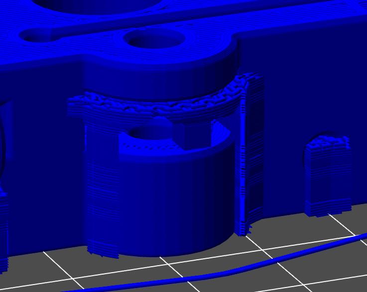
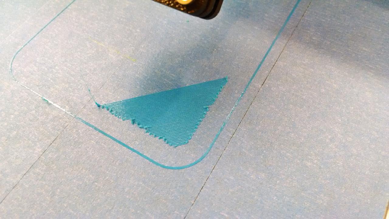
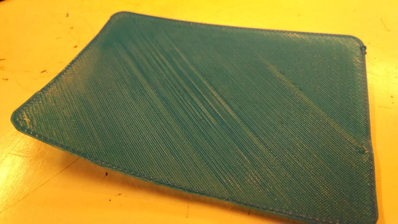
I had such an easy time yesterday printing a few things and no success at all today.  I've been using blue tape on the bed because my bed heater isn't working (bad thermistor, replacement comes tomorrow) and a PLA printing temp of 225C.  This all worked fine yesterday,  Today I can't get a clean first layer with the ends of the lines getting messed up and if I stop the print and peel up the print it's clear that the lines aren't sticking to each other, I get a spring.  Attached are a couple of pics.  Bed adhesion isn't working today and I even sprayed the tape with Aqua Net and it didn't help.  On the picture where I printed 3 layers you can see that the lines aren't fusing.

Any ideas?  My gut says raise the temperature. but I don't understand why it worked yesterday and not today (the filament spent the night in a sealed bucket with a Damp Rid in the bottom.
2014-04-06 15.26.21.jpg
2014-04-06 16.08.24.jpg

Steve Prior

unread,
Apr 6, 2014, 7:18:36 PM4/6/14
to make...@googlegroups.com
I think I got it.  I wasn't correctly measuring the head to bed gap with the feeler gauge and it was more than I thought it was, plus the Z offset setting was new to me and I've got it set now.  That Pokemon card holder my son wants which has become a whole days project is finally in the process of printing correctly.

Erik Akia

unread,
Apr 6, 2014, 7:41:07 PM4/6/14
to make...@googlegroups.com
A big part of this processes is just learning to understand what you see and what you need to change to make it work.
There are so many different variables that it can be difficult for an outsider, without the full picture, to see what is going on and give good advice.

In your picture with the layer just starting it seems to be printing the fill before the perimeter. Is that correct? This has not been my normal experience. ( I have not used anything but S3D in about a year. So I am rusty on the other slicers.)
What slicer are you using?

It is hard to tell how thick that first layer is or to know what thickness you were supposed to be getting. I would say that your extrusion multiplier is a bit low. Especially if the other picture with the more complete base represents a full layer and not a percent fill.
You can get a false positive by making your first layer height smaller to get the better adhesion but still have more problems later if you are not extruding enough plastic. Plastic will stick to plastic better than it will glass(or other stuff)  so it can seem like your only problem is between the bed and the first layer but it is more about the over all amount of extruded plastic.

Hope that helps
Erik


On Sun, Apr 6, 2014 at 5:18 PM, Steve Prior <spr...@geekster.com> wrote:
I think I got it.  I wasn't correctly measuring the head to bed gap with the feeler gauge and it was more than I thought it was, plus the Z offset setting was new to me and I've got it set now.  That Pokemon card holder my son wants which has become a whole days project is finally in the process of printing correctly.

--

jimc

unread,
Apr 6, 2014, 8:33:38 PM4/6/14
to make...@googlegroups.com
i am unsure what you guys are saying about you z-height setting. from your description what you are getting is completely opposite from me. when i have everything hot i set the gap to .15 with a feeler gauge. this is the layer height i usually print at. all my offsets in s3d are at zero. when my first layer prints, it goes down at .15 just like it should. s3d isnt assuming the gap is zero then drops the bed the layer height for first layer and then prints. it starts printing first layer at the height i have the z-bolt set to.  from what i think jin is saying is that s3d starts printing at layer 0?  atleast for me thats not the case. it starts at layer 1. am i understanding you guys right or no?

Jin Choi

unread,
Apr 6, 2014, 8:58:31 PM4/6/14
to make...@googlegroups.com
If you look at the readout in the control panel, you will see that it thinks the first layer is at your first layer height. It does not read 0 for the first layer, which is what it would do if what you said were the case.

Erik Akia

unread,
Apr 6, 2014, 9:04:55 PM4/6/14
to make...@googlegroups.com
Well I can't speak for Jin but I have my z-offset at -.56 which is really close to what I measure when everything is hot from my bed to my nozzle. (a pain to measure as your hotend is oozing)
My layer height is at .25, my first layer at .85 ratio.
After the printer starts and does the purge I have this bit of g-code.

; layer 1, Z = 0.2125
T0
; tool H0.25 W0.385
G0 X59.307 Y203.57 F18000
G0 Z-0.347 F1200

Notice that the z height is not -.56 but -.347

I should probably remove the squished first layer since I am using the hair spray which works so well.

Erik


On Sun, Apr 6, 2014 at 6:33 PM, jimc <xtremekr...@gmail.com> wrote:
i am unsure what you guys are saying about you z-height setting. from your description what you are getting is completely opposite from me. when i have everything hot i set the gap to .15 with a feeler gauge. this is the layer height i usually print at. all my offsets in s3d are at zero. when my first layer prints, it goes down at .15 just like it should. s3d isnt assuming the gap is zero then drops the bed the layer height for first layer and then prints. it starts printing first layer at the height i have the z-bolt set to.  from what i think jin is saying is that s3d starts printing at layer 0?  atleast for me thats not the case. it starts at layer 1. am i understanding you guys right or no?

--

jimc

unread,
Apr 6, 2014, 11:01:29 PM4/6/14
to make...@googlegroups.com

i hear what your sayin jin but i just did a test print to confirm. i set my z adjust screw so when homed i was at a gap of .15 or .006". this was with the bed and extruder hot. i ran a tiny print and on the first layer when it was reading .15 as the z position i stopped the print, moved the nozzle just to the side and took another reading with my feeler gauge and i was still reading .15mm/.006". all my offsets in the process are 0. i never use them. the way i am seeing things happen here is s3d just automatically starts the readout at whatever your layer height is....assuming your using 100% first layer and no offsets. 

Erik Akia

unread,
Apr 6, 2014, 11:04:17 PM4/6/14
to make...@googlegroups.com
Hi Jim,
Would you mind sharing the g-code for the test print.
Thanks
Erik


On Sun, Apr 6, 2014 at 9:01 PM, jimc <xtremekr...@gmail.com> wrote:

i hear what your sayin jin but i just did a test print to confirm. i set my z adjust screw so when homed i was at a gap of .15 or .006". this was with the bed and extruder hot. i ran a tiny print and on the first layer when it was reading .15 as the z position i stopped the print, moved the nozzle just to the side and took another reading with my feeler gauge and i was still reading .15mm/.006". all my offsets in the process are 0. i never use them. the way i am seeing things happen here is s3d just automatically starts the readout at whatever your layer height is....assuming your using 100% first layer and no offsets. 

--

jimc

unread,
Apr 6, 2014, 11:17:05 PM4/6/14
to make...@googlegroups.com
here you go.


plate.gcode

Erik Akia

unread,
Apr 6, 2014, 11:34:35 PM4/6/14
to make...@googlegroups.com
Well that is a head scratcher.
Your first z height when you start printing is in absolute coordinates and is set at .15 with this line G0 Z0.15 F1200.
I think this is consistent with what Jin and I have been saying. That after the machine homes the Z is at 0 and that should mean when you start printing at .15 that you are .15 up from the 0 point of when you hit the z-stop.

Your bed was already .15 from your nozzle when you are at your z-stop. This should mean that you would see .3 when it starts printing, which you are not.

I don't know.

Erik


On Sun, Apr 6, 2014 at 9:17 PM, jimc <xtremekr...@gmail.com> wrote:
here you go.


jimc

unread,
Apr 6, 2014, 11:49:21 PM4/6/14
to make...@googlegroups.com
yeah eric thats what was confusing me as to what you guys were saying. well in any case no need for me to really analyze whats goin on there. whatever works. i know i just set my z-stop to .006 and she is right on the money.

Jin Choi

unread,
Apr 7, 2014, 1:25:30 AM4/7/14
to make...@googlegroups.com
In theory, Erik and I are right. Now here you go introducing actual evidence to throw doubt on the matter.

I am now agnostic on this subject. I am curious as to what is going on, but I do not have the tools to investigate for myself any further, nor the need for sub-layer-precision dimensional accuracy in the z axis. So let's leave it at whatever gap will get your first layer down for now.

Jin Choi

unread,
Apr 7, 2014, 2:03:56 AM4/7/14
to make...@googlegroups.com
Having said that, a simple experiment occurs to me which might clear up matters.

Home all. Jog to the center of the bed and measure using feeler gauge. Now enter "G0 Z0.15 F1200" in the communications tab, and measure again. Does the z axis move at all when you send that command? Does that movement, if any, show up on your feeler gauge?

I can carry out the first part of this experiment myself in the morning, but not having a set of gauges I leave it to you to try the second part, if you have the time and are willing.

jimc

unread,
Apr 7, 2014, 12:49:13 PM4/7/14
to make...@googlegroups.com

i'll check that out later tonight jin.

Jin Choi

unread,
Apr 7, 2014, 1:29:44 PM4/7/14
to make...@googlegroups.com
For me, after homing and sending that gcode, the position readout reads 0.15 and the nozzle moves off the bed a perceptible amount, as expected.

jimc

unread,
Apr 7, 2014, 2:29:13 PM4/7/14
to make...@googlegroups.com
Its certainly very possible jin. Maybe when i moved my nozzle over there was some plastic on it messing with my results...who knows. Ill get on there later tonight and double check everything

Toby

unread,
Apr 7, 2014, 9:11:15 PM4/7/14
to make...@googlegroups.com
Maybe my technique with the feeler gauges isn't very good, but I notice just the act of putting the gauge under the nozzle creates some deflection in the bed because the gauge has to go in at an angle.  Or is there a different kind of gauge or technique where that doesn't happen?  

A this point I know by feel what works with the gauge I use and the way I measure it.

jimc

unread,
Apr 7, 2014, 9:22:19 PM4/7/14
to make...@googlegroups.com
if the gauge pushed the bed down then the gauge is too big and your not taking an accurate measurement. the gauge should just glide under the nozzle with just a slight friction and without deflecting the bed

Steve Prior

unread,
Apr 7, 2014, 9:24:41 PM4/7/14
to make...@googlegroups.com
Since my bed heater wasn't working over the weekend (got the replacement thermistor tonight and it works now) I was using an unheated bed with blue tape.  That was extra tricky to measure with the feeler gauge - I thought I had measured it correctly, but checked it later and it was a lot off.  It takes practice.


On Mon, Apr 7, 2014 at 9:22 PM, jimc <xtremekr...@gmail.com> wrote:
if the gauge pushed the bed down then the gauge is too big and your not taking an accurate measurement. the gauge should just glide under the nozzle with just a slight friction and without deflecting the bed

--
You received this message because you are subscribed to a topic in the Google Groups "MakerGear - Make Today, Change Tomorrow" group.
To unsubscribe from this topic, visit https://groups.google.com/d/topic/makergear/g-HO5tBU044/unsubscribe.
To unsubscribe from this group and all its topics, send an email to makergear+...@googlegroups.com.

jimc

unread,
Apr 7, 2014, 9:47:32 PM4/7/14
to make...@googlegroups.com, spr...@geekster.com
confirmed jin. the z does move down.i spent a little more time and double checked. tried it a couple times and made sure there was no plastic under the nozzle. 

Toby

unread,
Apr 7, 2014, 11:53:44 PM4/7/14
to make...@googlegroups.com
I just had a bad technique.  I was holding the feeler gauge in my hand while sliding it under the nozzle at a slight angle because somehow I got the idea it would mess up my layer of hairspray otherwise.  but i tried it just now laying it flat on the bed and that works much better.  so thanks for making me think about it again :)
Reply all
Reply to author
Forward
0 new messages