M2 HEATED ENCLOSURE CONCEPT - ideas and constructive criticisms requested

2.828 Aufrufe
Direkt zur ersten ungelesenen Nachricht

Tony Shulthise

ungelesen,
28.12.2013, 05:07:1728.12.13
an make...@googlegroups.com

I'm about ready to build this enclosure to allow printing of tall thin ABS parts without cracking or warping.  Commercial printers use a 70-90C build volume temperature to prevent this problem.  I'm looking for extra eyes to catch anything I might have missed or ideas for improvements.  All comments are welcome, especially constructive criticism.
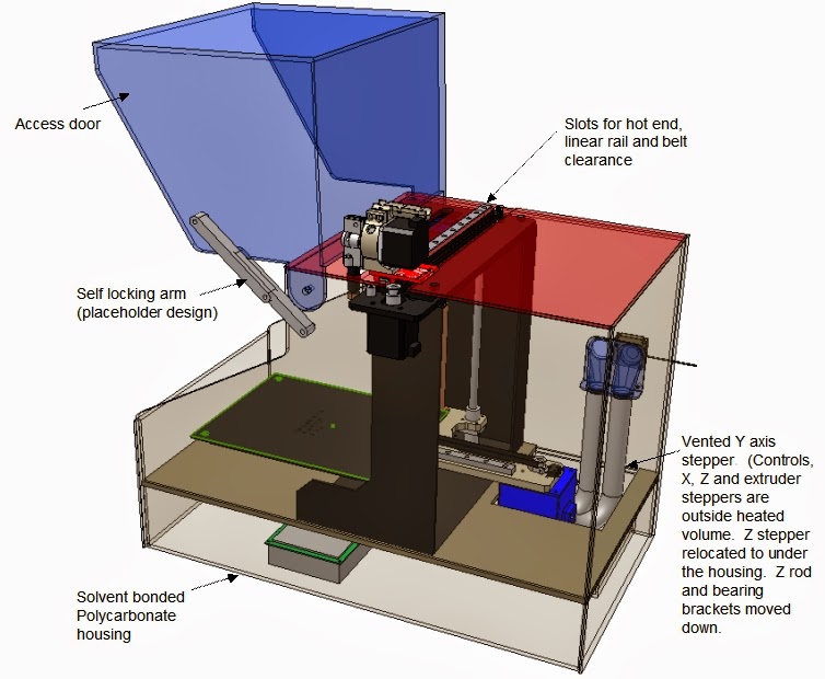
  • The enclosure will be assembled by solvent bonding 1/4" smoked Polycarbonate.  Poly or acrylic boxes are easy to make using a table saw and solvent bonding.
  • The door will have a gravity latching arm to hold it up.
  • I have the control electronics, X, Y and extruder steppers in the ambient environment so they won't overheat.  
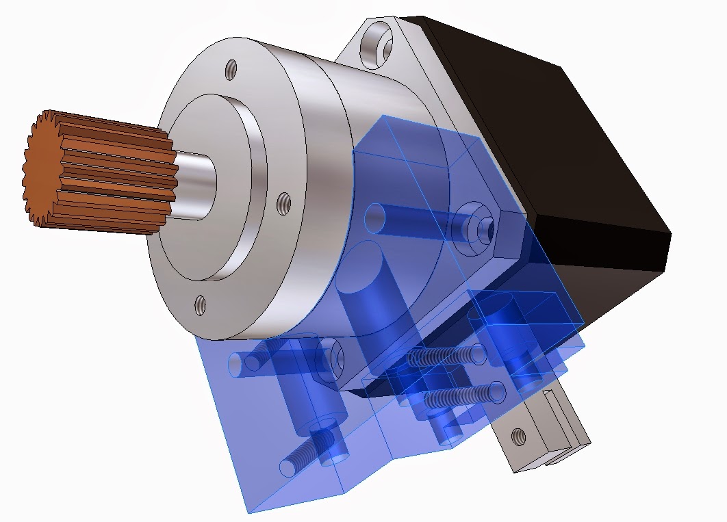
  • I added a duct system with a 40 mm blower fan to keep the Y stepper cool.  The Y stepper will be mounted in an printed enclosure.
  • I moved the Z stepper to under the stainless frame and will machine a custom Delrin mounting plate for it and the guide rails.
  • I moved the top guide rail bracket under the top of the stainless frame since the lead screw is too short to reach the original position
  • I left a volume under the housing to mount the control card, a cooling fan, power supplies, an on/off switch.
  • I'll mount the LCD control and lighted power switch on a side panel or on the access door
  • I'll add a power plug socket for a computer power cord (rated for correct amps) to eliminate a bunch of power bricks and cords running everywhere.


I have a lot more mods in this design but since the housing is the first thing I'm going to fabricate I thought it would be wise to get some feedback.

Thanks,
Tony


jimc

ungelesen,
28.12.2013, 07:43:0128.12.13
an make...@googlegroups.com
i guess i should ask how you plan to heat it? at 70c do you think the enclosure will need to be insulated to maintain those temps. i have seen poly warp over time just under its own weight at room temp so do you think the poly is going to warp with those temps?

Ed Nisley

ungelesen,
28.12.2013, 10:27:0528.12.13
an make...@googlegroups.com
I'd be sorely tempted to attach a water cooling block to each stepper and eliminate a tremendous amount of mechanical complexity: leave the motors in position, just keep them cool. Granted, you'd need an all-metal filament drive, but that's a good idea in any case.

I think the slot along the X axis will admit far too much cold air exactly where you don't want it: directly above the hottest layers of the printed object. The extruder motion will stir that air, so the temperature around the object will be much lower than the average temperature in the enclosure.

It looks like a step in the right direction: science!

Patrick Smith

ungelesen,
28.12.2013, 11:48:5728.12.13
an make...@googlegroups.com
Could you possibly use a Peltier cooler on the steppers ? Just an off the wall thought !

Ed Nisley

ungelesen,
28.12.2013, 12:40:2628.12.13
an make...@googlegroups.com
> a Peltier cooler on the steppers ?

That would also solve the chamber heating problem, because Peltier efficiency is so low!

Pulling 5 W from a stepper would require maybe 50 W of DC input power, plus a heatsink-and-fan on the hot side, so three motors would dump 180-odd W into the chamber. Ought to keep it nice & toasty-warm in there... [grin]

jimc

ungelesen,
28.12.2013, 12:53:1528.12.13
an make...@googlegroups.com
I was envisioning small dia copper tubing wrapped in a coil around each stepper with some adhesive fiberglass heat shielding tape around it. Small hoses on that going out to a small heat exchanger something like a cpu cooler

Theo McCormick

ungelesen,
28.12.2013, 14:34:3828.12.13
an make...@googlegroups.com
I've been printing in an enclosure with my M2 for some time. I did heat it with two light bulbs as an experiment. It sure helped the ABS warping. But I noticed the electrical wires got stiff and the motors ran hotter than usual. I decided to stop heating the enclosure until I could get the computer out and rewire some runs with high temp wire. Active cooling of the steppers is a great idea. From my testing I think you will see the anti warp benefits from heating the chamber starting at 45c...

Tony Shulthise

ungelesen,
28.12.2013, 15:31:2528.12.13
an make...@googlegroups.com
Thanks for the comments!!!  A few thoughts regarding some of the good ideas you brought up...  Feel free to make any counterpoints that come to mind.  That's what this discussion is for.  For such a small forum we have some pretty good horsepower here so I'm glad to be sharing with you guys.  Once I'm finished I'll be glad to share any of the designs and CAD models with those of you who have contributed.  The toughest part of all this has been reverse engineering the M2.  There are a ton of details to capture and that's taken a bunch of hours.

My main concerns:
1.  Working out a way to evenly cool PLA prints since the part cooling fan mounted on the extruder can't be used now.  I think just mountin 2 or 3 stationary fans on the top that recirculate internal air will work.  I'll add LED lighting while I'm at it.
2.  I don't know how the higher temps will affect the belt and bearings.  The stepper shaft is still directly coupled to the heat via the pulley so its going to send some heat into those bearings and the motor itself.  I haven't looked at any specs on the belts but they may lose some stiffness or possibly have lower life at higher temps.
3.  How long will it take to heat soak the system.  Starting a print before the system gets close to an equilibrium temp would probably lead to some accuracy issues.  Maybe not enough to notice.  I don't know.  I hate waiting the time it takes for the bed to heat up so this could be maddening unless I preheat well before I need to start a print.

Concerns and ideas you guys mentioned...

Plastic warping - I'm still pretty far under the heat deflection temp for Polycarbonate but if I see any sagging I'll add some external stiffeners.  I didn't use Acrylic because it has a much lower heat deflection temperature which is lower than 90C.  There aren't many unsupported horizontal panels so I'm thinking there's a decent chance I won't need to add extra supports.

Insulation - I may need to add insulation.  With a leaky cardboard box enclosure I experimented with around the entire printer it got up to around 110F (43C) with just the heat from normal operation.  Insulation on the to panels would also help with possible deflection issues with the Polycarb panels.  I didn't notice any benefit to my ABS part warping issues at 110F. 

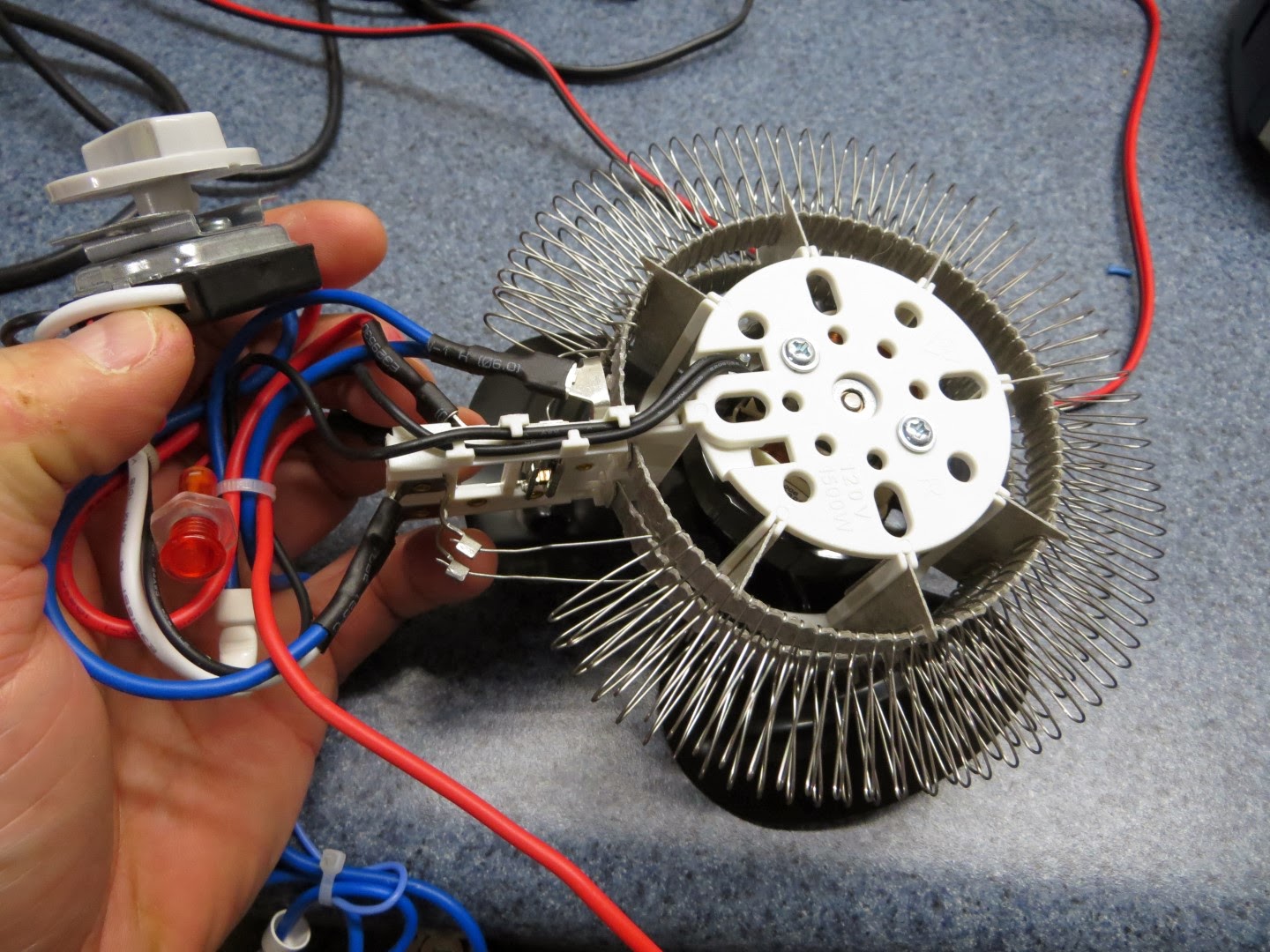
Heating - I bought a $5 toaster oven off Craig's list and took it apart.  The toaster nichrome wires are too bulky and the thermostat is designed to work in the particular configuration of the toaster so I don't think that's going to work.  So, I bought a cheap 12VDC window defroster and a cheap 500/1500 W 120VAC room heater that I'll play with to see which one gives me the best temp control.  My guess is that if I can hold 80+/-10C I'll be fine.  If not I can move to a PID control heating system which wouldn't be that expensive using an Arduino control.  I hope the simple bang-bang on/off control I'm attempting will work good enough.   I'm pretty sure I'll get what I'm looking for at 70-90C.  A 500W setting on the cheap room heater I bought should be way more than enough to pull that off.

Complexity -  My first design had the enclosure on the outside but there was quite a bit more complexity compared to this approach by the time I had to incorporate a way for cooling steppers and the extruder assy.  The only motor I'm moving is the Z stepper and those mods are relatively simple and give me over 10" of travel in the Z axis to boot.  I'll put a flex slot on the gap where the extruder pokes through so there should be negligible cold air getting in.  We'll see how that goes.  I consider it a risk but IMO its a lower risk than water cooling the hot end and extruder assembly.

Water cooling - Water vs air cooling the z stepper might be easier to implement.  I might consider that change since it would cut down on the bulky hoses and I've wanted to get some time in working on a low budget water heat exchange system.  Some copper tubing in a printed motor enclosure would work well.  Connections to the outside could be simple silicone tubing connected to a serpentine copper coil on the outside with a fan blowing on it.  The live and reliability of a water pump is much lower than a brushless fan so I'm still not completely sold on the idea.  I guess I could put two pumps in parallel to lower the chances of killing the stepper or a big print.

Peltier cooling - I've designed a couple NASA payloads using Peltier coolers and they are a great technology if you don't have much room to work with but they have some drawbacks.  Using a Peltier cooler would still require water circulation around the motor cases.  Also, Peltier coolers are good at heating but as Ed mentioned, they are very inefficient at cooling so it would likely require stacked Peltier's to get enough heat out of the motors at higher temperature deltas.  That adds cost, mass and complexity.  At least in any of the configurations I could envision.  Someone else might have a good idea that would be simple and reliable.  My goal is to be printing again by Jan 1.  My printer is in pieces right now for all the reverse engineering but I should be cutting plastic (and a little metal) tomorrow or Monday so I'm going with things I have a high confidence level in.

Wiring - Good point Theo!  I'll start this way and if the wires get stiff I'll either run them in the exit cooling duct or I'll switch over to higher temp rated wires.  The only wires that are in the heat are the Y axis stepper, Y axis limit switch, bed heater, and bed thermistor.  My guess is the only wires of concern are the stepper and limit switch wires which would be very easy to replace with a higher temp spec wire.

Please keep the discussion going.  I'll probably start cutting on Monday so I'll have time to consider any ideas that I get through tomorrow evening.  

Once this round is finished I'll start working on packing the electronics, cleaning up the wiring mess, stiffening the build platform support and increasing the build volume by around 40%.  Just having an on/off switch is going to be great not to mention all the other pluses.


Ed Nisley

ungelesen,
28.12.2013, 15:34:1628.12.13
an make...@googlegroups.com
> small dia copper tubing wrapped in a coil around each stepper

The stator stack makes "good enough" thermal contact with the end bells that I think epoxying an ordinary CPU liquid cooler to the butt end of the motor would suffice. I measured the heat transfer to an air-cooled heatsink, but a cold plate should work equally well:

http://softsolder.com/2013/03/12/stepper-motor-thermal-coefficient-vs-thermal-compound-and-forced-air/

You might want a bit of thermal insulation around the stator case, but the conductivity from air-to-case is so much less than case-to-water that it probably doesn't make much difference.

Using some flexy silicone tubing and a cable drag chain would be in order; letting the tubes flop around loose in the air can't possibly be a Good Thing.

Tony Shulthise

ungelesen,
28.12.2013, 15:40:4928.12.13
an make...@googlegroups.com
By the way, I think I can increase the build volume by well over 50% with other mods I'll post up after these. 9.5 x 10.5 x 10.1 vs. the current 8 x 10 x 8.  The biggest issue there will be finding a bed heater that doesn't cost an arm and a leg.  It will be easy to pull off for a non-heated plate for PLA though.

Tony Shulthise

ungelesen,
28.12.2013, 15:45:2528.12.13
an make...@googlegroups.com
Ed,

I absolutely love all the test data you post.  Great stuff.  Thanks for all your hard work and for sharing it!

Tony

Ed Nisley

ungelesen,
28.12.2013, 16:30:0328.12.13
an make...@googlegroups.com
> all the test data you post

They say one careful measurement is better than a thousand expert opinions. I figure my measurements are good for a few dozen opinions!

Thanks...

Ed Nisley

ungelesen,
28.12.2013, 16:52:0528.12.13
an make...@googlegroups.com
> two pumps in parallel

Figure you're pulling 20 W from the motors, so allowing the water to rise 5 C = 5 K requires only 1 g/s = 1 cc/s = 1 gallon/hour. I think I have my units right: water is 4.1 J/gK, so it's (20 J/s)/(5 K * 4.1 J/gK) = 1 g/s and a gallon is 3800 cc, which is approximately 1 cc/s * 3600 s/h.

That ignores some heat transfer in the motors, but it's close enough for a first pass.

So a cubic foot of water is good for eight hours of printing: build a cubic foot box from your scrap polycarb, put a barb fitting in the bottom, fill it with cold water, and you're good for eight solid hours of printing without a pump. If you're fussy, build a sump, put a float switch in the top box, and keep it full; if the pump fails in mid-print, you're still good for another eight hours.

What's not to like?

jimc

ungelesen,
28.12.2013, 17:11:1528.12.13
an make...@googlegroups.com
Figure you're pulling 20 W from the motors, so allowing the water to rise 5 C = 5 K requires only 1 g/s = 1 cc/s = 1 gallon/hour. I think I have my units right: water is 4.1 J/gK, so it's (20 J/s)/(5 K * 4.1 J/gK) = 1 g/s and a gallon is 3800 cc, which is approximately 1 cc/s * 3600 s/h.

ummmm...ok ed lol. have to take your word on that one buddy!

Tony Shulthise

ungelesen,
31.12.2013, 14:52:5131.12.13
an make...@googlegroups.com
I'm rethinking the idea of using a portable room heater guts to heat the enclosure.  I'm guessing even at the lowest setting its going to run the temp up too quickly to cut off in time to maintain an acceptable temp hysteresis.

Does anyone know many watts the bed heater draws (average wattage to maintain 100C)??  My guess is that 2-3x that amount will get me in the right ballpark to maintain the enclosure at 90C.

I'm wondering if something as simple as a fan and couple 50W power resistors switching on and off would do the trick?  The thermostats on toaster ovens and portable heaters just use a temp sensitive metal relay that toggles at various temps based on how much tension is put on it by the thermostat adjustment knob.

Any thoughts a good way to make a compact heater that's reliable and accurate enough to hold +/-5C?  

Thanks,
Tony

jimc

ungelesen,
31.12.2013, 15:04:0631.12.13
an make...@googlegroups.com
tony, have you seen the 3 youtube videos of the guy who built the heated enclosure. he heated it with a bed heater mounted to the side wall and a couple 100 watt light bulbs or something like that anyway. do a search. you should be able to find it

A. Elias

ungelesen,
31.12.2013, 15:07:2631.12.13
an make...@googlegroups.com
For my 12V bed heater, I was measuring a resistance of around one ohm, so 144W is what my bed heater was pulling during warm up.  You can easily measure this by taking the cover off the electronics, unplugging the heater connector from RAMBo and using a DMM to measure resistance.  I may measure it again just as a sanity check when I get home.  

Ed Nisley

ungelesen,
31.12.2013, 19:25:1231.12.13
an make...@googlegroups.com
> 50W power resistors

Remember that power ratings drop linearly as ambient temperature increases and there's a hard upper temperature limit. Makerbot ignored that in their MK5 extruder:

http://softsolder.com/2010/12/26/makerbot-thing-o-matic-mk5-extruder-resistor-abuse/

For an ambient temperature of 100 C, figure maybe 50% derating for a ceramic resistor: a 50 W resistor might dissipate no more than 25 W. Higher reliability = more derating, as always.

You have a spare build platform heater, yes? Epoxy a really big heatsink to the heated side, apply a fan, and you'll be in the right ballpark: large surface area, relatively low temperature differential, high airflow, rugged construction, decent connectors.

Marlin / RAMBo can handle two extruders, so I think you could gimmick up a second thermistor and manage the heater as a new "extruder". I'd use a DC-DC SSR to get the load current off the board, but that's in the nature of fine tuning...
Die Nachricht wurde gelöscht

Tony Shulthise

ungelesen,
01.01.2014, 11:23:0001.01.14
an make...@googlegroups.com
Thanks for the good info (again) Ed!

I ran some quick numbers and it looks like I would need around 2000W of power to get up to 90C unless I add some insulation.  Looks like I will have to add some insulation to the design.  I'll insulate the inside of the top and side panels behind the M2 frame, and under the bottom panel.  That should get me down to well under 1000W and the heated bed and hot end will give me some of that.  I'll keep adding insulation until I get it around 500W average power through the heater.  I may need to make a tighter slit for the hot end than I planned on.  I might use a very light sliding piece to close the gap (think roll top desk).  I wish I would have run the power numbers up front.  I would have probably just pieced together some foam panels to test everything before designing the enclosure.

RAMBo control and amp -  I never thought about using the extra extruder circuit for the heater control.  So I guess the DC-DC-SSR would act like an amp and the thermistor feedback would give me PID control through the RAMBo.  That seems like that would be perfect after I work out the constants.  Thanks for the idea!  I used a DCDC converter for a low power project once and that worked out fine.  I wonder is Sparkfun or Pololu might have a circuit available that would do the trick for this one?  I'm would want to have a 1000W converter just to be sure I have enough margin.

Other heater ideas - I knew about derating resistors and motors but would have not remembered.  Thanks for that reminder also.  

Toaster oven - I could use the resistive material from the $5 toaster oven I bought.  The toaster oven has 2 @ 25 ohm 11" long (coiled) heating elements (Nichrome wire??) wired in parallel, each inside a glass tube.  I'm assuming I can cut them to whatever length I need to get the power I want and just duct the blower air through and around the glass tube. Since I will need over 500W I might just keep them as is and see how much they cycle at the peak temp.  I'll just make a double wall sheet metal enclosure and blow air inside and between the walls so nothing gets too hot.

Portable electric heater - I took the portable heater apart and its just way to big and bulky to use.  I could probably use the resistive wire in it though.  Its really the exact same setup as the toaster oven except it uses a different resistive wire configuration.  Same wiring schematic and same thermostat type.

12VDC portable window defroster - I forgot that I had bought a 12VDC portable windshield defroster.  Its basically just a blower and three pieces of some kind resistive material connected to a heat sink.  It measures 2.5 ohms.  That's only 60 watts using the 12VDC power supply. That won't be enough heat.

 I'll attach pics of each.  


Any more thoughts after all of that?  Thanks for all the great feedback!

Tony

Theo McCormick

ungelesen,
01.01.2014, 13:01:3501.01.14
an make...@googlegroups.com
I did test a Harbor Freight heat gun. Basically a hair dryer on steroids. It was loud and slower than you would think but it heated my chamber up just fine. 1500 watts I think. I ran it outside and vented the hot air in. 

I also looked at 'heat bars' that I could mount over the print bed. This is similar to the toaster elements but available in watts per inch measurements. They looked promising but I did not try them. I was looking to heat the print with radiant heat as opposed to using convection by heating the air.

I am running a vent fan at the same time so there is a lot of heat going up the vent.

Ed Nisley

ungelesen,
01.01.2014, 13:21:0501.01.14
an make...@googlegroups.com
> around 2000W of power to get up to 90C

A somewhat larger box in the basement made of aluminum faced foam insulation runs at 65 C with 120 W, so reaching 90 C would require about 660 W. Your box has maybe 2/3 that surface area, so I'd expect 400 W would suffice. Of course, a foam box won't be nearly as pretty.


> want to have a 1000W converter

For those power levels, I think the only choice is an AC line operated heater of some sort. That lets you use an ordinary DC-AC SSR (look for SSR-25DA on eBay); the RAMBo will be perfectly happy on the DC side. I dislike running line voltage around homebrew projects, but with great care and much electrical insulation it should be OK.

But the trouble with toaster ovens & similar resistive elements is that they run way too hot and require tremendous airflow to cool them. I'm not convinced a hot tornado around the build platform will produce Good Results.

jimc

ungelesen,
01.01.2014, 14:53:2701.01.14
an make...@googlegroups.com
how about 1 or 2 500w work lamp bulbs. small and compact. not sure of the longevity but they are only a couple bucks, readily available and easy to replace.

Dale Reed

ungelesen,
01.01.2014, 15:02:0101.01.14
an make...@googlegroups.com
Tony,

You can get a dedicated single-loop PID temperature controller, platinum RTD probe (or thermocouple) and solid state relay with heatsink from Amazon (and others).  I got this setup:


Total cost: under $50 USD (shipped to U.S. destinations).

... but I haven't fired it up yet.

A platinum RTD is very accurate -- better than a good thermocouple -- much more accurate than you'll need for enclosure temperature control.  The probe mounts in a single drilled hole and is threaded and comes with the nut for the purpose.

Just offering another alternative --- and fairly easy (the controller has a language-free instruction sheet --- but I trust you can decipher it!!!) and reasonably inexpensive.

Dale

Tony Shulthise

ungelesen,
01.01.2014, 17:36:2001.01.14
an make...@googlegroups.com
I'll check that out Dale.  I don't mind the temperature control being stand alone and I've actually used a unit like this in the past and it was very accurate after I tuned it.  It was just a lot more expensive than this one.  I can't believe you can get them that cheap now.  Great info guys.  I'll keep you posted on my progress.  Thanks again for all the inputs!

Tony Shulthise

ungelesen,
01.01.2014, 17:38:2501.01.14
an make...@googlegroups.com
Only problem is that unit doesn't carry enough power for what I'm doing.  I'll poke around and see if there are any 110VAC 8 amp units at that price though.  Automation direct might have something too.  I never thought they would be that low in price so I didn't ever bother to look.

Ed Nisley

ungelesen,
01.01.2014, 19:57:2601.01.14
an make...@googlegroups.com
> that unit doesn't carry enough power for what I'm doing

The DC-AC SSR appears to be the same as the ones on eBay: the 25 A rating will get you to 3 kW at 120 VAC, which should suffice for an AC line powered heater.

You could swap in an 80 A DC-DC SSR (for another $30) and a hulking DC power supply (for much more), but IMO this is one of the few cases where AC line power makes sense...

Tony Shulthise

ungelesen,
01.01.2014, 22:23:4701.01.14
an make...@googlegroups.com
What do you think about this one? It looks like a "bang-bang" type but wouldn't that be fine for what I'm doing?  Only $18, good reviews and includes two 10A 120VAC relays and a temp probe.

A. Elias

ungelesen,
01.01.2014, 23:11:1301.01.14
an make...@googlegroups.com
Looks pretty nice for $18...  

quaverf

ungelesen,
07.01.2014, 22:54:1207.01.14
an make...@googlegroups.com
Great discussion.  I am anxious to see how your project turns out Tony; I have been thinking about a heated build chamber myself given some of my early print results (delamination, warping, etc).

Tony Shulthise

ungelesen,
09.01.2014, 06:07:4409.01.14
an make...@googlegroups.com
I was hoping to finish it while I was off for Christmas break but didn't. It will be a little slower going now that I don't get full days at a time to work on it.

I've decided to build the enclosure first then run tests to determine exactly how much heater power I will need. Once you get over 500 watts or so, the heater design gets tricky because the outlet temperatures get relatively high. I'll design my heater to use only the power needed to maintain 90C.

I'd say I'm 90% through the design plus any heater mods that come later. I'll keep you posted as I move forward.

Tony Shulthise

ungelesen,
13.01.2014, 21:55:5013.01.14
an make...@googlegroups.com
Question for you guys...

I'm trying to pack the two brick power supplies in the base of the enclosure and I really don't like using this kind of power supply.  If I switch to a 24VDC power supply like the ones they are using for the new M2's are there any firmware changes required?  I'm pretty sure they are PWM'ing the 19V supply for at least one of the fans.  I don't know if the stepper drivers are current limited or not.  I also don't know anything about how the hot end is driven.

I have the new version hot end now.  Will it work with the old power supply and-or  24V?  I don't know if the old hot end ran off the 12V or the 24V supply.

Any info would be appreciated.

Thanks,
Tony

jimc

ungelesen,
28.01.2014, 12:32:4728.01.14
an make...@googlegroups.com

jimc

ungelesen,
28.01.2014, 12:39:1828.01.14
an make...@googlegroups.com
 i dont think i could buy all the materials and make it myself for the cost of that.

Tony Shulthise

ungelesen,
28.01.2014, 17:16:4428.01.14
an make...@googlegroups.com
I love the idea for the cabinet in general and it might be worth the $$ just because it will give a controlled printing environment.  It would be great for drying paint and making silicone molds and castings too.

Several months ago I put a case around my M2 and found that, even at 105F, tall ABS prints still had serious warping issues.  From what I can find it may take closer to 170-190F to eliminate that issue.

Something to consider with one size fits all cases is that anything over 100F will probably cause reliability issues with the motors, guides and/or controls.  That means they have to be outside the case or actively cooled in some way (vented or water cooled).  I think a nice product that could go along with this Kickstarter case would be a easy to install, reliable stepper motor cooling system.  A one size fits all case with the ability to cool components is really the only practical way to retrofit a printer to print at high temps.  Building a custom enclosure is VERY time consuming.  I'm not sure I'd do it again.

With the exception of the Y axis stepper and linear bearing, my M2 enclosure design puts the controls, motors and one of the rails outside of the heated volume which will allow me to heat it up to near 100C without any reliability issues.  I'm switching the Y rail out for a longer one rated for 100C and which also has preloaded bearings to improve accuracy.  I'm air cooling the Y axis stepper.

Thanks for sharing the Kickstarter link.  I love keeping up with anything entrepreneurial!  I'm still plugging away at my design.  As I got close to the point where I thought I was ready to cut plastic I realized I needed to model every detail of the M2 or I was going to end up with issues that wouldn't be easy to resolve after solvent bonding the housing together.  I'm getting close now though.  My build volume is nearly double the stock build volume now with just a few changes to the stock design.

If any of you guys have any insight regarding my 24V power supply question posted on Jan 9, I'd appreciate any insights you might have.

Thanks!
Tony

jimc

ungelesen,
28.01.2014, 18:26:3828.01.14
an make...@googlegroups.com
Tony, check the m2 update thread. Rick recently listed the changes needed to upgrade from 12 to 24v on older machines. It depends in what rambo you have. Also depends if you have a 12 or 24 cartridge in your hot end. The different firmwares for different voltages are listed in the wiki

jimc

ungelesen,
28.01.2014, 20:04:5028.01.14
an make...@googlegroups.com
for anyone interested i contacted the manufacturer of that enclosure. its made from 16 and 18ga steel or stainless. whichever you choose i guess. thats pretty beefy. for the price i was worried it would be some super thin crappy cabinet. comes with a pid controller as well for heating it. 

tony im sure cooling the steppers is a must with a heated enclosure like that. i think that would be the easiest thing to do really. the biggest thing if you were to fully enclose and heat the m2 would be the filament drive and extruder motor mount would need to be metal or that is going to droop

Tony Shulthise

ungelesen,
29.01.2014, 23:18:0929.01.14
an make...@googlegroups.com
Thanks for the info Jim!  I'll check that thread out.

For my enclosure, the extruder drive, X-rail, and the lead-in to the hot end are all outside of the enclosure.  I'm almost certain that the hot end would clog if used in a very hot enclosure unless it was also water cooled.  

The M2 Rails aren't rated for very high temps either.  I'm changing my rails out for longer rails that are preloaded to take the small amount of wobble out.  They are also rated for 100C operation.  The longer rails give me 50% more print area (9.75" x 12.175") and almost 70% more print volume (9" Z travel with a couple other changes) without having to do much cutting on the OEM setup.  I'm excited to finally be close to finishing the painful final details of the design.

Thanks again,
Tony

A. Elias

ungelesen,
30.01.2014, 08:06:5830.01.14
an make...@googlegroups.com
Tony,

Are your new rails drop in replacements with regards to holes in the z-axis support part the current rails sit on and spider arm?  I've been watching mine and I'd like to look into the pre-loaded linear rails to help reduce some movement during fast moves.

I don't have easy access to a CNC machine so I'm limited to finding options which are drop in replacement.  

Lastly, if they aren't drop in replacements could you give me a few hinters on what mfgs to look at?  I checked out mitsumi briefly, but I think I need to spend a little more time exploring their website. 

ADam

Tony Shulthise

ungelesen,
31.01.2014, 00:12:5331.01.14
an make...@googlegroups.com
Elias,

Sort of... if you buy the same length rail as you have now its pretty close to a drop in replacement.  Its the same rail profile and hole pattern.

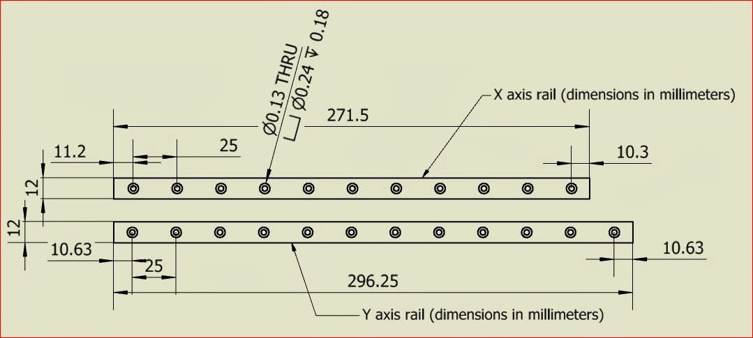
I noticed that the X axis M2 rail has been cut so one end sticks out a little further past the last hole than the other end.  The OEM M2 rails are 296.25mm for the Y axis and 271.5 mm for the X axis.  The 295 mm and 270 mm Misumi rails should be drop-in replacements.  Check HERE for more info. WARNING... I haven't received the preloaded rails yet and I'm not sure how high the friction force is going to be.  Its possible that the preloaded rails may have more friction than the M2 steppers can handle.  Misumi lists some specs. for this but they are contradictory so I'll need to get the rails myself to be sure.  I'll post results when they come.  I hope to have them here to test within the next week.

I'm replacing both of my rails with longer, preloaded, high temp rails (Misumi PN SSEBT13-345) to get more travel and to work in the heat. They cost around $90 each.  The route I took requires drilling one extra rail hole for the Y axis rail and two extra holes for the X axis rail.  I will also have to relocate my limit switches and end stops and reprogram the firmware for the new travel limit values.  I also have to rework the belt connections on both and relocate the belt bearing for the X axis and add an idler pulley to take up the slack (or I may just use an open ended belt and clamp it after pre-tensioning it).

I'll be glad to answer any questions I can to help you out.

Tony

est1983gmail

ungelesen,
02.02.2014, 05:51:5802.02.14
an make...@googlegroups.com
I've been looking for rails to reduce the small amount of play I get - thanks for posting that.

Are you using a larger bed too then?

Tony Shulthise

ungelesen,
02.02.2014, 15:02:0902.02.14
an make...@googlegroups.com
I'm going to modify the aluminum part that holds the bed so I can also interchange a magnetically mounted larger print bed.  It should be good for PLA parts.  I'm not sure I want to get into the cost of having a heater made to fit the larger plate which may or may not be be needed to use it for ABS parts in a heated enclosure.  The new build plate area is 12.175" x 9.75" (40% increase in printable area).

The M2 rails are low quality as linear guides go.  That was probably needed to keep prices competitive.  A quality linear rail system shouldn't have any noticeable play in it.  The jury is still out on using the preloaded rails... they may have too much friction.  I hope to have them in this week to find out.  If the preloaded ones prove to have too much friction then I'll just go with precision grade with no preload. I'm pretty sure precision grade rails have zero play even without preload. The main advantage of preload is to lessen deflections under load.  

Tony Shulthise

ungelesen,
13.02.2014, 22:24:5513.02.14
an make...@googlegroups.com
Good news, the preloaded Misumi linear guides came today and they don't have any play whatsoever.  

They also don't have any noticeable static friction and the moving friction is very low even with the preloaded bearings.  I measured around 45 grams moving force with the rubber wipers in place and around half that much without the wipers.  That force is a function of speed however.  Part of the force is due to the thicker high temperature grease (100C rating) which will thin out a little at higher temps.  Even if it didn't there is no noticeable sticking on startup which is all that I was concerned about.  I'm very pleased that they have such low force even with the preloaded bearings.  It should make for a much stiffer, super precise setup.

jimc

ungelesen,
13.02.2014, 22:29:2313.02.14
an make...@googlegroups.com
tony just for future reference and for anyone who may decide to change their slide would you be able to look up and give us a part # for the same slide you bought that would be the direct replacement for what is stock on the m2?  

Gregg Bone

ungelesen,
14.02.2014, 10:30:0314.02.14
an make...@googlegroups.com
I suggestion on heaters.  Many of us have or are about to upgrade our bed heaters to the new larger 24Vpower supply M2.  That means we have the old bed plate with silicone heater attached laying around collecting dust.  5 of those in series would make a perfect 120v heater - and nice and evenly distributed heat.

Tony Shulthise

ungelesen,
15.02.2014, 21:06:0615.02.14
an make...@googlegroups.com
Gregg... I like the idea of nothing getting much hotter than the air temperature but my guess is that the bed heaters are on the order of $50 each, or more.  Any idea how much they cost?  My current plan is to use the heating elements from a $5 toaster oven I bought off of Craig's list and place them in a double walled sheet metal enclosure with a 15 CFM blower to keep the temps from going too high.  I'm using a $20 "bang-bang" controller with a thermocouple input to control the temp.

est1983gmail

ungelesen,
17.02.2014, 17:32:1717.02.14
an make...@googlegroups.com
Ah man, I just tried to register an account and they have a very limited countries drop down list which doesn't include UK :(


On Friday, January 31, 2014 6:12:53 AM UTC+1, Tony Shulthise wrote:

est1983gmail

ungelesen,
17.02.2014, 17:50:0117.02.14
an make...@googlegroups.com
found Misumi europe, but they only sell to businesses and not individuals - most irritating!

Tony Shulthise

ungelesen,
17.02.2014, 22:41:1617.02.14
an make...@googlegroups.com
I'm pretty sure you guys can find equivalent guides through a THK distributor. THK and a few other companies make quality guides. The M2 block, rail profile and hole pattern are standard. I'm not sure the lengths are. I didn't check.

Remember that the part number I listed is a longer travel than stock which requires some mods to work. You could also replace the stock M2 guides with ones near the same size. The stock Y rail is longer than the X rail.

Stiffening up the bed mount is probably the first thing to work on before replacing the linear guides since there's more compliance there than in the guides.

jimc

ungelesen,
17.02.2014, 23:26:2817.02.14
an make...@googlegroups.com
tony, do me a favor and double check me here...so if i understand misumi's part # system right then the correct "Y" replacement rail according to your measurements would be SSEBT13-295? 

Tony Shulthise

ungelesen,
18.02.2014, 18:07:1018.02.14
an make...@googlegroups.com
Jim, sorry about missing your last post somehow.  I don't know how I missed that one...

I can't find a guide to decode Misumi's part numbering system but the last number is the rail length in millimeters.  You can also have the rails cut shorter on one or both ends.  Here's more info on the heat resistant type of rail systems.  https://us.misumi-ec.com/vona2/detail/110300047020/

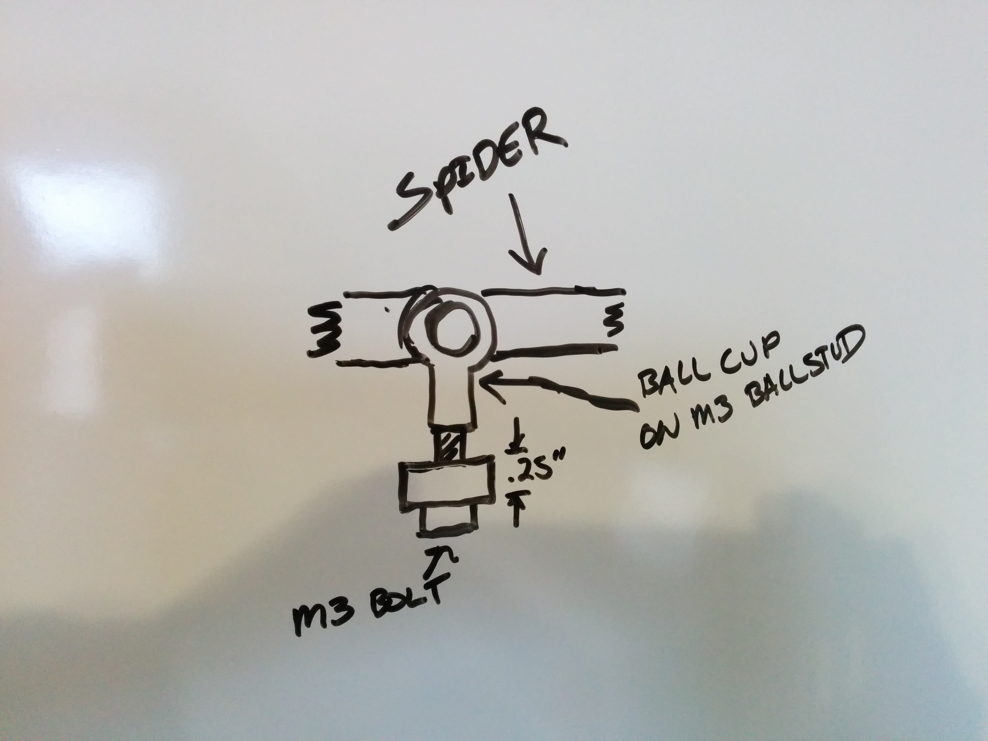
The stock M2 X and Y rails are different lengths and the X rail has one end cut.  I'll attach a diagram showing what I measured and modeled.  Keep in mind, the picture below shows what I measured from my printer parts with calipers.  These are not super precise measurements.  If you go to the Misumi PN I posted earlier you will get exact dimensions for things like the rail profile, overall height, exact hole and counter bore dimensions, etc... 

jimc

ungelesen,
18.02.2014, 19:23:2818.02.14
an make...@googlegroups.com
ok tony, yeah i looked at the # you said that you ordered then changed the # for the rail length. i double checked all the measurements on misumi's website and it looks like that is the one. i am not really interested in the"x" rail. its the "y" that could be a little more snug. so SSEBT13-295 should be a drop in replacement for the stock "Y" rail. if it has no play like you say then that would be great. then its just a matter of a slightly beefier bracket that mounts the spider to the rail block. i would think that between the two and combined with the lower acceleration settings you would be able to get rid of most of any resonance. or atleast improve it greatly.

Tony Shulthise

ungelesen,
18.02.2014, 23:04:2618.02.14
an make...@googlegroups.com
Jim, I measure the Y rail at 296 mm.

Tony Shulthise

ungelesen,
19.02.2014, 23:41:4719.02.14
an make...@googlegroups.com
I forgot to mention, to get the drag as low as the stock linear guides I removed a rubber wiper that was attached to each end of each guide.  The rubber wipers added about 25 grams of extra static friction.  It wasn't much but I'd rather not have to wonder if that was causing a problem or not.  

The stock M2 guide doesn't have a wiper so removing this wiper should not decrease the longevity or performance for the M2.  I suggest not printing in a very dirty or really dusty environment.  Covering the X rail with something when you aren't printing will keep typical ambient dust from accumulating in the bearing grease over time.

Robert Silvers

ungelesen,
23.02.2014, 20:20:3223.02.14
an make...@googlegroups.com

Tony Shulthise

ungelesen,
25.02.2014, 05:49:2325.02.14
an make...@googlegroups.com
Robert... I'm using the Elitech STC-1000 temperature controller from Amazon. It's only $17. I haven't tested it yet so I don't know how well it works or how reliable it is. We shall see.

Tony Shulthise

ungelesen,
05.03.2014, 16:23:1105.03.14
an make...@googlegroups.com
Update on the preloaded linear bearings...

To my surprise, I can still feel some play in the linear bearings. I can't feel any play when I grab the linear guide block and try to wiggle it but once I hard mount the spider and build plate frame I can definitely feel play.  It feels similar to the stock M2 rails but about half as much.  I was going to measure the deflection but after playing round with the system I can see that we get a lot of deflections from a number of sources so its probably not worth the effort to try to figure out how much comes from each component:

1.  Linear guide block play.  At this point I'm starting to understand why most systems use 4 cylindrical bearings on rods.  Its probably a more accurate design if its set up correctly.
2.  Bed mounting plate and spider deflections.  These parts just are not thick enough to prevent significant deflections when only one mounting point is used.
3.  Z axis guide rods.  One size larger or possibly having guides on both sides like some other systems use would have been much more solid.
4.  Even the extruder mounting bracket is somewhat flimsy.  However, I'd guess it introduces the least amount of error.

Ed Nisley

ungelesen,
05.03.2014, 21:24:1505.03.14
an make...@googlegroups.com
> 4 cylindrical bearings on rods

It's really hard to make a good, cheap kinematic mount with four sliding bushings. A mount with two sliding bushings and a rolling rotation control seems better, but it looks tacky... and that counts for a lot.

Somebody showed me a hulking printer with a platform with (what looked like) sliders on four vertical rods at the corners and driven by two leadscrews on the long sides. It wasn't obvious how they built a kinematic mount with all those constraints; there weren't any visible adjustments and they didn't tout how they pulled it off.


> Bed mounting plate and spider deflections

I think the forces and torques imposed on the platform during operation are lower than we apply while wiggling things manually, but it'd be tedious to work them out in detail. The XYZ accelerations range from 0.20 to 0.50 G on my system, so the forces should be a quarter to half the dead weight; the stock platform and Y-axis stage weighs around 2 kg, so we're talking a pound, tops.

With my modified silicone-pad platform mounts, I see about ±5 mils = ±0.125 mm of slop parallel to the X axis when pushing not-too-hard on the edge of the platform, which isn't enough to worry about. In any event, there's no way to impose offset forces on the platform in the XY plane during normal operation.

There's less than that in the Z direction, again at the end of the plate with gentle pressure, which would be maybe half of a 0.20 mm layer thickness; I've never seen imperfections that large in the tops of extruded threads. Those forces would come from the offset between the platform center-of-mass and the Y-axis linear bearing, which has the lowest acceleration of the three.

The stock spring-mounted platform, on the other hand, will have far more slop due entirely to the wobbly screws and spring loading, even with those low forces. All bets are off in that case!

I've been bringing my old Thing-O-Matic back to life with a new controller and, wow, I'd forgotten how non-rigid that thing was... [grin]

Tony Shulthise

ungelesen,
06.03.2014, 09:39:0606.03.14
an make...@googlegroups.com
With the spider and bed mount hard mounted to the guide block I'd guess that deflections in the metal parts of the print bed mount would be in the 0.030" range for a 1 lb force applied a couple inches off center.  I'll do a check once I get everything running and we can compare notes.  To get a perfect looking print that number probably needs to be closer to 0.005" or less.  Again, just a guess on my part.

My TAZ has at least 5x as much compliance as the M2 and it still can produce some decent prints.  It really does amaze me how much can be done even without really tight mechanicals.

I need to update my firmware now to account for:
1.  24VDC PS
2.  New version hot end
3.  Longer travel for x, y, and z
4.  Bed sensing z-home switch (not totally worked out yet)

I found the wiki for updating for the new PS and hot end.  Any good links for how to adjust travel limits and sequences for z homing?

Thanks for all your feedback Ed.  I always enjoy reading your posts and responses.  There are several other great resources in this forum too.  ...Keeps me coming back.

Curtis Menard

ungelesen,
06.03.2014, 10:14:5906.03.14
an make...@googlegroups.com
I've thought about removing the leveling springs and going with a solid mount using 3 ballcups and ballends mounted to a .25" support.  I'm thinking that without the springs the vibrations wouldn't affect the bed as bad.  I've attached a picture from my white board... don't laugh.


--
You received this message because you are subscribed to the Google Groups "MakerGear - Make Today, Change Tomorrow" group.
To unsubscribe from this group and stop receiving emails from it, send an email to makergear+...@googlegroups.com.
For more options, visit https://groups.google.com/groups/opt_out.

IMG_20140306_101003.jpg

Bryan Boettcher

ungelesen,
06.03.2014, 10:25:0806.03.14
an make...@googlegroups.com
Guys just turn your accel down.  It doesn't affect the print speed all that badly and it does improve print quality in several types of features.  You can still set high travel speeds.

I run 800mm/sec^2 & 40mm/sec on my prints, and the 40mm/sec is the limiting factor by a lot in terms of print speed.

A. Elias

ungelesen,
06.03.2014, 10:40:0606.03.14
an make...@googlegroups.com
I do 40mm/s at 1500mm/s^2 for perimeters and 120mm/s at 1500mm/s^2 for infill and support.  I use g-code startup code to set the accelerations.   

Sometimes I go through and use regular expressions (notepad++) and modify the infill and support to 9000mm/s^2 for long prints. For an 11 hour print this can decrease the print time by more than an hour.  

Adam

Bryan Boettcher

ungelesen,
06.03.2014, 10:51:2306.03.14
an make...@googlegroups.com
If I have an 11 hour print it's probably running overnight and then I don't care if it takes the extra hour.  There have been very few instances where I actually needed to cut an 11 hour print down to a 10 hour print, although I'd be lying if I said there were none.

A. Elias

ungelesen,
06.03.2014, 11:01:3106.03.14
an make...@googlegroups.com
:-)

Just putting it out there.  If you you need to keep the printer going and have it work around your schedule that is a lever to play with...  All depends on your use case.  Printing is a hobby and small income for me...  

My example is, you leave for work at 7:30am in the morning, but your printer takes 11 hours to complete, it finishes right at 7:30am so it leaves you no time to kick off the next print..  Adjust the acceleration and you have an hour window before you have to leave as it would finish at 6:30am..  It takes one minute to run the regular expression search and replacement to gain one hour of leeway.  All depends on scheduling and planning.  

ADam

Ed Nisley

ungelesen,
06.03.2014, 12:16:0406.03.14
an make...@googlegroups.com
> Any good links for how to adjust travel limits and sequences for z homing?

The limit parameters are buried in Configuration.h, but the sequence is hard-coded in Marlin.ino. I haven't changed those, as I control the entire (highly customized!) homing sequence in the startup G-Code; it's easier than fiddling with firmware.

And, yeah, I've made quite a few original mistakes along the way... [grin]

Tony Shulthise

ungelesen,
06.03.2014, 15:28:2206.03.14
an make...@googlegroups.com
Any good links that show, in detail, commands to use and how to change the following in the S3D scripts?

3.  Longer travel for x, y, and z
4.  Bed sensing z-home switch (not totally worked out yet).  Will probably involve moving x off the bed as in the start of the wipe sequence but a tad further, raising the bed up to actuate the z switch which will touch the center of the bed, lowering the z to a preset offset then continuing with the wipe sequence.

Curtis, about bed stiffness... I'm not sure I understand what you had drawn there.  If you can clarify what is what I'll brainstorm with you.

IMO, anything that increases stiffness is good unless it creates a resonant frequency that's close to some normal operation frequency somehow.  

The main advantage of redoing the bed mounting system is not having to relevel the system.  The rubber mounts are a good first design but they make it impossible to get the bed back on the same plane once you remove it or jostle the platform.  I'm pretty sure I have a good method for securing the HBP that should prevent needing to relevel very often and only requires two adjustment points when leveling is required.  If it works well I'll post it on this forum.

As far as the play in the linear guides, lowering the acceleration will help but I can't imagine that it would take the ghosting away totally.  Can you post some before/after pics showing prints and the associated acceleration settings?

Thanks,
T

Tony Shulthise

ungelesen,
11.03.2014, 13:27:1511.03.14
an make...@googlegroups.com
Getting closer.... I have to door removed to make it easier to work on...

Next up...
1.  Fab redesigned stiffer extruder mount.  Design complete.
2.  Fab and install improved leveling system and larger build plate.  Design 75% complete.
3.  Design, fab, and install an improved z home system that uses the bed to home z.  This will most likely be a simple manually actuated system.
4.  Tweak firmware to accommodate longer travel for x, y and z. (40% larger build area now!)
5.  Get the VIKI firmware working
6.  Print Y motor cooling parts and redesigned VIKI mount.
7.  Install heater and lights

Let me know if you have any ideas to add to the list!


jimc

ungelesen,
11.03.2014, 22:50:2911.03.14
an make...@googlegroups.com
nothing like being crammed for space huh?

Tony Shulthise

ungelesen,
12.03.2014, 13:20:4812.03.14
an make...@googlegroups.com
With the 24V power supply the electronics volume (under the build volume) has plenty of space for everything without cramming.  I purposely designed the build volume to be the minimum possible to minimize the size and heating requirements.  Its still pretty large in the Y axis because the build volume must be 2X the Y travel plus clearance.  That adds up fast, especially with the longer travel.

I'm really happy with everything so far except the when the door is on and closed it looks too "boxy".  I'll live with that and if everything works well I'll change the door design later on to look better.

After going through this exercise I think I would have been much better off to design my own frame and just reuse the M2 parts.  That would have been MUCH less work than modeling every part on the M2 then building a housing around it.  Live and learn ;-)

Jin Choi

ungelesen,
12.03.2014, 13:25:1612.03.14
an make...@googlegroups.com
Are you currently making your design available anywhere yet?

Jim Caruso

ungelesen,
12.03.2014, 13:59:0712.03.14
an make...@googlegroups.com
Haha tony, i meant your garage. Not much room to work in there. I guess you could always turn the hood of the car into a workbench :)
--
You received this message because you are subscribed to a topic in the Google Groups "MakerGear - Make Today, Change Tomorrow" group.
To unsubscribe from this topic, visit https://groups.google.com/d/topic/makergear/Jj9kOsaedF0/unsubscribe.
To unsubscribe from this group and all its topics, send an email to makergear+...@googlegroups.com.
For more options, visit https://groups.google.com/d/optout.

Tony Shulthise

ungelesen,
12.03.2014, 15:24:5812.03.14
an make...@googlegroups.com
Jin... once I test it and everything works I'll post details.  If anyone is interested in details before I have it worked out just send me an email at Tshulthise at -yah-.oo d-ot c.o-m.  I don't check my Gmail account very often so any messages directly there will probably get lost.

Jim... :-), The garage has another 6' depth of floor and 12 more feet of bench space behind what you see in the picture, so its not so bad.  I'm also a bonified caveman so I have another 20+ feet of counter space I used for "making" in the house.  I just have the printer in the garage because I'm still making parts for it here and there on the mill (in the background).

Tony Shulthise

ungelesen,
16.03.2014, 17:15:2816.03.14
an make...@googlegroups.com
I didn't really care for how flexible the stock M2 extruder mount was and it just looked too complicated for no more than it does so I made a much simpler version that is very stiff and very easy to attach.  This one is made in two pieces because it was easier to make on a mill that way.  Keeping it as two pieces may also allow it to be printed in a stronger configuration.  It would probably work just fine as printed parts with a heavy infill %.  If anyone wants a .STP or .STL file to try one as a one or two printed parts, let me know and I will post the files here.

Note, this belt clamp design requires putting a hole through the center of the belt.  Since the belt has many fibers running through it and the belt is clamped on each side of the hole, I don't anticipate this will cause any issues.  It would be easy to mod this design to increase the clamp area or not have to put a hole in the belt.  This was simple and effective so I went with it.  The X stepper is incapable of applying more than a fraction of a % of the belt's load capacity so it should not be a problem to cut through a few of the fiber cords.


Tony Shulthise

ungelesen,
20.03.2014, 00:47:3720.03.14
an make...@googlegroups.com
I stepped back and collected my thoughts for the project tonight.  Here's what's finished and what is left to do.  Feel free to throw in any ideas you have that might add to the project or note things I'm forgetting...

One thing I could use help with soon is how to change firmware settings to allow the extra XY travel available.  I need detailed step by step type instructions since the only firmware changes I've made so far was to update for the 24VDC system and I pretty much watched a step by step video to do that.  I'm still not sure what files, file types I need to have and look for.  I'm pretty sure the firmware I uploaded is missing the VIKI settings.  I remember seeing that posted somewhere recently. I think I can find the post.

Thanks,
Tony

Completed Tasks: (including design, fab, assemble)

1.   40% larger build area (9.75" x 12.17").  60% larger build volume.  (HBP remains stock M2 size, Glass plate size increase only)
  • Accomplished using the stock M2 frame with a few mods.
  • Using stock Z axis bearing system, motors and controls
  • Longer travel preloaded high precision grade X Y bearings, used Y axis belt on X axis.
  • Surprisingly, the preloaded precision grade bearings still have some "slop".  A little less than the stock M2 bearings.
2.  Heated enclosure.
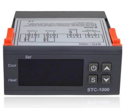
  • Digital closed loop temperature controller
  • Polycarbonate housing.  All electronics relocated outside heated volume, under the printer except Y stepper.
  • Ventilated enclosure system to cool the Y stepper
  • External resettable circuit breaker
  • Housing mounted USB connector
  • Updated to 24 VDC power supply and hot end
  • Custom angled LCD control panel enclosure mounted to the front of the housing
  • Added lighted rocker switches for 110 VAC power, 110 VAC heater, 24 VDC LED lighting, and 24 VDC Aux to front panel
3.  Magnetic HBP and magnetic Glass Build Plate mounts  
  • Simplified, lower (production) cost aluminum mounting frame
  • Hard mounted the bed frame to the Y axis guide block
  • My assumption is that this system will be precise enough to allow change outs of the build plate and glass plate without requiring re-leveling.  I haven't tested that assumption yet.  I just finished machining these mods last night.
4.  Higher resolution leveling system.  
  • Two point leveling.  Rear adjustment remains fixed.  
  • Procedure... 
  • Home Z
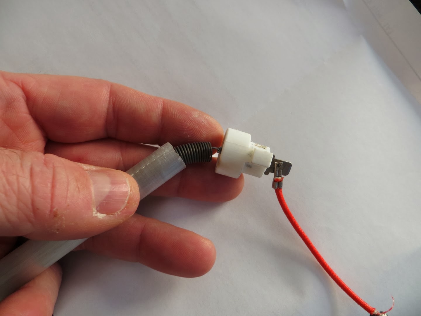
  • The redesigned z offset switch touches the glass bed over the rear mounting point and a light comes on.
  • Move the bed until the left front adjuster is directly under the z switch
  • Adjust left adjuster knob until the light comes on
  • Repeat for the right side
  • Repeat process to double check and fine tune left and right adjustments.
  • Z offset and bed leveling complete
5.  Switched LED lighting system
  • 24 VDC 1000 lumen light strip
  • The on/off witch is mounted on the front of the housing
6.  Updated Extruder mount
  • Simpler, stiffer mount design
Remaining tasks:

1.  Update firmware to allow longer X and Y travel

2.  Auto Z axis offset calibration
  • Finish design, fab and install z switch actuator/switch assy that uses the bed to set the z-offset automatically.
  • Update S3D scripts and possibly firmware as reqd.
3.  Mount Fans
  • Design a blower mount to pass air across the extruder
  • Design a blower mount to pass air past the heat zipper to cool PLA parts
  • Make part blower mount removable and use same mounts to attach a dial indicator to test level and plumb
  • Fab and install blowers/ducts
  • Test

4.  Finish the heater system.  
  • Build prototype that will diffuse the air and heat enough to keep all exposed surfaces under 250F.  Getting closer.
  • Integrate prototype concept into housing which has been scarred to accept the system
  • Test to ensure the Y stepper stays cool enough, the internal temp is controllable within +/-10F without excessive surface temps.
  • Test heat "zipper" that will minimize heat loss around the hot end
  • Test to understand how heated volume affects hot end control, belt tension, and printing characteristics for various filaments.  Especially interested to see if this makes printing larger objects with ABS and Flex filaments less problematic.
5.  Add a desiccated filament feeder box to the housing

Haasen

ungelesen,
20.03.2014, 20:36:5520.03.14
an make...@googlegroups.com
Hi Tony,
I her is an image of the Configuration.h with changes I made to travel further on X-Axis, line 166 & 167 are the once your looking for.

Just open Marlin.pde or Marlin.ino make changes in Configuration.h and upload to Rambo, if everything works save changes.

Michael

Tony Shulthise

ungelesen,
20.03.2014, 22:13:2620.03.14
an make...@googlegroups.com
Thank you VERY much Haasen!!  Did you add longer rails to your M2 also?

Have you made any other firmware changes you would recommend that I add while I'm in there?  Isn't there an advanced config file also?  What kinds of things does it control that config.h doesn't?

Thanks again.  I really appreciate you taking the time to do that.  Let me know if you want any of the files I've put together for this project so far.

Michael Haas

ungelesen,
21.03.2014, 15:12:4721.03.14
an make...@googlegroups.com
Hi Tony,
no I didn't add longer rails, but while building my delta I have to play with Marlin quite a bit.
I changed on my M2 the X travel because I added a cleaning brush see picture. That works really well, the brush comes from my Fortus printer.

 Inline image 2

Cheers,

Michael


--
You received this message because you are subscribed to a topic in the Google Groups "MakerGear - Make Today, Change Tomorrow" group.
To unsubscribe from this topic, visit https://groups.google.com/d/topic/makergear/Jj9kOsaedF0/unsubscribe.
To unsubscribe from this group and all its topics, send an email to makergear+...@googlegroups.com.
For more options, visit https://groups.google.com/d/optout.


--
😊

Tony Shulthise

ungelesen,
21.03.2014, 15:30:5021.03.14
an make...@googlegroups.com
Interesting.  Does the brush help much?

Michael Haas

ungelesen,
21.03.2014, 18:18:5421.03.14
an make...@googlegroups.com
Yes it helps, and it is even more interesting for dual extruder.
It is used to clean the hotend after it is cooled down by 20 -30 degrees before the second hotend starts.

Michael

Tony Shulthise

ungelesen,
22.03.2014, 01:09:3622.03.14
an make...@googlegroups.com
My first printer was a CubeX Duo (junk) but it had dual extruders and it also had a container that it would prime the next extruder into and wipe the extruder before engaging the print with it... sort of like the M2 does a wipe at the start of each print.  It was pretty simple and effective.  It didn't have a brush but it used a spring loaded piece of teflon around 0.1 thick to wipe the extruder nozzle and all the extruder waste was contained in the container behind the wiper.  That one feature worked well.

How well does your dual extruder setup work?  Is it much trouble to get set up and going?  

Michael Haas

ungelesen,
22.03.2014, 07:08:5122.03.14
an make...@googlegroups.com
Hi Tony,
The dual extruder setup works great and there is no setup trouble at all every print comes out just fine. I mean that is what you would expect from a 40k+ machine.
But the flexibility in material is zero and the slicer is garbage.
If the M2 with dual extruder works someday I'm sure the big guys are in trouble my print quality is already better.

Cheers,
Michael

Dusty

ungelesen,
24.03.2014, 13:28:1024.03.14
an make...@googlegroups.com
I did not have as much access to tools as I would like so I came up with a enclosure that you can buy from IKEA. Below is a link to see it.

https://www.youtube.com/watch?v=Ym7PK_hCkrY&list=UU06I1KGddyf1484umnuwRWQ

Regards

jimc

ungelesen,
24.03.2014, 13:38:3224.03.14
an make...@googlegroups.com
thats nice. so in your vid it says you overheated the stepper motors. how hot does it get inside the enclosure? what was happening that tipped you off that the steppers were overheating?

jimc

ungelesen,
24.03.2014, 13:38:5724.03.14
an make...@googlegroups.com
also do you have a part# for the box and door?

Jin Choi

ungelesen,
24.03.2014, 14:15:3624.03.14
an make...@googlegroups.com

Tony Shulthise

ungelesen,
24.03.2014, 16:22:0424.03.14
an make...@googlegroups.com
This kind of idea is better in many ways than the approach I took because this requires only a fraction of the time and money.  A couple suggestions...

1.  For printing up to 100-115 F or so, just move the power supply and electronics boxes outside of the heated enclosure.  You can probably do this without having to lengthen any cables.  You will just need to cut access doors through the enclosure walls to pass the electronics box and cables through.  Slide the M2 right up against the wall so the cables don't need to be lengthened.  If you do have to rewire anything its not nearly as tricky as it seems at first.  Just take pictures of ANYTHING you unplug for later reference.

2.  To print at higher temps (160-190F), which will be required to prevent warping of some ABS parts, you will need to actively cool the steppers.  To do so you could cut a hole and make some kind of tube that leads to the X stepper then just blow outside air onto it.  For the X and extruder steppers, cut the top out and make a channel that goes down to keep the extruder motor cooler.  You have to enclose the Y stepper in a box and run ventilation or water cooling to and from the motor.  Running water cooling to all of the steppers, and possibly to the hot end tube to prevent filament softening, might be easier than modding your box.

3.  Your box is large enough to fit a small space heater and a circulation fan inside for testing after you move the power supply and electronics.  You could probably just set it to whatever temp you want to run at and it will control the temperature for you.  Use a cheap digital thermometer placed near the build volume, viewable through the glass door, to monitor temps.  Just be careful that it doesn't point toward anything flammable.  I'd suggest never running a heater in the box without being in line of sight while the heater is running and have a good fire extinguisher nearby.  A recent Kickstarter was offering a stainless steel enclosure about this size for around $200.  That would probably be much safer.

Post results as you get them.  My first attempt was made of cardboard and you see what its turned into.  You might find yourself getting more and more interested in this idea ;-)

Dusty

ungelesen,
24.03.2014, 19:35:1624.03.14
an make...@googlegroups.com
Below is the parts I bought, DO NOT BUY the BESTÅ VARA case as it is to small, the STUVA case is a bit deeper.

Ikea Parts
BESTÅ VARA Glass door
http://www.ikea.com/us/en/catalog/products/20253874/#/40178586

STUVA Frame, white
http://www.ikea.com/us/en/catalog/products/30128177/

DIODER LED 4-piece light strip set
http://www.ikea.com/us/en/catalog/products/20119418/

Also the kickstarter Tony is talking about is https://www.kickstarter.com/projects/1045344246/maker-kase-universal-printer-cabinet and it was $250 ($300 shipped) and the dimensions are 24” Wide x 22” High x 22” Deep. My case is 22 1/4” Wide x 22 3/4” High x 18 3/4” Deep.

The only motor that is getting hot to the touch is the extruder motor so I am going to print http://www.thingiverse.com/thing:254514, since I do not use the 50mm fan.

I am not planing on adding a heater at the moment.

Tony Shulthise

ungelesen,
24.03.2014, 23:15:4024.03.14
an make...@googlegroups.com
If you don't add a heater I would expect your enclosure to get up to around 100-105 F or higher during printing of a part with the bed at 100F in a 70F room.

The steppers should be okay at that temp.  Some of the other guys in this group would be more qualified to say with more confidence than I can.  Most stepper motors have class B insulation which means they can sustain temperatures up to 90 C without thermal breakdown occurring. This breakdown comes in the forms of insulation and winding failure.  It may be worth adding a temperature probe to them just to verify they don't get over that temp.  I'm not sure that the max temp of the MakerGear steppers is that high or not so check yourself. Remember that the steppers create their own heat so they will run hotter than the ambient air temperature but quite a bit. The good news is that they are cheap so if you have to replace one its not that big of a deal.

I don't know the maximum safe ambient temperature limit for the power supply and control board.  My printer stopped mid print one time when I was using the cardboard enclosure with an ambient temperature of around 105 F.  I assumed at the time that it may have overheated (the board will get hotter than the ambient air just like the steppers do) so I stopped using that enclosure and started working on my current design.  It has not stopped again like that since.  For that reason you may be better safe than sorry and at least move the power supply out and either move the control card out or enclose it and run room temp air through it using an external fan and some kind of ducts or hoses to keep it cool.

I think your enclosure will help with the consistency of your prints but probably may not do much in terms of preventing prints from warping during the build.  However, this thread the guy says his enclosure fixed that problem... https://groups.google.com/forum/?fromgroups#!searchin/makergear/enclosure/makergear/tb5GuBtzKSA/X92aYJG-I_MJ.  Has anyone else heard how that's working out or if he's made anymore changes to his enclosure or printer?

I hope others chime in.  There are a lot of ways to tackle little issues you might face and I'm sure I haven't thought of most of them.  Keep us posted on what you find.  

Here's another related thread...

Tony Shulthise

ungelesen,
07.04.2014, 14:00:4807.04.14
an make...@googlegroups.com
Update... 


I finally got the enclosed M2 up and running again.  Still have lots of tweaking to do but its nice to be printing again.  Here are some observations based on very limited initial testing.  I still have a LOT of work to do to get everything dialed in and debugged but at least its printing again!!...
  1. The longer X, Y and Z travel works great.  I still need to install a larger glass build plate to take advantage of all the extra volume (60% larger build area!)
  2. I printed a 0.3" tall by 6" long part on glass with leftover hairspray at around 75C and it stayed in place without lifting.  Once I get all the little tasks on my growing to-do list finished I'll try to print a very large and tall ABS part to see what happens.
  3. 400 watts gets the inside up to around 85C when using a 100C setting for the heated bed.  I just put a small hair dryer inside set on low.  Its not connected to temperature controller yet but the temperature held very steady once it reached equilibrium.
  4. The Y stepper motor runs about 10C above the surrounding air temp so I'm going to skip enclosing it with outside ventilation for now.  If it fails then its not very expensive to replace it and add the enclosure later.
  5. I love having a lighted power switch and a switch to turn on internal LED lights on the front of the housing
  6. At 85C build volume temperature, the air in the electronics housing has not exceeded 120F.  That should be fine since I have good air circulation going by the Z stepper and the power supply and RaMBO board.

Problems:
  1. My new magnetic bed system doesn't provide any better repeatability than the stock M2 system.  Needs tweaks since I still have to level the bed frequently.
  2. The blocks I made to hold the X and Y axes to the belts need to be made from steel vs. Polycarbonate.  They are very small to maximize travel so they need stronger threads.
  3. The y axis cable track works great but I think it my be catching somewhere very infrequently.  Still troubleshooting that one.
  4. The preloaded high precision Misumi linear guides have the same amount of "slop" as the original M2 guides.  I don't think linear guides are a good choice unless 3 or more on 2 different rails are used.
  5. The enclosed system is just as noisy as the original.  I had hoped it would muffle most of the noise.  The housing muffles the electronics but amplifies other sounds.  The blower in the electronics enclosure is pretty noisy too.  I need to isolate it.  I think I can get the noise down quite a bit with just a little focused effort.
  6. I'm using just one fan for the extruder and parts right now.  For ABS I rotate it so that it blows horizontal across the hot end only.  For PLA I rotate it to about 45 degrees to that it blows on the hot end and the part.  So far that seems to work very well but I eventually want to have independent fans so that will come later.

Bryan Boettcher

ungelesen,
07.04.2014, 14:04:4507.04.14
an make...@googlegroups.com
Very nice work.  It looks great!   except for the pipe clamp along the back but hey cant win 'em all


--
You received this message because you are subscribed to the Google Groups "MakerGear - Make Today, Change Tomorrow" group.
To unsubscribe from this group and stop receiving emails from it, send an email to makergear+...@googlegroups.com.

Tony Shulthise

ungelesen,
07.04.2014, 18:12:0507.04.14
an make...@googlegroups.com
You mean you don't like my custom designed clamp filament holder system !?!?!?  ...That really hurts, Bryan ;-)

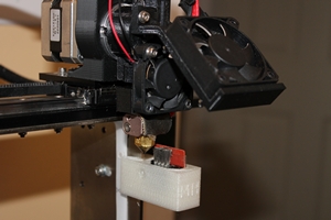
The clamp will be replaced with a desiccated box to hold filament soon.  Its been so long since I've printed anything I just wanted to make sure I could ;-)  Its coming together one little step at a time...  Only 273 more steps to go...

Robert Silvers

ungelesen,
07.04.2014, 20:23:2007.04.14
an make...@googlegroups.com

I have my own laser cutter, so I could make a Tony-style enclosure. I even have sheets of acrylic. That being said, I know not to make stuff that I can buy, so I like the Dusty idea, and just ordered the Ikea stuff. I will laser-cut wire-holes in it - or maybe even a fan to cool it when it goes above, perhaps, 100F.

A few questions - will the STUVA enclosure allow the printer to face forward?

Can you really put an Ikea door on each side? It would seem that would destroy the structural integrity of the box to have two sides with no support. I guess I could use glue and make it stronger. But if the STUVA is large enough with one door, please let me know.

Dusty - if your stepper over-heats, you can just adjust the RAMBO to lower the current to it and it will run cooler.

Dusty

ungelesen,
07.04.2014, 22:44:3307.04.14
an make...@googlegroups.com
The STUVA enclosure will not allow the printer to face forward. It would need a few more inches.

I do believe you can put a door on both side and yes that would hurt the structural integrity of the box, I would suggest not putting 100lb on top of your enclosure.

I have not had the inspiration to work on my printer so nothing really has changed yet. But when I worked on my prusa I did mess with the stepper controller to cool them, I have not look into it on the RAMBO board yet. That is a good idea.

Tony Shulthise

ungelesen,
08.04.2014, 15:34:1008.04.14
an make...@googlegroups.com
When I was running mine around 80C the Y stepper motor was only at 90C while printing.  That surprised me.  Not all steppers are rated for the same max temperature but from the little I've been able to find, generic steppers should be good to around 100C case temperature.  With that said, my GUESS is that you shouldn't have to worry about your stepper motors for temps under 80C or so.  

The problem areas are still:
1.  You will need to keep your control card, power supply(s) cool.  However, keeping them cool is MUCH easier than isolating the motors.  Either relocate the control care outside of the heated enclosure -or- build a ventilated enclosure around the control card to allow cooling via ambient air.
2.  A much more difficult problem to solve is keeping the filament drive and hot end cool so the filament does not soften and jam between the extruder and the nozzle.  One possible solution for that is to just raise the M2 up and let the X axis poke out of a slot in the top of the enclosure.  Its not that difficult to make a Kapton tap "zipper" that keeps plenty of heat in.
Allen antworten
Antwort an Autor
Weiterleiten
0 neue Nachrichten