24V M2 updated VIKI Firmware

Curtis Menard
I forked Jin's Marlin firmware and have been using it and modifying it since I purchased my printer. There have been a number of questions about which firmware to use so I thought I'd put mine out here.
Features:
* M108 is removed and replaced by automatic control of the extruder/electronics 40mm fans based on extruder temperature. Currently the 40mm fans will turn on/off at 35C.
* Full VIKI LCD with microSD card support.
* "MakerGear M2" will be displayed in VIKI as the printer name.
* I'm using a 24v 50mm fan and the firmware is currently configured for that. **NOTE** If you still have the 12v 50mm fan you will need to edit the Configuration.h and change line 623 to //#define M2_24v_50mm_Fan. This will run the fan at a max setting of 155 and a default speed of 127 if just an M106 command is issued. **NOTE**
* M106 will turn the 50mm fan on and M107 will turn it off. You can still send M106 Sxx to change the fan speed or even M106 S0 to turn it off.
In the Arduino IDE if you get a compilation error looking for LiquidTWI2, go to Sketch/Import Library/Add Library and browse within the downloaded firmware to Marlin\ArduinoAddons\Arduino_1.x.x\libraries\LiquidTWI2 and add the library. The firmware should compile and flash to the RAMBo without further error.
Link:
https://github.com/cmenard/Marlin/archive/MakerGearM2.zip
Thanks,
Curtis

Jin Choi

WayneN
WayneN
Curtis Menard
It's not missing, just moved. Search the Configuration_adv.h for DIGIPOT_MOTOR_CURRENT. You'll see that the same current settings are there.
Sent from my Nexus 5
--
You received this message because you are subscribed to the Google Groups "MakerGear - Make Today, Change Tomorrow" group.
To unsubscribe from this group and stop receiving emails from it, send an email to makergear+...@googlegroups.com.
For more options, visit https://groups.google.com/d/optout.
WayneN
WayneN
Curtis Menard
Can you start the fan with the slider in creator? Or by sending a M106 S255?
WayneN
Jin Choi
Curtis Menard
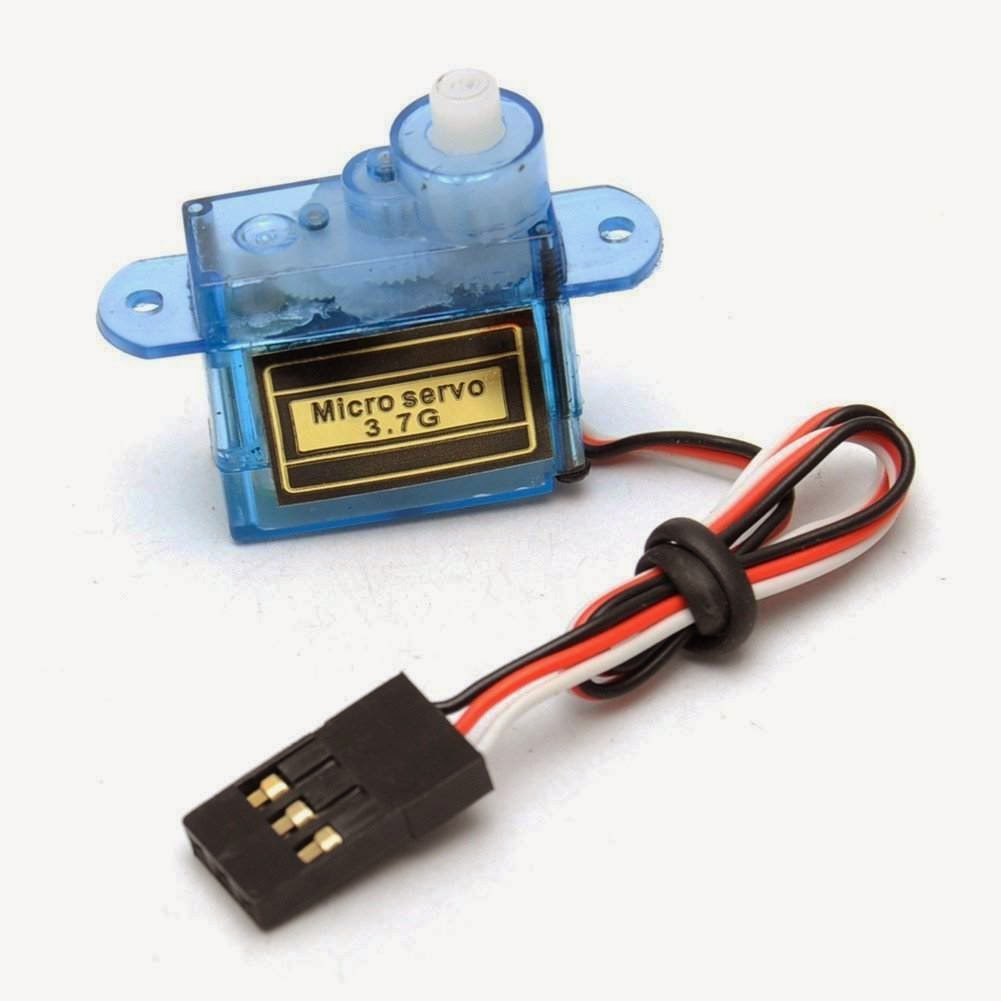
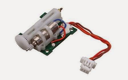
There has been much updated with this and I plan to try a servo activated mechanism similar.
Jin Choi
Curtis Menard

Tony Shulthise
Jin Choi
Tony Shulthise
Jin Choi
On Sunday, March 16, 2014 4:14:55 PM UTC-4, Tony Shulthise wrote:
Are there PWM outputs on RAMBo that could be used to easily control hobby servos?
Curtis Menard
What about adding the pins to MX EXT or there's also PWM EXT. I would think that either could run a servo.
Sent from my Nexus 5
--
Curtis Menard
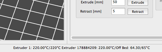
New gcodes:
// G10 - retract filament according to settings of M207
// G11 - retract recover filament according to settings of M208
// M207 - set retract length S[positive mm] F[feedrate mm/min] Z[additional zlift/hop], stays in mm regardless of M200 setting
// M208 - set recover=unretract length S[positive mm surplus to the M207 S*] F[feedrate mm/sec]
// M209 - S<1=true/0=false> enable automatic retract detect if the slicer did not support G10/11: every normal extrude-only move will be classified as retract depending on the direction.
Here's the notes from my git commit:
Firmware retraction can now be enabled via the Retraction LCD menu. It
can also be enabled by issuing a M209 S1 command. To disable issue M209
S0.
I've corrected the LCD display issue and the feed rates are now in
mm/sec with a maximum value of 100 mm/sec.
For this feature to work your slicer must have retraction enabled and
some value for the amount of retraction. When the firmware sees a
retraction event from the slicer the settings will be replaced with
those in the firmware.
On the fly changes to retraction can be made via the LCD. They can also
be changed with gcode as below:
M207 - set retract length S[positive mm] F[feedrate mm/sec] Z[additional
zlift/hop]
M208 - set retract recover length S[positive mm surplus to the M207 S*]
F[feedrate mm/sec]

Ed Nisley
The table I pulled together a year ago may be helpful to avoid collisions, but it's not a complete list of all the CNC dialects out there.
Recycling G10 for retraction probably won't end well...
Curtis Menard
You will however need to move two wires on the board for this work properly. The pin moves are so that other LCD's wouldn't need changes in the firmware to function with Rambo. Trying to keep things inline with upstream Marlin changes.
Differing from MakerGear's instructions:
Yellow wire from EXT2 pin 15 should land on EXT2 pin 14. Black wire
from EXT2 pin 13 should land on EXT2 pin 20.
The latest version can be grabbed from here:
https://github.com/cmenard/Marlin/archive/MakerGearM2.zip

Dale Reed
On Wednesday, March 19, 2014 10:07:40 PM UTC-4, Curtis Menard wrote:
For those that like to try new stuff, this firmware package has.....t
Jin Choi
Curtis Menard
To fix the compile error you can do the following:
In the Arduino IDE if you get a compilation error looking for LiquidTWI2, go to Sketch/Import Library/Add Library and browse within the downloaded firmware to Marlin\ArduinoAddons\Arduino_1.x.x\libraries\LiquidTWI2 and add the library. The firmware should compile and flash to the RAMBo without further error.
At this point your SDCard reader is probably not going to work. You'll need to uncomment line 492 in Configuration.h like this <b>#define SDSUPPORT</b> to enable it again.
Dale Reed

Jamie Frost
Works like a charm, does what I need it to; The rambo having a very cryptic pinout is difficult to figure out how to rewire the sd pins but now I have that figured out it's a blast! Just need to tweak my z-motor torque (keeps slipping and dropping down while trying to move upward) up a bit.
Thanks again!
[virtual beer]
WayneN
WayneN
WayneN
On Sunday, March 30, 2014 8:12:06 AM UTC-4, WayneN wrote:
Got it- I wasn't getting a good connection on black pin 20.Another question though- how can I slow down the extrusion speed in VIKI? Its too fast for filament changes without pausing.
WayneN

John Barnhardt
John Barnhardt