Automatic tramming/leveling on a Replicator 2X

Scottbee
The tramming/leveling routine can be run as a stand-alone X3G that we just put on my SD card, but in my production environment I prefer to have it as part of the start.gcode for every print. The printer comes to operating temperature (so there isn't any hard ABS on the nozzle tip(s).. and so that the unit has thermally stabilized), performs the tram, and then immediately starts printing. It adds ~10 seconds to every print.
As a caveat and reminder, this system will not compensate for warped or otherwise deformed build surfaces. It will take three points on the build surface, call that a plane, and set that plane parallel to the XY motion plane. If there are mountains and valleys in-between those three points the system has no way of knowing.
As I mentioned at the beginning of this diatribe, I have two machines with this system currently installed, and there will hopefully be a third in the next week or so. To-date the results have been quite, quite promising... and the first layer repeatability has been as good if not better than what I can achieve with a methodical traditional manual approach.
Enjoy!

bigjosh
...can't wait to see how you approached the filament width issue.

Jimc
Scottbee
Scottbee

Ryan Carlyle
The really great thing about this design is that it physically moves the bed to a trammed position using the Z motor and nozzles. That eliminates a lot of the issues with repeatability that height-sensing switches have. (Switches don't always switch at the same distance/travel.) The only position-sensing switch here is the Z axis limit switch, and tram gap positioning is relative off of that... So there's no error introduced from switch travel variation.
As long as your nozzles are even and build plate is flat, this is pretty bullet-proof.

Pomme
Do you have any plans to release your design? kitbom.com, thingiverse.com or anything similar? I'm very curious about the "gimbaling pins" and the three corresponding pin clamps that you used.
I wonder also if your support bended with the pressure required to push the surface in position and if you compensate for it in the gcode?
Thanks for sharing this idea. You are a talented engineer.

Brandon Andrzejewski
Scottbee
Scottbee

mkapras
Brandon Andrzejewski

Jetguy
Jetguy
On Tuesday, April 15, 2014 2:49:39 PM UTC-4, Brandon Andrzejewski wrote:
Jetguy
Scottbee

Normand
Do you think it would be possible to trigger a release mechanism when the support hit the bottom of the printer in Z? That would spare the need for a DC motor.
You sparked something there. Thanks
Jetguy
Scottbee
Brandon Andrzejewski
You totally missed the operation.
Ryan Carlyle
On Tuesday, April 15, 2014 2:28:06 PM UTC-5, Jetguy wrote:

Randy_y
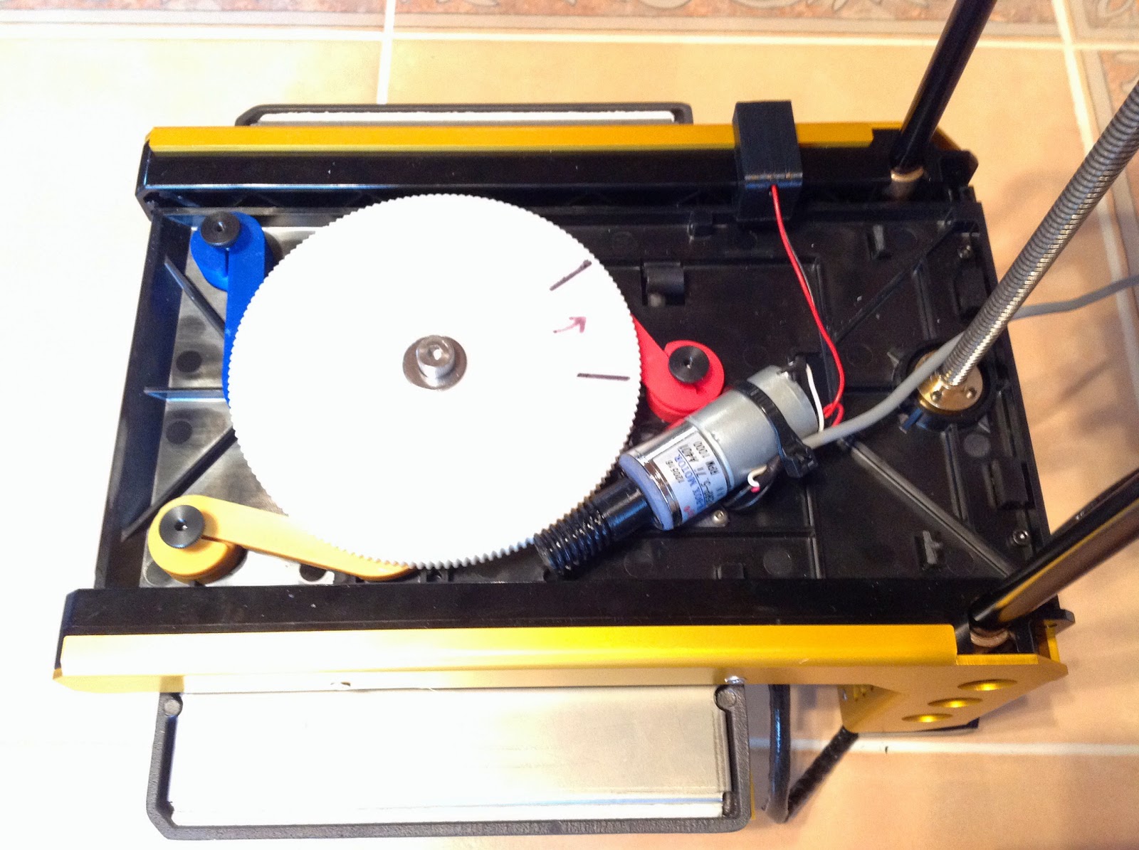
Replacing the three leveling jack-screws are three "gimbaling pins", and there are three corresponding pin clamps built into the span/spreader plate. These pin clamps can lock the gimbal pins at an infinitely variable Z elevation.
Scottbee

Justin Blake
That really is a beautiful, elegant solution. Well done. I hope you release the designs at some point, I would love to add one of these to my machine.

Bas van Deursen

Fri Rider
Would you share the files for the components?
Thanks
On Monday, April 14, 2014 9:38:38 PM UTC-4, Scottbee wrote:
Scottbee

Bryan Casey
Ryan Carlyle
Scottbee
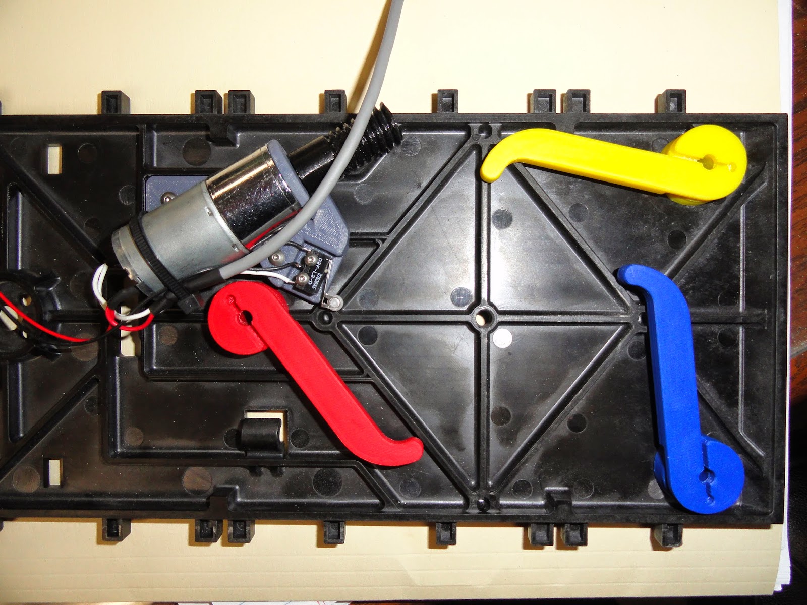
The gear-cam is simpler than one might think... but it's also a bit of a bear to print. You only need to release one clamp at a time to do the tramming, so there is only one "inverse lobe" location... with a lot of dwell.

Once you get your head wrapped around the way it works, you'll probably just say "duh".

Robert Quattlebaum
Scottbee
On Thursday, April 17, 2014 12:53:23 PM UTC-5, Robert Quattlebaum wrote:
I'm almost afraid to ask, but... Do you intend to patent this mechanism? And if you do decide to patent it (and the patent is granted), would you consider giving a license to people who build their own for personal use to do so royalty free?I know that if I built one and it worked well I would happily "buy you a beer" and then some (It's a great design!). I'd be quite disappointed if I wasn't allowed to build one of these marvelous devices myself one day.Again, this is a great idea, and thanks for sharing how it works with everyone!
Robert Quattlebaum
> Don't be afraid to ask..... but I should probably be afraid to answer!
> I'm an inventor by trade and profession. It's how I make my living, it's how I feed my family. And therefore my normal workflow involves invention disclosures, provisional patent applications, and patents. This invention and embodiment was no exception.
I have no problem with you patenting what appears to me to be a novel and inventive hardware mechanism.
> I didn't go after IP protection to preclude the individual enthusiast from utilizing the technology to enhance their own systems. If a person wants to expend time and energy to get this type of system to work on their machine I certainly won't get in their way... and will (on a limited basis due to my own time constraints) make attempts to be helpful (but it's a little early in the program for that).
> The IP protection is basically to stop some enterprise from coming in and making the invention their own, generating revenue and profit without some form of appropriate acknowledgement and attribution to the inventor. We inventors usually have a substantial investment in our designs... both time and money.... and just like anybody else we like to see a return on that investment.
>
> That's not always a popular position and methodology in the "open source" world.......
Again, great job, and I look forward to hearing more about it once you have finished polishing it!
-- Robert

Bernard Kerckenaere
Fri,I'm not trying to be a jerk here (I don't have to try, it comes naturally)... but I don't consider my implementation to be ready for public consumption yet. I'm just a bump beyond Alpha testing and am just moving into Beta.There are hardware refinements that I am currently working on, and the software side is being pondered and refined as well.I'll discuss the implementation all day, but I don't want to release any source yet. I prefer to slow-roll this a bit.
Any updates on your current status?
I'm about to put together my interpretation of an i3, and would love to put a system like this in it (I really don't like the more common probe method of compensating for an unlevel bed through software.) I was thinking of lasercutting the components out of acrylic, instead of printing them, it doesn't look like this would be a problem, apart from needing to bond together two layers to form the main gear?
Can you tell me what the height of the space is between the mounting plate and top plate with this mechanism sandwiched between them? Then I can at least take this into account while I'm designing where to put the Z axis endstop.
Nice work!
Scottbee

Aisflou .
Any news on this subject?
Im very excited with this bed leveling tecnique!!