Replicator 1 owners looking for a 5 volt regulator mod here is the best answer!!

Jetguy
P/N: JC030A1-29M
Input: 18-36V DC
Output: 5V DC 6A
Specifications/Features: Sealed DC/DC converter module. .1% line/l.2%oad reg. 150mV P/P ripple, short circuit protected, remote sense, remote On/Off (Low-On/High-Off),500V isolation. UL,CSA, VDE Listed.
L: 2.4" W: 2.28" H: .5" WT: .2

Clinton Hoines
Would something like this work ok? Since I have 2 bots to mod and can find use for the other pieces I'm sure. Just not sure the 2A-3A output is high enough rating?
http://www.ebay.com/itm/10-pcs-DC-DC-LM2596-Step-Down-Adjustable-Converter-Power-Supply-Module1-3V-35V-/130984316514?pt=LH_DefaultDomain_0&hash=item1e7f460e62
Jetguy
Jetguy
Clinton Hoines
Would it be as simple as replacing the cap with the higher value?
Thanks for all your help on this for all the rep1 guys, really appreciate it.:)

Dan Newman
On 19 Oct 2013 , at 8:31 AM, Clinton Hoines wrote:
> Great option for guys in the US, looks like shipping to Canada and even
> ordering would be a pain and they don't ship anywhere else.
>
> Would something like this work ok? Since I have 2 bots to mod and can find
> use for the other pieces I'm sure. Just not sure the 2A-3A output is high
> enough rating?
on it do not have the same layout/assignment as the 3 pins on the 5V linear
regulator! This part is nowhere near as cheap at $22 US, but the TI rep
sent me a couple as samples.
Texas Instruments PT78HT200 Series DC/DC Switching Regulator
I have it mounted by some (very good) double sided tape along one narrow side
of the device to the inside wooden wall of my Rep 1. I didn't bother dead bugging
it right atop the motherboard.
Personally, I prefer the lower current ones as they'll operate more
efficiently but that's just personal preference on my part.
Dan

f4ichuck
Thanks,
-Chuck
Jetguy


Chuck Joga
Sent from my iPad
--
You received this message because you are subscribed to a topic in the Google Groups "MakerBot Operators" group.
To unsubscribe from this topic, visit https://groups.google.com/d/topic/makerbot/Qpzv6f8wJPs/unsubscribe.
To unsubscribe from this group and all its topics, send an email to makerbot+u...@googlegroups.com.
For more options, visit https://groups.google.com/groups/opt_out.

Ticko

Terence Ang
Ticko
Den lördagen den 19:e oktober 2013 kl. 04:42:08 UTC+2 skrev Jetguy:
Jetguy

Warren Delarme

Jamesarm97
Warren Delarme
Clinton Hoines
Here you go, just did mine a little while ago real easy thanks to Jetguy. :)
Just match the pin order in the pic with the spec sheet. You don't have to desolder the regulator from the board just cut the pins.


Warren Delarme
Warren Delarme

sjlane7160
- Stephen Lane wrote:
- I did mine last night, I used the parts below
- RS Stock No. 739-8290
- Manufacturer Recom
- Mfr. Part No. R-78C5.0-1.0
I also installed the 3.3v fuse as per the pics thats
- RS Stock No. 517-6641
- Manufacturer TE Connectivity
- Mfr. Part No. RXEF065
- I used Jetguys pics as previously linked to & its just completed a 4 hour print as a test
- by the by while you've got the bottom off it makes sense to lube the inside fan (peel the lable up & drop a spot of oil in the bearing) or replace it if you are that way inclined there are some suggestions that
- putting a hole in the side of the bot in line with the internal fan (& installing a fan finger sheild) & blocking the holes in the bottom of the bot while you are at it will help - cool room air not warm chamber air
- blowing over the Mighty board there are is at least one Thingiverse project on this so have a search
Regards
Stephen
Jetguy

Fastrack
Jetguy

Chris Fastie

It has nine pins. Any advice on how to wire this?
Jetguy
Chris Fastie

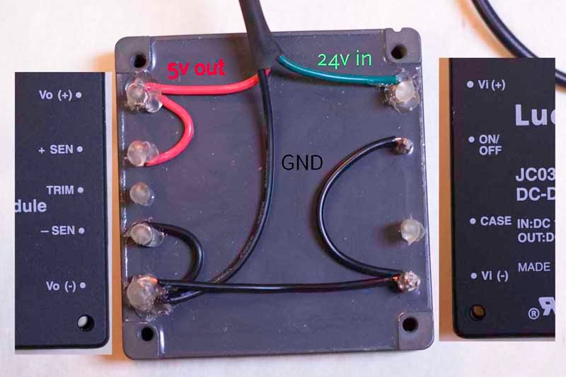
1. Connect pin Vo(+) to pin +SEN (orange line).
2. Connect pin Vo(-) to pin -SEN (orange line).
3. Snip off the old regulator leaving the leads attached to the board.
4. Connect the three leads left from the old regulator:
- Connect GRD to ____________?
- Connect 5V out to ___________?
- Connect 24V in to ___________?
Use long wires so the new huge regulator can be placed somewhere out of the way.
Anything else?
Fastrack
Ben
Jetguy
- Connect GRD to ____________?
- Connect 5V out to ___________?

Chris Fastie

Actually Fastrack said GND goes to Vi- OR Vo- and Jetguy said Vi- AND Vo-.
Should I go with all red and orange connections?
Jetguy
benjami...@gmail.com
Sent from my iPad
Chris Fastie

Joseph Chiu
You are apparently not getting the 5 volts output from the converter. The first step is to find out why not. The fan is powered by the 24 volt side. Can you take some pics of your current set up?
--
You received this message because you are subscribed to the Google Groups "MakerBot Operators" group.
To unsubscribe from this group and stop receiving emails from it, send an email to makerbot+u...@googlegroups.com.
Jetguy
Jetguy
Remote On/Off
(VI = 0 V to 36 V; open collector or
equivalent compatible; signal referenced to
VI(–) terminal. See Figure 22 and Feature
Descriptions.)
JC030x1-M Negative Logic
Logic Low—Module On
Logic High—Module Off
Jetguy
Sorry for any grief this has caused you and we'll work through this a document for anyone else using the module.
Chris Fastie
Chris Fastie
Jetguy
Chris Fastie

Jetguy
Chris Fastie

Ben Withers
--

funBart
Jetguy
funBart
Ben Withers
Clinton Hoines
Dan Newman
> I was about to start checking continuity and then determine if the new
> module is getting 24 volts, when I noticed a big scratch through a trace
> right next to the 24 volt in lead for the old module. This trace is
> scratched completely through and there is no continuity across it. I was a
> little surprised that I could have been so sloppy, and a lot more surprised
> that I could have done that without realizing it. So I started to fix the
> break with solder, but then I noticed that the scratch is present in a
> photo I took of the old regulator before I even touched the board.
>
> It looks like someone went to some effort to sever that trace. Is this cut
> trace supposed to be there? Is it present on other Rep 1s? Should I NOT fix
> this?
of 24V for Vin. That regulator can handle 24V as input but has to dissipate
the difference between 24V and 3.3V as heat. It needs better heat sinking
to do that reliably and since a ready source of 5V was available, MBI fixed
the design error after the fact.
Dan
Chris Fastie

Dan Newman
> I'd be scared of an external adapter, as unless it's an expensive one they
> don't output exactly 5V.
chips won't care (too much) about the fluctuations, the stepper driver chips may as
they are doing current measurements. And their reference voltages may vary as well.
Dan
funBart
On Wednesday, 15 January 2014 17:30:50 UTC+1, Fastrack wrote:
I'd be scared of an external adapter, as unless it's an expensive one they don't output exactly 5V. Plus unplugging like Jetguy suggested is a bit of an issue :)
Jetguy

Gary Crowell
--
You received this message because you are subscribed to the Google Groups "MakerBot Operators" group.
To unsubscribe from this group and stop receiving emails from it, send an email to makerbot+u...@googlegroups.com.
Gary Crowell
Gary Crowell
Joseph Chiu
Well, it did start out as an open source project by people that were inventing everything from scratch.. ;-)
Dan Newman
> Well, it did start out as an open source project by people that were
> inventing everything from scratch.. ;-)
a summer internship for an Electrical Engineer starting his final
year of college. That's great and was assuredly a valuable experience
for the intern. However, a company providing such an internship needs
to provide mentoring and oversight by a veteran of the field. That
doesn't seem to have been the case.
Dan
Jetguy
Jetguy

Jetguy
Gary Crowell
- minimum step low duration = 1.9us
- minimum step hi duration = 1.9us
- minimum setup time dir change to step rising = 650ns
- minimum hold time dir after step rising = 650ns
Chris Fastie
Dan Newman
> I think Gary and Jetguy are correct that my connection from the new module
> to the 5 volt circuit on the board (middle lead on the old module) was bad.
> I confirmed connectivity through the green wire to the 3.3 v regulator, but
> not necessarily to the board.
>
> When I clipped off the leads to the old regulator, the connections to the
> board were stressed and weakened. After soldering new wires to the clipped
> leads, I covered it all in hot glue to protect the fragile connections. So
> I couldn't really access the connections to the board anymore. I never
> pulled the old regulator off, and it got involved in the hot glue.
>
> So I just removed those three connections. Unfortunately, everything came
> up with the hot glue, so there is not much to solder to anymore. If I
> remove the old regulator, connecting 5v out will be easy.
tab is Vout (+5V). You can see if the tab connects to the 5V rail and if
so, solder your new incoming 5V to the tab.
> How do I remove the old regulator? Just yank?
up without removing copper from that side of the board. Not a good idea.
> Can the little green wire to the 3.3 v regulator also connect to the big
> pad under the old regulator?.
> Is there another good place to connect to 24v in?
(I have CNC-style 14.6A @ 24V PSU's on my Replicators.)
> Is there another good place to connect to ground?
housing. (I have a good soldering iron and I turned it's temp up to the
675F neighborhood.)
> Is there another good place to connect to 5v in so I don't have to remove
> the old regulator?
old regulator's Vout leg/pin. (I recall that as being the center leg/pin
on the 5V regulator, but check the data sheet.) [I used a very tiny
DC/DC converter for my 5V. It's dead bugged to the inside of the wooden
case with a tiny bit of double sided tape.]
Dan
Jetguy
Dan Newman
liberal use of soldering flux (e.g., flux pen). That case connects to the
board's ground at four solder pads. You could solder to at least
two of those pads. At the end of the day, you want the ground return
path to have as little resistance as possible and hence sufficient
gauge wire with good total contact area with the board.
Dan
Jetguy
Dan Newman
> Also, soldering to the case of the power input jack is probably not the
> best place to pick up ground. The reason is, understand what happens if
> the ground comes loose while powered.
to do it the way I mentioned (using the case). Mine ain't coming off anytime
soon, but I had tools up to the task.
Dan
Jetguy
Chris Fastie
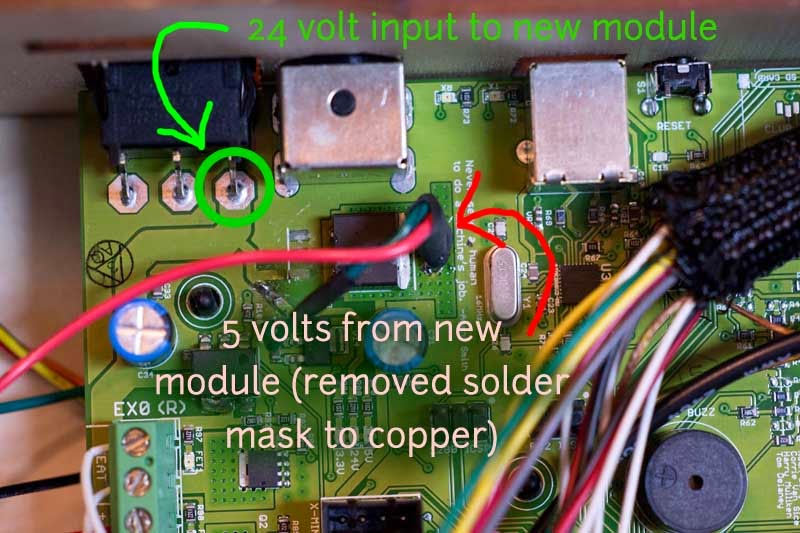
- 5v wire to the stub of the middle pin of the old regulator (along with the little green wire to the 3.3 v regulator).
- GND wire to the outside surface of the power jack housing (with careful preparation, etc).
- 24 v wire: I don't see the "two contacts from the power jack housing" that Dan mentioned. Is Dan's board different, or are they on the other side of the board? I have not yet seen the other side of the board. Are there other options for the 24 v wire?
Dan Newman
> - 24 v wire: I don't see the "two contacts from the power jack housing"
> of the board? I have not yet seen the other side of the board. Are there
> other options for the 24 v wire?
a square which are the grounds from the case. And two to the inside
which are the 24V. But, I could be wrong -- was about a year ago
when I modified a couple of boards.
Dan
Dan Newman
> - 24 v wire: I don't see the "two contacts from the power jack housing"
> of the board? I have not yet seen the other side of the board. Are there
> other options for the 24 v wire?
Dan
Jamesarm97
Gary Crowell
Chris Fastie

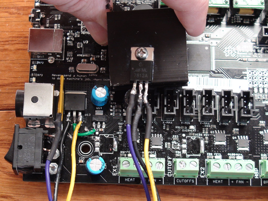
There is not much left of the stub on the old regulator to solder the 5 volt wire (top photo), but it can be done. Are there any other options for the 5 volt wire (the third leg on the switch?)?
As far as I know I haven't broken anything else in a couple of hours, so I am feeling good.
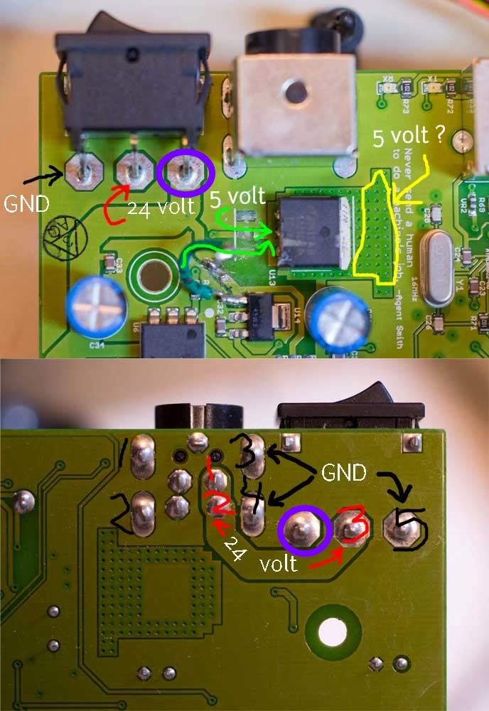
Dan Newman
> It looks like the other side of the board has good places to connect the
> GND wire and the 24 volt wire from the new module (lower photo). What do
> you think about instead using the legs on the power switch on the top of
> the board (upper photo)?
because I didn't want to bother pulling the board. (Mind you, that power switch
is not properly rated for the currents involved, but that's another story.)
> There is not much left of the stub on the old regulator to solder the 5
> volt wire (top photo), but it can be done. Are there any other options for
> the 5 volt wire (the third leg on the switch?)?
I understand the difficulty you're looking at. Also, the darn thing
doubles as a small heat dissipator and so it can be a pain to solder
some times.
3rd leg on the switch? Did you mean 3rd leg on the regulator?
Dan
Dan Newman
the copper clad and solder the 5V to it. Clearly that whole region is good: I can see
it flowing over to the smoothing capacitor above the 3v3 regulator.
Dan
Chris Fastie
3rd leg on the switch? Did you mean 3rd leg on the regulator?

Dan Newman
>
>>
>> 3rd leg on the switch? Did you mean 3rd leg on the regulator?
>
>
> I meant the third leg on the power switch, but I guess it is not 5v.
goes in the common contact and comes out one pole when the switch is in
one position and out the other pole when the switch is in the other position.
In your diagram, you showed one pole being tied to ground. If that's indeed
the case, that would seem to be a mistake and if the switch mechanically fails
may send 24V direct to ground. If you don't use a pole, you leave it alone.
That things work indicate that they are feeding the 24V into a pole and then
drawing it out the common contact. That then has the effect of seeing +24V
when the switch is in one position and seeing "ground" when the switch is
in the other position. Maybe they wanted that for real? Odd, since these
cheap mechanical rocker switches can and do break in such a way that the
metal contacting plate can close both poles at once
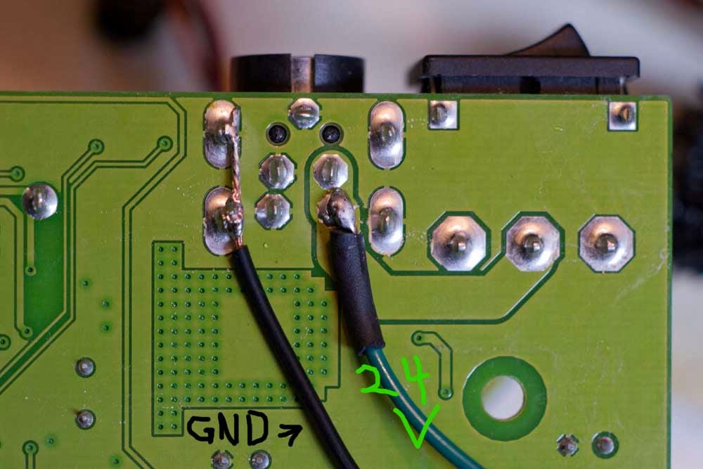
> I already have the board out, so it is easy to solder to the other side.
> Which of those soldered contacts under the switch and power jack would you
> choose for GND and 24v (I numbered them in the photo below)? Should I use
> more than one for GND?
to the board: that's the actual ground presentation. You can send the 24V in
to the contacts from the power inlet or to the rocker switch pin to which it
feeds.
>
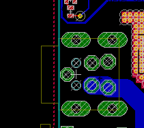
> Do you think anywhere in the yellow area in the photo there is copper under
> the solder mask I can connect the 5 volt wire to?
board is one of removing copper. That whole area is copper there minus the
drill hits.
Dan
Joseph Chiu
Chris Fastie
- The LCD display is lit with blocks but no characters.
- All three green LEDs are lit (3.3v, 5v, 24v).
- A red "Overheat" LED is lit. (Yikes)


Dan Newman
> Well that was fun, but it didn't work. Photos of the connections I made are
> below.
>
> As soon as the Replicator is plugged in (power switch off):
>
>
That means the module has powered up and received no instructions. Shortly
after the microprocessor starts, it sends a "clear display" command to it.
> - All three green LEDs are lit (3.3v, 5v, 24v).
Could be good.
> - A red "Overheat" LED is lit. (Yikes)
There's no functional overheat LED. I think that may be one of the
debugging LEDs. There's certainly no code in the microprocessor
to turn on an "overheat" LED.
> When the power switch is turned on, the fan starts and the green LEDs for
> each of the five stepper motors are lit. No sound, no chamber LEDs.
would clear after a second or two and the default color choice would be sent
to the RGB LEDs. I'm surprised the chamber LEDs aren't red -- that is their
normal power-up color which sticks briefly until the microprocessor boots
enough to send a different color choice. That you see no color on them suggests
that the logic chips for it may not be functioning either.
You might want to find a 5V test point on the board and see if you see 5V
between it and ground. However, as you've been told, it's not unusual for
the blown 5V regulator to take out some of the logic chips.
Dan
Jamesarm97
Chris Fastie
Joseph Chiu
Joseph Chiu
Chris Fastie
the one on the switched side -- the leg closest to the power connector.

Joseph Chiu
--
Chris Fastie
Joseph Chiu
Yes, with the power switch off, the center and right legs are not connected (but center and left are). With the power switch on, the center and right legs are connected. So I will solder the 24v wire to the right leg.
--
Ben Withers
Yes, with the power switch off, the center and right legs are not connected (but center and left are). With the power switch on, the center and right legs are connected. So I will solder the 24v wire to the right leg.
--
You received this message because you are subscribed to a topic in the Google Groups "MakerBot Operators" group.
To unsubscribe from this topic, visit https://groups.google.com/d/topic/makerbot/Qpzv6f8wJPs/unsubscribe.
To unsubscribe from this group and all its topics, send an email to makerbot+u...@googlegroups.com.
Dan Newman
> 5... 4... 3... 2... 1...
Hopefully not the Firefly (Pod 3 and 6, depending upon the episode).
FAB.
Chris Fastie

Fozzie
Chris Fastie
MISSION DEBRIEFING
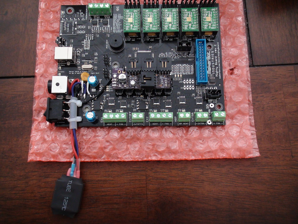
My newly regulated Replicator has made several successful prints, so it looks like I am out of the woods. Here is a summary of my foibles in case anyone else wants to try this upgrade.
- Early trouble: The first thing I did got me into trouble. I
snipped off the three pins of the old regulator with good wire snips, and this torqued
their soldered connections to the copper traces in the PCB. By the time I had all three new wires soldered
to the severed pins, the connections to the traces were flimsy at best.
Apparently the 5 volt (center) connection broke in the process, and this
cascaded into later malfunction and confusion. I am not sure how to avoid this
problem. Grind the old pins through with
Dremel? Hot glue the soldered connections before I start cutting?
- RTFM: The new Lucent regulator module has nine pins, not three like the original. It has a 20
page spec sheet which you have to consult in order to make the proper
connections. I have a PhD in science,
but no EE training, so that spec sheet is completely uninterpretable to me. Fortunately, folks on this list were willing
to take the time to read the sheet and translate for me. Thank you. However, the
first time I hooked up the new module and plugged in the Replicator, the module
was wired incorrectly. It turns out that no damage was done, but it took a
couple of hard days to confirm that. I should have tested the output of the
module before I sent it to the Mightyboard.
- Plan B: When the connections to the PCB were
suspect, I removed them and started over. The contacts for the original regulator were no longer
suitable places to make good connections, so I had to find alternate places to
connect to a 24 volt source, a 5 volt input to the board, and ground. That’s
easy if you know the board or know how to read the published schematic. Again, I thank folks on this forum who walked
me through this. It was revealing to watch how your posts got progressively
more explicit as you realized who you were dealing with.
- An unfortunate event: After removing the board to solder new
connections underneath, I replaced it temporarily to test again. The test
failed, and it took a day to learn that the reason was that the reset button was
being partly depressed because it was not aligned with its access hole in the plywood
case. The symptoms caused by this unlikely occurrence mimicked the failure of
logic components and convinced me, and I think others, that the worst had happened.
I was stunned when the machine booted normally; I was not expecting that. I was and still am very grateful to those on the forum who helped make this happen.
Below are images of the connections that seem to work. Give it a try.
Chris

Chuck Joga
-Chuck
--
You received this message because you are subscribed to a topic in the Google Groups "MakerBot Operators" group.
To unsubscribe from this topic, visit https://groups.google.com/d/topic/makerbot/Qpzv6f8wJPs/unsubscribe.
To unsubscribe from this group and all its topics, send an email to makerbot+u...@googlegroups.com.

Fredini

Dan Beavers
Dan B

kenneth w grigsby
On Saturday, October 19, 2013 10:58:39 AM UTC-5, Jetguy wrote:
BTW, Gary's mod used 500mA regulators so we are well above the minimum current rating.In my own testing, worst case never ever exceed 300mA load even with it powering the 3.3 volt regulator powering a Toshiba Flash air SD card.So for sure, we know the worst case scenario load and we are magnitudes above it.
On Saturday, October 19, 2013 11:55:47 AM UTC-4, Jetguy wrote:I have the same modules but haven't tried or tested them much. Personally I think they would work fine, but I haven't tested it.One note, I wrote and extensive review on the exact board from Amazon and they didn't 100% follow the suggested circuit. The output cap is correct but the input cap is a little on the light side for values. I believe it should be 680uF but it's only 220uF just like the output cap.I don't know what EMI, RFI, and ripple values are out of it given the component choices.I'm not saying it won't work, I'm just trying to share my knowledge after reading the data sheet which is very good and explains how chosen component values should be determined.
On Saturday, October 19, 2013 11:31:48 AM UTC-4, Clinton Hoines wrote:Great option for guys in the US, looks like shipping to Canada and even ordering would be a pain and they don't ship anywhere else.
Would something like this work ok? Since I have 2 bots to mod and can find use for the other pieces I'm sure. Just not sure the 2A-3A output is high enough rating?
http://www.ebay.com/itm/10-pcs-DC-DC-LM2596-Step-Down-Adjustable-Converter-Power-Supply-Module1-3V-35V-/130984316514?pt=LH_DefaultDomain_0&hash=item1e7f460e62
On Friday, 18 October 2013 20:42:08 UTC-6, Jetguy wrote:$5 !!!!!!!!!!!!!!MFG: LUCENT (Now TYCO)
P/N: JC030A1-29M
Input: 18-36V DC
Output: 5V DC 6A
Specifications/Features: Sealed DC/DC converter module. .1% line/l.2%oad reg. 150mV P/P ripple, short circuit protected, remote sense, remote On/Off (Low-On/High-Off),500V isolation. UL,CSA, VDE Listed.
L: 2.4" W: 2.28" H: .5" WT: .2Seriously, you are going to have a hard time searching for a better rated industrial regulator!!!!!They have 6K of these in stock.