Replicator 1 Repair
609 views
Skip to first unread message

H N
Sep 22, 2015, 9:49:55 AM9/22/15
to Makerbot Users
So I am working on repairing a Replicator 1 that had the voltage regulator pop, I know that I need a board replacement I am just not sure which board I should go with, and how to keep it under $200, Also am I able to use a Rev G on a Replicator 1?
So far I have looked at;
MBot3D which was priced out of my range,
FlashForge,
GeeTech Rev G clones,
and GeeTech Rev E clones(that I could swap out the regulator on)
Does anyone know if the steppers are salvageable after the regulator pops?
Also would this replacement kit work(Amazon)

tramalot
Sep 22, 2015, 11:08:42 AM9/22/15
to Makerbot Users
http://www.flashforge-usa.com/shop/mightyboard.html you want "creator series"

Dan Newman
Sep 22, 2015, 12:01:59 PM9/22/15
to H N, Makerbot Users
On 22/09/2015 6:49 AM, H N wrote:
> So I am working on repairing a Replicator 1 that had the voltage regulator
> pop, I know that I need a board replacement I am just not sure which board
> I should go with, and how to keep it under $200, Also am I able to use a
> Rev G on a Replicator 1?
No, you cannot use a Rev G or H board on a Rep 1 without also replacing the
> So I am working on repairing a Replicator 1 that had the voltage regulator
> pop, I know that I need a board replacement I am just not sure which board
> I should go with, and how to keep it under $200, Also am I able to use a
> Rev G on a Replicator 1?
LCD/Keypad/SD module. However, NO ONE sells Rev G or H clone boards. All the
after-market boards are based upon the MightyBoard rev E. Some are improvements
(FlashForge, WanHao, MBot3D) while some are worse (Geetech). AVOID THE GEETECH
BOARD as it has none of the last minute rev E fixes which MBI made before going
to market. It's actually worse than the rev E board you had die.... And Geetech
provides incorrect stepper drivers -- stepper drivers which require electrical/physical
modifications to even work with a mightyboard.
> Does anyone know if the steppers are salvageable after the regulator pops?
> Also would this replacement kit work(Amazon
Avoid that board. Like the Geetech boards, it is still has the rev E flaws which
MBI fixed before taking their rev E board to market. Additionally, youhave no idea if that
LCD and button spacing will match your MBI Rep 1 frame. And you have no idea if those
supplied thermocouples actually have their ends electrically insulated from the
screw down lugs. They likely don't -- off the shelf thermocouples with screw
down lugs intentionally are not electrically insulated for faster response. However,
you need them electrically insulated. And, finally, if those are the same stepper
drivers which geetech supplies with their board, then you cannot use them without
modification as they are not wired correctly.
Dan
Dan Newman
Sep 22, 2015, 12:14:49 PM9/22/15
to H N, Makerbot Users
BTW,
http://www.amazon.com/Geeetech-Printer-Control-MightyBoard-Atmega1280/dp/B00PMTH6Z6/ref=sr_1_fkmr1_1?ie=UTF8&qid=1442937887&sr=8-1-fkmr1&keywords=mightyboard+geetech
and
http://www.amazon.com/WER-Mightyboard-Display-Atmegas-Atmega1280/dp/B012C2TDCE/ref=sr_1_fkmr1_3?ie=UTF8&qid=1442937887&sr=8-3-fkmr1&keywords=mightyboard+geetech
Is also a crappy, rev E "before MBI fixed *some* fatal design flaws".
And the fact that that Arduin kit claims to come with DRV8825s is a strong tip off that
they will not work with the board. Geetech also provides a DRV8225 option and their
DRV8825s will not work with their *own* mightyboard clone because the pinout is wrong.
Geetech provides a Pololu DRV8825 clone, but the MightyBoard expects a different pinout
than the Pololu pinout. Thus, you cannot even use the stepper drivers Geetech provides
without modifying them. My guess is that the Arduin kit's DRV8825s are identical.
As to part of the problem here, Geetech went and built a board identical to MakerBot's
published MightyBoard rev E plans. HOWEVER, that's not the board MakerBot actually
released. The published plans have flaws such as feeding the 3.3V regulator directly
off of the 24V rail instead of off the 5V rail. As a result, the 3.3V regulator overheats
and dies. When it dies, it can destroy other components on the board. They also supplied
the microSD slot and so now you have the potential for even more noise on the SD card
line which is already poorly designed and suffers from electrical noise problems.
And Geetech supplied the components for the abandoned safety cutoff circuits. Since
the firmware had all the support for them removed in Jan 2012 and no one runs with
boards with that circuitry present, it's anyones guess what might happen with the
circuitry present and alive but not properly configured or handled by the firmware.
And by the way, GeeTech already has a reputation for suspect 3D printing boards on
the market. While I've not followed the details closely, they are apparently why
Bob Cousins abandoned his work on designing and developing the RAMPS-FD board:
Geetech came out with a lousy clone of the board.
Dan
H N
Sep 22, 2015, 7:30:57 PM9/22/15
to Makerbot Users
Cool the steppers are on an original replicator mighty board, not a GeeTech board. How can I test to see if they are salvageable. Also I am probably going to go with the FlashForge Mighty Board to bring this replicator back to life. Is there anything I should note to replace besides just the board?
Thanks,
Heather
Thanks,
Heather
H N
Sep 22, 2015, 7:33:29 PM9/22/15
to Makerbot Users
Is there any other parts I should note replacing along with the flashforge board?
Dan Newman
Sep 22, 2015, 8:13:32 PM9/22/15
to Makerbot Users
On 22/09/2015 4:30 PM, H N wrote:
> Cool the steppers are on an original replicator mighty board, not a GeeTech
> board. How can I test to see if they are salvageable.
Try them in a good board and hope they don't damage the good board. Seriously.
> Cool the steppers are on an original replicator mighty board, not a GeeTech
> board. How can I test to see if they are salvageable.
Short of that, you'd need some sort of test rig to test them in.
> Also I am probably
> going to go with the FlashForge Mighty Board to bring this replicator back
> to life. Is there anything I should note to replace besides just the board?
You then fix the cause of the old board dying. Otherwise, your new board may
have a short life expectancy.
Dan
H N
Sep 22, 2015, 8:18:59 PM9/22/15
to Makerbot Users
Ok, So from what I have read, the LCD screen or the white endstop wire could be the culprit to the voltage regulator dying. Should I replace these also, or will the new FlashForge board be able to take care of this problem?
Dan Newman
Sep 22, 2015, 9:45:05 PM9/22/15
to Makerbot Users
On 22/09/2015 5:18 PM, H N wrote:
> Ok, So from what I have read, the LCD screen or the white endstop wire
> could be the culprit to the voltage regulator dying. Should I replace these
> also, or will the new FlashForge board be able to take care of this problem?
If the endstop wires are bad, then yes replace them. However, it's difficult to tell if
> Ok, So from what I have read, the LCD screen or the white endstop wire
> could be the culprit to the voltage regulator dying. Should I replace these
> also, or will the new FlashForge board be able to take care of this problem?
they are bad since they can have an intermittent short.
As to replacing the LCD/keypad/SD card board, if you have a genuine MakerBot Replicator 1,
then you can only get a matching one from MakerBot. The FlashForge and WanHao ones have
different dimensions for the keypad unit and it won't fit your Rep 1.
If you have a genuine MakerBot and the board blew, you should try contacting MakerBot
support. If you are the original owner, they may just replace the board for you.
That's what they did in 2012, 2013, and into 2014 for owners. I just don't recall
hearing of anyone getting a replacement in 2015 from MakerBot.
Dan
tramalot
Sep 22, 2015, 11:48:15 PM9/22/15
to Makerbot Users
change the x-end stop cable and search for alt routing. I'll try to put up pic Tommorrow. the ff board comes with new drivers, 95% chance they are bad if the regulator blew on the rep1 brd. I would change the x motor cable too....
On Tuesday, September 22, 2015 at 9:49:55 AM UTC-4, H N wrote:

Jetguy
Sep 23, 2015, 8:05:49 AM9/23/15
to Makerbot Users
NO, false and bad information. Where you guys keep digging up this insanely bad info is annoying.
Yes, a shorted endstop can keep ANY main board from operating since the short also shorts the power to the main processor.
Gary, a certified engineer destructively tested the stock MakerBot voltage regulator trying to get it to blow as we see it do in the board. It has built in over current protection and thermal protection and shuts down.
That, along with my own testing confirms 90% of the theories floating the web were incorrect assumptions made by folks who didn't bother to actually test.
Examples are fan and duct mods blowing more air at the board- it was never a an overheating problem.
The regulator is guaranteed to die if input voltage is exceeded. Due to the OEM MakerBot boards using a DC power switch in series with the power connector, the most logical explanation is switch bounce and the ultra low tantalum capacitors used for the stepper drivers creating high voltage spikes that degrade and eventually kill the stock regulator. Explained in great detail here https://www.pololu.com/docs/0J16
That is why I now specifically specify 36V max input switching modules as part of the regulator refit to these boards.
Note, the regulator specified in the blow article is 28V max input and is not the latest regulator. I was tipped off by James Armstrong that this brand is better regulator Murata/Oki 150115 http://power.murata.com/data/power/oki-78sr.pdf
http://www.digikey.com/product-detai...6-5-ND/2259781This is the 32 volt rated version of the one in the article but they are $8 VS about $4 for the other brand above http://www.digikey.com/product-detail/en/V7805-1000/102-1715-ND/1828608
It's seen here http://www.akeric.com/blog/?p=2836
H N
Sep 23, 2015, 10:38:53 AM9/23/15
to Makerbot Users
Will the FF work with the original LCD and keypad etc, and will it just be a few cable replacements?
Dan Newman
Sep 23, 2015, 10:48:21 AM9/23/15
to Makerbot Users
On 23/09/2015 7:38 AM, H N wrote:
> Will the FF work with the original LCD and keypad etc, and will it just be
> a few cable replacements?
It should work, although I've never tried it. MakerBot-style endstop cables should work
> Will the FF work with the original LCD and keypad etc, and will it just be
> a few cable replacements?
with the FF board. The LCD ribbon connector should also work with the board. Part of
the HBP wiring harness (thermistor connection) should work with the FF board. However,
everything else uses a different style of connector: where you just use screw down terminals
with the MakerBot board, the FF board expects the wires to be screwed down into a separate
"euro-style" connector which then slips into the connector on the FF board. Personally,
when I get a board from FF, I remove all of the euro-style connectors and install
properly rated screw down terminals. However, that's a fair amount of de-soldering
and resoldering for someone not comfortable soldering. As such, you will just want to
obtain some of the mating euro-style connectors. I don't myself offhand know the part
numbers as I never use them myself.
Dan
tramalot
Sep 23, 2015, 10:52:19 AM9/23/15
to Makerbot Users
I did not mean to imply or agree with his reasoning for the failure, but changing the cables on the x and rerouting them is a good preventive maintenance. In 7000hrs between two printers I have went thru 2 estops and 2 mot cables
tramalot
Sep 23, 2015, 10:56:08 AM9/23/15
to makerbo...@googlegroups.com
I always forget that part, maybe it should be a sticky? for 10 bucks and shipping I'll swap them :) and yes it works I have done 5

Rich Webb
Sep 23, 2015, 11:05:05 AM9/23/15
to Makerbot Users
Phoenix MSTB-series. Here's a two position version from Digikey.
On Wednesday, September 23, 2015 at 10:48:21 AM UTC-4, dnewman wrote:
... As such, you will just want to
Jetguy
Sep 23, 2015, 6:58:18 PM9/23/15
to Makerbot Users
As long as the keypad and LCD was not damaged in the voltage regulator failure, they are 100% compatible to plug into the Flash Forge or Wanhao mightyboards .
FYI, the LCD is the most likely damaged (I have a dead one this way from just such a voltage event). Since MakerBot made the board as cheap as possible, the LCD driver is integrated into the stock board and is the part that actually failed, but is bugger all impossible to repair.
At least Flash Forge and others made use of bog standard 20x4 LCD modules and $15 for the keypad/SD card board that handles the conversion is reasonable if you killed one.
H N
Sep 29, 2015, 9:25:07 PM9/29/15
to Makerbot Users
Ok tomorrow I am going to place an order for the FF creator board, Should I order anything else to do the repair. Should I get a new LCD or Endstop, and where should I get them. Also is there anything I may be missing that I should get?
On another note, thank you all for helping me out. I can't wait to get this printer running.
On Tuesday, September 22, 2015 at 8:49:55 AM UTC-5, H N wrote:
H N
Oct 24, 2015, 1:26:57 PM10/24/15
to Makerbot Users
Hey I started to do the repairs, and the original power source for the replicator has a different input from the flash forge creator board, any ideas?
Jetguy
Oct 24, 2015, 2:03:09 PM10/24/15
to Makerbot Users
Yeah, it's called either desolder the connector off the old board or buy a matching one for the PSU or cut the cord off, or use a much better rated CNC block style PSU of 350 watt rating.
Dan Newman
Oct 24, 2015, 2:22:03 PM10/24/15
to Makerbot Users
On 24/10/2015 10:26 AM, H N wrote:
> Hey I started to do the repairs, and the original power source for the
> replicator has a different input from the flash forge creator board, any
> ideas?
Get a Meanwell SE-350-24 and mount it underneath the bot, provide a mains
> Hey I started to do the repairs, and the original power source for the
> replicator has a different input from the flash forge creator board, any
> ideas?
inlet, and then wire the Meanwell directly to the motherboard. This also
then allows you to run one of the HBP wires directly to the PSU as well.
Then you can ditch the power brick. At least that's what I did to my Rep 1
and Rep 2.
Dan
H N
Oct 24, 2015, 2:58:43 PM10/24/15
to Makerbot Users
Ideally I wouldn't have to spend $50 on a new power supply, and the power cord has already been cut. I'm mostly worried about frying the board with the old 24V power supply, would it be as simple as using the euro style screw down terminals on the old power supply, and plugging it in. Also why was it originally a 4-pin connector? Finally is the SE-350-24V my only option for other power supplies?
Jetguy
Oct 24, 2015, 10:49:25 PM10/24/15
to Makerbot Users
4 pin connector because 2 pins are ground and 2 pins are +24V.
Why?? Because a single pin would SMOKE trying to carry 220 watts of power.
So, pins are doubled in parallel to share the load and not smoke and fail.
Which flips the script because on common mightyboard replacements and the printers sold using them often do smoke the single 2 pin input power connector when the heated bed is used a lot in a dual extruder setup.
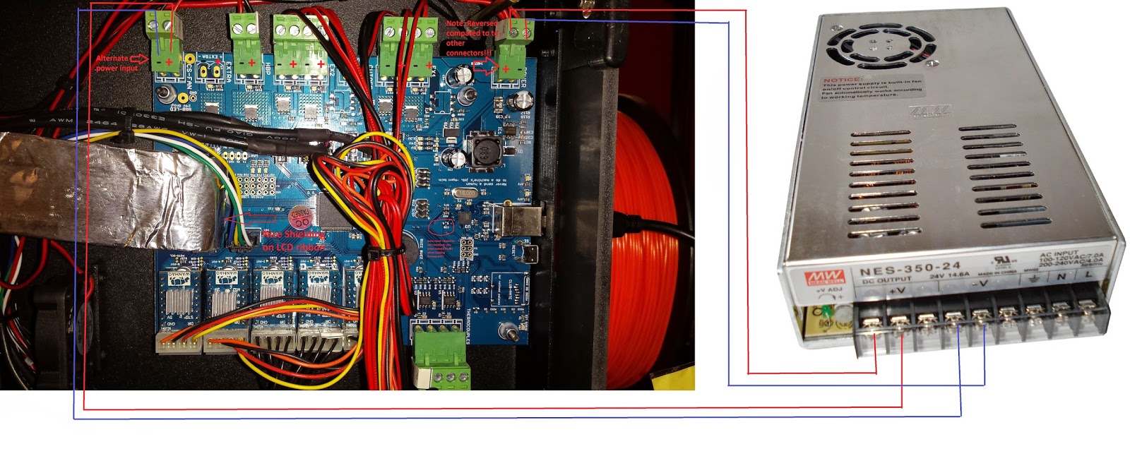
So really, you should set it up and use the 4 wires across the 2 possible power inputs but PAY ATTENTION TO POLARITY.

Why?? Because a single pin would SMOKE trying to carry 220 watts of power.
So, pins are doubled in parallel to share the load and not smoke and fail.
Which flips the script because on common mightyboard replacements and the printers sold using them often do smoke the single 2 pin input power connector when the heated bed is used a lot in a dual extruder setup.
So really, you should set it up and use the 4 wires across the 2 possible power inputs but PAY ATTENTION TO POLARITY.
It happens a lot in other brands and every once in a blue moon on a
Wanhao (mainly due to the other brand abusing the system with a higher
than normal power heated bed).

The fix is simple- the dual power input mod. The CS (Constant Source) connector is ALSO a possible power input to the mainboard.
Again, pay attention to polarity here. This is 100% correct for all Wanhao boards (this picture is in a Wanhao D4S).
Jetguy
Oct 24, 2015, 10:51:45 PM10/24/15
to Makerbot Users
Sorry picture nested for some reason

tramalot
Oct 25, 2015, 5:27:59 AM10/25/15
to Makerbot Users
just solder it direct, plugs are for ......
On Tuesday, September 22, 2015 at 9:49:55 AM UTC-4, H N wrote:

Dolf Veenvliet
Oct 25, 2015, 7:49:23 AM10/25/15
to Makerbot Users
Whoa... you can just plug the power into the cs output? I will do that if I get mine working again... and the shielding too!
H N
Oct 25, 2015, 11:06:53 AM10/25/15
to Makerbot Users
Ok so let me get this straight setting up a parallel circuit and splitting the power to 4 pins would maintain the 24V on pin, but cut the current in half, thus cutting the overall power to the pin to a 1/4, and making it so the pin can take the load without smoking. You show it running into the fan, and the power line what about the HBP?
Jetguy
Oct 25, 2015, 2:01:28 PM10/25/15
to Makerbot Users
What about the HBP???
Are you using the stock brick MakerBot PSU ?
Then you have no spare screw terminal to connect the positive lead of the HBP to, and therefore your only choice is to plug it into the board where it normally goes.
Are you using the stock brick MakerBot PSU ?
Then you have no spare screw terminal to connect the positive lead of the HBP to, and therefore your only choice is to plug it into the board where it normally goes.
tramalot
Oct 25, 2015, 4:09:46 PM10/25/15
to Makerbot Users
life cycle on a switch 50k, life on a plug 200k
H N
Nov 12, 2015, 9:42:08 AM11/12/15
to Makerbot Users
Hey Thanks everyone I have the board up and running, I did find a short in the x-endstop cable and am replacing it. Everything else went fine, I have the meanwell PSU hooked up. Now I believe I only have 2 questions left. How do you run the HBP to the PSU, so that the board and the hbp both pull from the psu? Also what is the connector to plug the stepper cable into the board. I'm using a flash forge board.
Thanks yall for helping me out on this.
Thanks yall for helping me out on this.
Reply all
Reply to author
Forward
0 new messages