Halloween LED Class
21 views
Skip to first unread message

Michelle Leonhart
Sep 16, 2012, 11:20:37 PM9/16/12
to la-mak...@googlegroups.com
Breaking off into a new thread to keep from flooding the original...
Here's some brainstorming:
*Waivers
Kids are crazy and soldering irons are burny. We should draft a quick waiver to help keep us from getting sued.
*Supplies / Ideas
We should decide if we want to do "LEDs" or "EL Wire". We could swing both, but would need a lead for each thing if we did. I think it would be cool if whatever they made was visible enough to help keep them safe at night while running around in the dark getting candy.
*If we do LEDs, I'd say we should decide on a super-minimal circuit, and have kids solder that together and stick it to some kind of halloween-themed foam pin or something that they could wear. Or they could make necklaces? Or candy bags? Pros: Wicked easy soldering. Cons: LEDs are small and not too visible from a distance in small numbers. (Could resolve this by getting ultrabrights and making them blink. OR go crazy and get those 1-3W ones.)
I'd estimate this to be on the low end of $5-$10/piece, depending on how much extra stuff we want to give them outside of the electronics themselves.
ex:
Power a 3W LED
Blinkie Pendant (These are cool for the brightness and the blinking. And, of course, we can make them any shape we want.)
*If we do EL Wire, the majority of the work will be teaching them how to solder something very delicate (corona wires are very small), and then either sewing it or gluing it to their costume/candy sack/whatever. Kids would need a lot of help with the soldering. Pros: Way cooler looking. Cons: VERY delicate soldering would need older kids or lots of parental help.
EL Wire is ~$1.50/ft and requires a driver (~$8). So... $15-$20ish, depending on how much wire they get.
ex:
How to stick EL Wire to stuff (I usually just use hot glue.)

Joseph Chiu
Sep 17, 2012, 12:45:23 AM9/17/12
to la-mak...@googlegroups.com
My vote would be to go with medium-intensity LED's in T 1-3/4, as they are cheap and plentiful. I would avoid the higher-wattage LED's because of thermal concerns and because they need more support circuitry for power regulation (using series LED's is not so good at the higher wattage) -- just for perspective, a low-end soldering iron is 8 watts.
One idea that I had was that we can pre-make the "lantern" using a 3D printer -- and have a printer running during the event showing more laterns being made. The lantern would be the housing for the LED's and batteries. I can get printed circuit boards made, or we can do a bare-wire twist-and-solder style construction.
I suspect the cost to be toward $5 including batteries. $10 should be plenty.
I've worked with EL wires before --- they look way cooler, but you do need to make sure the wire-ends are properly capped off so that we don't zap kids with 1 kV. Not dangerous, but painful. And, as Michelle pointed out, the drivers alone can run a few dollars before you do anything else, although we might just be able to buy some off eBay/Alibaba from a Chinese vendor if we pull the trigger quickly enough. (See http://www.ebay.com/itm/7-5FT-El-wire-glow-wire-cool-neon-battery-driver-Kelly-/120658209773?pt=US_Car_Lighting&hash=item1c17ca2bed for example.)
.
--
You received this message because you are subscribed to the Google Groups "Los Angeles Makerspace" group.
To post to this group, send email to la-mak...@googlegroups.com.
To unsubscribe from this group, send email to la-makerspac...@googlegroups.com.
To view this discussion on the web visit https://groups.google.com/d/msg/la-makerspace/-/3E_JM-qY6y8J.
For more options, visit https://groups.google.com/groups/opt_out.

Tara Tiger Brown
Sep 19, 2012, 1:31:41 PM9/19/12
to la-mak...@googlegroups.com, joe...@joechiu.com
I'm putting you guys down for the 20th or 21st. I hope that works.
Joseph Chiu
Sep 19, 2012, 1:33:07 PM9/19/12
to la-mak...@googlegroups.com
Sounds good. About 20 kids?
To view this discussion on the web visit https://groups.google.com/d/msg/la-makerspace/-/WdEAQX85Qn8J.
Michelle Leonhart
Sep 21, 2012, 12:58:18 PM9/21/12
to la-mak...@googlegroups.com, joe...@joechiu.com
Lanterns are a cool idea. Do you have 3D printers on hand? If not, I can hit up the other Crashspace members and see if we can borrow the replicator for this.
Pre-printed circuit boards sounds pricy for a class of 20--unless you know somewhere cheap?
Also, I know Tara knows a few people into soft circuits. Would it be too odd to have some folks helping kids put Sparkle Kits on goodie bags or something? (Really dependent on space requirements.) Or we could break that into a separate event if we felt there was a draw for it.
Tara Tiger Brown
Sep 21, 2012, 2:53:13 PM9/21/12
to michelle leonhart, Joseph Chiu, la-mak...@googlegroups.com
No, we don't have a 3D Printer. Borrowing one would be great.
I like the Sparkle Kit Idea for our soft circuit folks.
Any ideas where you want to do the event? The Silver Lake Headquarters is always open for us, otherwise I can hit up io/la in Hollywood, indiedesk in DTLA...
To view this discussion on the web visit https://groups.google.com/d/msg/la-makerspace/-/287N7HvDRMAJ.
Michelle Leonhart
Sep 21, 2012, 3:09:15 PM9/21/12
to Tara Tiger Brown, michelle leonhart, Joseph Chiu, la-mak...@googlegroups.com
Let me talk to Crash and others about getting a replicator. If not, maybe we could borrow a Bukobot from Diego.
Michelle Leonhart
Sep 21, 2012, 3:14:16 PM9/21/12
to Tara Tiger Brown, michelle leonhart, Joseph Chiu, la-mak...@googlegroups.com
As for headquarters, I'm willing to go wherever we will be. I'd appreciate if someone in the group could help us secure a space while I headhunt helpers and printers.

Sharon Ann Lee
Sep 21, 2012, 3:18:14 PM9/21/12
to la-mak...@googlegroups.com, Tara Tiger Brown, michelle leonhart, Joseph Chiu
When is the date for this event again?
We can do it in my studio in Atwater if that location works.
Yes, waiver is a good idea. A kid got a glue gun burn at the ice cream social--nothing too serious but thankfully the parent was cool about it.
Sharon
Michelle Leonhart
Sep 21, 2012, 3:29:14 PM9/21/12
to Sharon Ann Lee, la-mak...@googlegroups.com, Tara Tiger Brown, michelle leonhart, Joseph Chiu
Oct 21st. ~20ish kids + their parent/guardian?
(We had a kid grab a soldering iron by the iron once. Also for us, the parent was cool. Sounds like cool parents take their kids to cool events!)
(We had a kid grab a soldering iron by the iron once. Also for us, the parent was cool. Sounds like cool parents take their kids to cool events!)
Michelle Leonhart
Sep 21, 2012, 4:56:15 PM9/21/12
to Sharon Ann Lee, la-mak...@googlegroups.com, Tara Tiger Brown, michelle leonhart, Joseph Chiu
Kyle Cothern from Crashspace has offered us his replicator, CAD experience (he's a launch engineer for spacex), and help for the event. I asked him to request access to the group so he can hop on this convo and chat with us.
Joseph Chiu
Sep 21, 2012, 6:01:43 PM9/21/12
to la-mak...@googlegroups.com
I have a Thing-O-Matic and a Replicator. 3D printing is slow, so I'd pre-print some pieces, and it'd be good if anyone else would like to pitch in to print some as well. I have a spool of orange, so maybe I can just model a Jack-o-Lantern looking thing.
I can get "bare" boards done for about $80 - $120 for 30 pieces, depending on design (size of PCB). Silk-screened would cost a bit more, but probably still under $200 I think. I'm willing to order a big batch, pass on the pieces needed for the class at cost, and then stock the rest for resale on my own.
All this really depends on the design -- so it'd be good to figure out what it should look like.
Soft circuits are cool, dunno if you have plenty of e-textiles, and if they are good enough for the LED current needed. How does one attach to the e-textiles? Solder? Conductive glue?
I think having it at the same event would be ok. Maybe offer different "tickets" for LED, EL, etc. ? So you can buy one, both, or multiple??
On Fri, Sep 21, 2012 at 9:58 AM, Michelle Leonhart <at0m...@googlemail.com> wrote:
To view this discussion on the web visit https://groups.google.com/d/msg/la-makerspace/-/287N7HvDRMAJ.
Sharon Ann Lee
Sep 21, 2012, 6:10:16 PM9/21/12
to la-mak...@googlegroups.com, Tara Tiger Brown, michelle leonhart, Joseph Chiu
As long as we cap it at 20 kids, we can do it at my studio in Atwater.
Michelle Leonhart
Sep 21, 2012, 6:24:54 PM9/21/12
to Sharon Ann Lee, la-mak...@googlegroups.com, Tara Tiger Brown, michelle leonhart, Joseph Chiu
Sharon: 20 kids + parents, or 20 kids? (We could ask folks to limit it to one parent per kid, if necessary.)
I'm also noticing that MakerBot Monthly (a meetup of bot enthusiasts) is the same day as our class. Maybe we could wrangle a bunch of them to come bring bots? Crowdsource the production of lanterns?
Kyle and I will be thinking up cool lantern ideas and maybe trying out some CAD and prints at Crashspace this Sunday. If anyone else would like to come, let me know. It will be super informal and brain-stormy. I was thinking of trying to make a cat head, or a pumpkin... cute stuff.
Sharon Ann Lee
Sep 21, 2012, 6:29:11 PM9/21/12
to la-mak...@googlegroups.com, Tara Tiger Brown, michelle leonhart, Joseph Chiu
20 kids + 1 parent
Michelle Leonhart
Sep 23, 2012, 12:45:14 PM9/23/12
to la-mak...@googlegroups.com
Kyle and I will be at Crashspace around noon today til' whenever. We'll be experimenting, brainstorming, prototyping, and seeing what comes of it. Hopefully we'll report back later today with some cool ideas!
All are welcome to come hang out or work with us. 10526 Venice Blvd, Culver City CA 90232
All are welcome to come hang out or work with us. 10526 Venice Blvd, Culver City CA 90232
Michelle Leonhart
Sep 23, 2012, 7:17:04 PM9/23/12
to la-mak...@googlegroups.com
Check out this crazy lantern prototype! This one's laser cut. Maybe we could pre-cut a bunch of lanterns and have kids assemble them together and put their hand-made circuits in. (We can make them much smaller than this if we go with this idea, and save on the price of the kit. I'm REALLY digging the 1W LED, though it is pricey.)
Kyle's printing a pumpkin out on the replicator right now... still in progress.
Kyle had another good idea, too: kids too young to solder who still want to participate could use tiny breadboards instead of PCB.
On Sunday, September 16, 2012 8:20:37 PM UTC-7, Michelle Leonhart wrote:
Kyle's printing a pumpkin out on the replicator right now... still in progress.
Kyle had another good idea, too: kids too young to solder who still want to participate could use tiny breadboards instead of PCB.
On Sunday, September 16, 2012 8:20:37 PM UTC-7, Michelle Leonhart wrote:
Michelle Leonhart
Sep 23, 2012, 7:17:44 PM9/23/12
to la-mak...@googlegroups.com
Oh, right. With links:
http://www.flickr.com/photos/crashspacela/
On Sunday, September 16, 2012 8:20:37 PM UTC-7, Michelle Leonhart wrote:
http://www.flickr.com/photos/crashspacela/
On Sunday, September 16, 2012 8:20:37 PM UTC-7, Michelle Leonhart wrote:
Joseph Chiu
Sep 24, 2012, 2:30:59 AM9/24/12
to la-mak...@googlegroups.com
Hi Michelle,
I really like the direction you went with those lanterns! Looks much nicer than what I had envisioned! What 1W LED are you using, btw?
I really like the orange plexiglass/film. Since we're filtering, a monochromatic amber/orange LED's is more efficient than a white LED.
Breadboards are good.
Joseph
--
You received this message because you are subscribed to the Google Groups "Los Angeles Makerspace" group.
To post to this group, send email to la-mak...@googlegroups.com.
To unsubscribe from this group, send email to la-makerspac...@googlegroups.com.
To view this discussion on the web visit https://groups.google.com/d/msg/la-makerspace/-/BiQC32cRmWsJ.
Joseph Chiu
Sep 24, 2012, 2:33:15 AM9/24/12
to la-mak...@googlegroups.com
On the subject of where to host the event - I talked to Diego at Deezmaker in Pasadena. He's somewhat open to the idea of having kids and parents at his hackerspace - it's a bit smallish, but should be fine for 20 kids + their parents if they are spread out over time. However, he's waffling because of liability concerns about kids working with irons. Has anyone on-list dealt with that issue before? It's just mostly about getting waivers, no?
Michelle Leonhart
Sep 24, 2012, 12:22:29 PM9/24/12
to la-mak...@googlegroups.com
Thanks, Joseph!
Diego's willing to host? He's a good friend and Crashspace member. I'll keep that in mind. I think his space is in the same boat as Crashspace: can only hold that many people if they don't all come at once, and doesn't have the proper insurance for minors. Waivers do protect us to some extent, but the details of the law go over my head. If he's not comfortable, we can find somewhere else. (We do still have Sharon's offer on the table.)
I'm going to work more on the lantern design tonight. Mainly scaling it down a bit, cheapening the materials, and testing a few ideas we had yesterday but didn't have to time proto out. (Kyle's printing out a 3D moon right now. We thought: how cool would it be if they could see some moons printed, then put their LEDs inside the moon and hang it inside the lantern as the "bulb"? We did a small test and it looked wicked, so I'll do some more experiments.) I also did a few experiments with engraving a background into mirrored acrylic and lighting it from below. That looked really awesome, too.)
I'm thinking along the lines of a kit build currently. I can't drag the lasercutter to wherever we go, so it's best to pre-cut any materials on that. Kids can take laser cut materials (that fancy stiff black cardboard stuff maybe?) and snap/glue them together to make the box, solder or breadboard their circuit, and assemble the moon (2 pieces) around the circuit.
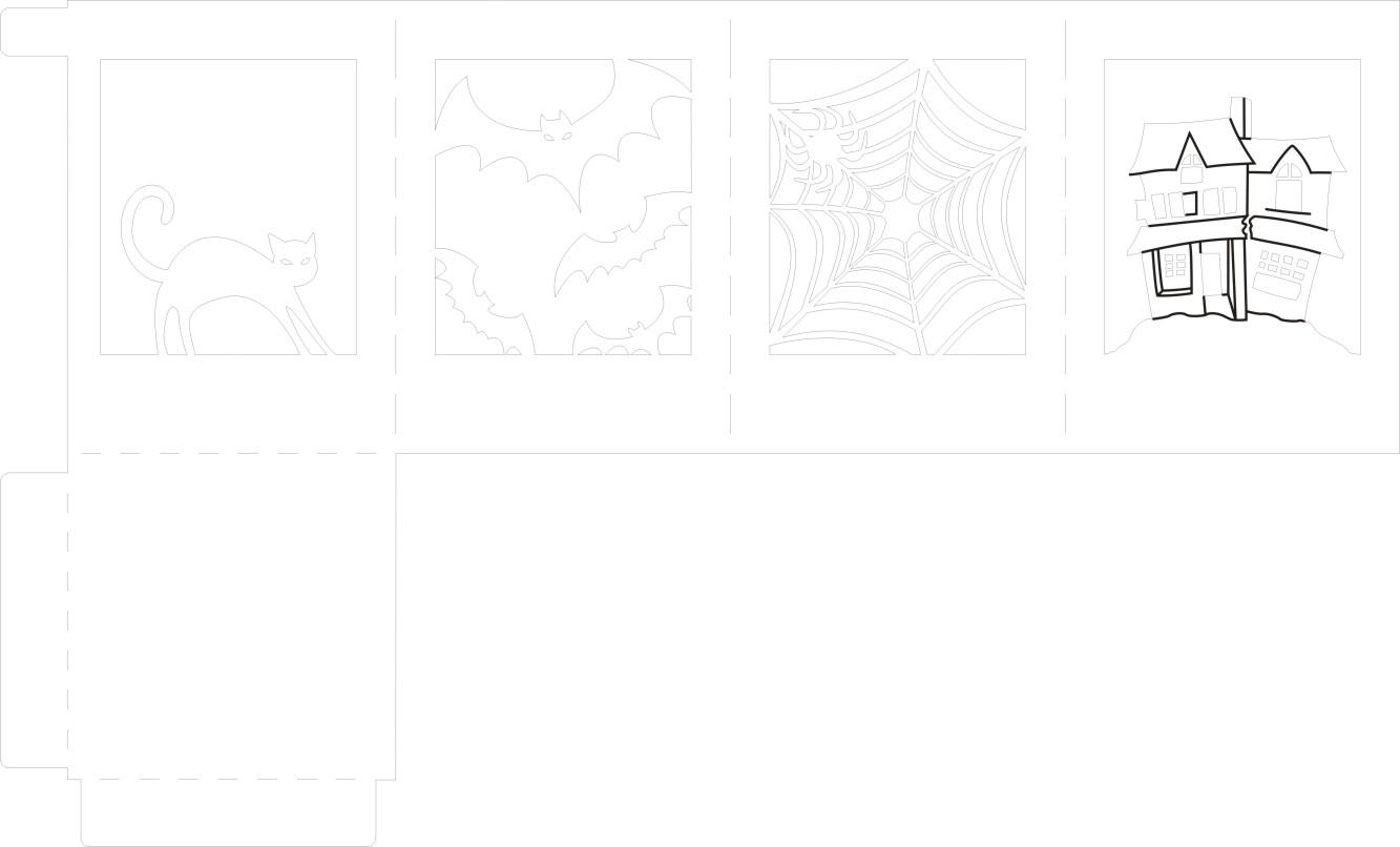
My only bummer with this idea is that kids can't really draw the designs on the lantern box, and they can't see them made. (We can have some printers printing more moons, at least, so they can see that.) Maybe I could design and cut lots of different halloweeny pictures, so they can at least choose the ones they want? And maybe instead of coloured acrylic, we could give them different coloured saran wrap they can choose?
Diego's willing to host? He's a good friend and Crashspace member. I'll keep that in mind. I think his space is in the same boat as Crashspace: can only hold that many people if they don't all come at once, and doesn't have the proper insurance for minors. Waivers do protect us to some extent, but the details of the law go over my head. If he's not comfortable, we can find somewhere else. (We do still have Sharon's offer on the table.)
I'm going to work more on the lantern design tonight. Mainly scaling it down a bit, cheapening the materials, and testing a few ideas we had yesterday but didn't have to time proto out. (Kyle's printing out a 3D moon right now. We thought: how cool would it be if they could see some moons printed, then put their LEDs inside the moon and hang it inside the lantern as the "bulb"? We did a small test and it looked wicked, so I'll do some more experiments.) I also did a few experiments with engraving a background into mirrored acrylic and lighting it from below. That looked really awesome, too.)
I'm thinking along the lines of a kit build currently. I can't drag the lasercutter to wherever we go, so it's best to pre-cut any materials on that. Kids can take laser cut materials (that fancy stiff black cardboard stuff maybe?) and snap/glue them together to make the box, solder or breadboard their circuit, and assemble the moon (2 pieces) around the circuit.
My only bummer with this idea is that kids can't really draw the designs on the lantern box, and they can't see them made. (We can have some printers printing more moons, at least, so they can see that.) Maybe I could design and cut lots of different halloweeny pictures, so they can at least choose the ones they want? And maybe instead of coloured acrylic, we could give them different coloured saran wrap they can choose?
Michelle Leonhart
Sep 24, 2012, 12:26:23 PM9/24/12
to la-mak...@googlegroups.com
Oh, and the LED:
https://www.sparkfun.com/products/9656
If we used that one, it would be costly @ 20 pieces. But the board helps with the heat issue (I left it running for quite some time and it felt fine), and it looks awesome. I ran it at 2.8V / 200mA(ish) and it was PLENTY bright. (Goes to 3V / 300mA) So we would likely be fine if we could find something a bit cheaper and slightly less intense.
Joseph Chiu
Sep 24, 2012, 2:08:44 PM9/24/12
to la-mak...@googlegroups.com
Yeah, those LED modules are pretty pricey. I've used plenty of them at work.
I've actually made a backlight illuminator with 120 1-watt LED's per board. It was bright and hot, and if you looked at it at the wrong time, you were temporarily blinded (like walking into a dark room after being outdoors).
I think the biggest problem is getting the right amount of power to the LED. We'd have to build a current-source regulator to provide the 200mA I(f). A simple battery/LED/resistor combination is not so good because you would either a) waste a lot of power with a higher-voltage source (probably 4x batteries so +V is ~6V) and a huge power-wasting current setting resistor; or b) you have poor regulation and the LED starts out way bright when the battery is fresh and goes dim very quickly when the battery voltage starts to sag, way before the battery is actually depleted.
I think you got away with it because you were using a variable power supply.
I like the use of the orange filter material in the lantern -- besides looking nice, that helps us in another way -- we can use a monochrome LED so that we can have a lower V(f), and also more output light per input power since we're not throwing most of the white light away.
This 1/2 watt PLCC Red-Orange LED is about 68 cents each at our target quantity -- http://www.digikey.com/product-detail/en/ASMT-QHB2-FEF0E/516-2469-1-ND/2744895 - they output 14 lumens. We'd want two of these per lantern to get comparable brightness, and then we need to put them on a PCB with the additional components to regulate current.
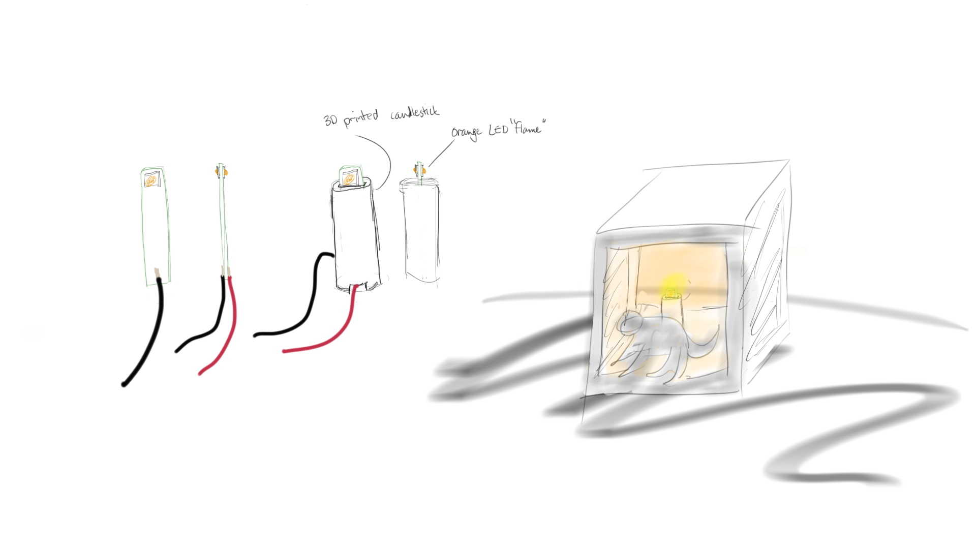
I was thinking of making the mounting board be candle shaped. Something like:

(see attachment for full-res)
I think that would look more like a proper lantern with a candle inside?
Joseph
--
You received this message because you are subscribed to the Google Groups "Los Angeles Makerspace" group.
To post to this group, send email to la-mak...@googlegroups.com.
To unsubscribe from this group, send email to la-makerspac...@googlegroups.com.
Michelle Leonhart
Sep 24, 2012, 3:17:39 PM9/24/12
to la-mak...@googlegroups.com
Good feedback. Help me think about a conundrum I'm stuck on for the electronics. I've been puzzling over it in the back of my mind all weekend.
What's the sweet spot between: (1) powerful enough to look awesome, (2) simple enough to be built and understood by kids who are young enough to not think trick-or-treating is lame yet (7-13?)
What's the sweet spot between: (1) powerful enough to look awesome, (2) simple enough to be built and understood by kids who are young enough to not think trick-or-treating is lame yet (7-13?)

michael wilson
Sep 24, 2012, 3:57:32 PM9/24/12
to la-mak...@googlegroups.com
What about 'power bracelets' very customizable, little or no soldering, and they work for both princesses and superheros!
http://makeprojects.com/Project/Soft-Circuit-LED-Bracelet/146/1#.UGC6xI1lRcQ
http://makeprojects.com/Project/Soft-Circuit-LED-Bracelet/146/1#.UGC6xI1lRcQ
Joseph Chiu
Sep 24, 2012, 8:54:13 PM9/24/12
to la-mak...@googlegroups.com
So I priced it out a little more. In retrospect, I think we'd want to make it just drive a single LED -- for a dual LED design, you'd just need an extra regulator, LED, and resistor (~+$1.50)
A battery holder for holding 3x AAA batteries - $1.30
LM317 regulator - $0.50
Resistor, 5 ohms, 1/2 watt - $0.10
AAA batteries, qty 3 - $0.90
LED - $0.70
So $3.50 plus the board the it will go on. It can be a piece of perfboard, or I can get boards made cheaply somewhere - probably around $3 per piece (if we're doing about qty. 20) -- so that's $6.50 in parts for electronics.
How does that sound to you guys?
On Mon, Sep 24, 2012 at 11:08 AM, Joseph Chiu <joe...@joechiu.com> wrote:
Joseph Chiu
Sep 24, 2012, 8:54:29 PM9/24/12
to la-mak...@googlegroups.com
Michelle Leonhart
Sep 30, 2012, 4:03:22 PM9/30/12
to la-mak...@googlegroups.com
I had a bit of time to draw and cut some designs for the other sides of the lanterns last night after our RFID class. (Check 'em out here: http://www.flickr.com/photos/crashspacela/ )
I'd like to pick up some cardboard and start shrinking the design. Joseph, do you know the size of the circuit's footprint? I'd like to make the lanterns just large enough to fit the circuit in the little 3D printed moon (which I'm currently picturing as perched on top of a little candlestick-like tube for support, with the battery pack on the bottom of the lantern. Notice that all lantern designs include an inch or so of solid material at the bottom--trying to leave room to hide a battery pack.)
Also, if you're ordering PCB, when do you think it'll arrive? I'd like to leave enough "oh shit" time between having the parts in hand and the class starting, so any emergency triage won't hurt us. Ideally, I'd like to hold off laser cutting the lanterns until we have the chips in hand, so we can ensure everything looks awesome together before mass-producing.
Do you have time to meet up this coming weekend? We should try to get you, me and Kyle together to make sure our designs all play nicely together.
Michelle Leonhart
Sep 30, 2012, 4:10:31 PM9/30/12
to la-mak...@googlegroups.com
We should talk pricing, too. I set the class at $20/person because Tara needed information by Friday, but we should make sure we can work in those bounds. Price braindump per student:
Materials
circuits: ~$8
cardboard: ~$1.50
Saran Wrap: ~$.30
Brads ~$.20 (I'm thinking of cutting the lanterns such that kids can fold them together and pin them with a brad or two. Easy, cheap, safe.)
Soldering Equipment & Expendables: Borrowed from Crashspace
R&D / Instructor Hours
Crashspace laser costs $2/min (I can eat this cost but would rather not.)
Makerbot PLA: I'll talk to Kyle/Matt about PLA costs and if they want to be reimbursed
Michelle's R&D Hours: pro bono
Michelle's Instruction Hours: pro bono
Kyle's R&D Hours: pro bono
Kyle's Makerbot Demo Hours: pro bono
Joseph's R&D Hours: ???
Joseph's Instruction Hours: ???
...anything I'm missing?

Kyle Cothern
Sep 30, 2012, 5:06:06 PM9/30/12
to la-mak...@googlegroups.com
Bono's ok, but I wouldn't say I'm nessecarily "Pro" Bono, I mean, with those glasses...
But dont' worry about reimbursement for the plastic, it's cheap and if it's for helping the children it's not going to destroy my budget.
--
Kyle Cothern
But dont' worry about reimbursement for the plastic, it's cheap and if it's for helping the children it's not going to destroy my budget.
if you guys could get me some dimensions on the board I could probably figure out how big to make the moons/what's reasonable. Or I could just print a few different sized moons and we could test everything out.
Also, if it's going to be supported by a stem instead of a string/wire I can change the design around a little to make it work better.
- Kyle
--
You received this message because you are subscribed to the Google Groups "Los Angeles Makerspace" group.
To post to this group, send email to la-mak...@googlegroups.com.
To unsubscribe from this group, send email to la-makerspac...@googlegroups.com.
To view this discussion on the web visit https://groups.google.com/d/msg/la-makerspace/-/XLP3RMFp0IYJ.
Kyle Cothern
SpaceX Launch Operations Mechanical Engineer
Joseph Chiu
Sep 30, 2012, 9:25:51 PM9/30/12
to la-mak...@googlegroups.com
Well, as long as we can come to an agreement by around the 10th or so, that'll be plenty enough time to get the boards done and shipped without panic. It's a simple board, so it'd be hard to screw up -- I'll send out a drawing with the circuit's minimum footprint a little later tonight (I need to get the kids to sleep - they're still a bit worked up form Maker Faire).
Could you make a simple sketch of what you have in the plans so far?
Thanks!
Joseph
--
You received this message because you are subscribed to the Google Groups "Los Angeles Makerspace" group.
To post to this group, send email to la-mak...@googlegroups.com.
To unsubscribe from this group, send email to la-makerspac...@googlegroups.com.
To view this discussion on the web visit https://groups.google.com/d/msg/la-makerspace/-/wyChziwEZYcJ.

Joseph Chiu
Oct 1, 2012, 10:36:11 AM10/1/12
to la-mak...@googlegroups.com, joe...@joechiu.com
Ok gang, I need your input.
TL;DR: Cheap, clever, and easy? Or proper design that cost more?
--
When I originally costed out the design, I hadn't carefully looked at the regulation voltage needed by LM317 in constant-current mode. It turns out that you need about 3V of overhead, and the power dissipation is pretty significant.
So I went back to the drawing board to look at alternatives.
Doing It The Right Way, of course, is to have a switching regulator in CC mode. It is theoretically the most satisfying, because you know you're squeezing out the most out of the batteries. But the BOM cost goes up a bit, and there are much more parts. Too many parts to get first-time soldering-iron users to get right in a limited amount of time. We could build the circuit up ahead of time, and leave the soldering to only hooking up wires.
Then, there's the Clever But Sloppy way using a PTC resistor, which turns out to be a really cheap way to do it. It's just the LED, the PTC resistor, and the battery pack. Cost goes down, too. But there's significant power dissipation in the PTC resistor, the current regulation is very sloppy, and there's far less uniformity of brightness between units, and over battery depletion time. But the bonus is: it's easy! And cheap!
So the practical side in me says go with the PTC.
The engineer / scientist side in me says go with the switching regulator.
And I think the simple moderate-cost LM317 approach is my least favorite -- if only because you'd otherwise have to lug around a 5-battery pack to make it work right. :(
Oh, and there's the traditional "LED + resistor" approach -- but that's not practical for high-bright application like this, since the system is highly sensitive to LED Vf and resistor values.
Joseph
Joseph Chiu
Oct 1, 2012, 10:43:58 AM10/1/12
to la-mak...@googlegroups.com, joe...@joechiu.com
BTW, I should point out that I can design the circuit board so that either approach is possible. There can be a "side A" with the simple design, and "side B" for the more complicated design...
Michelle Leonhart
Oct 1, 2012, 1:28:16 PM10/1/12
to la-mak...@googlegroups.com, joe...@joechiu.com
Since the event is for kiddies, I think "dumbing down" our circuits is a good idea. If we keep the circuit simple, we can keep the concepts simple, and kids can leave the event feeling accomplished because they've retained and can repeat what we've taught them.
On one hand, if we go with the PTC, we can tell them "There's a better, more efficient way to do this. But in this class, we're utilizing a beginner's approach." We could even bring both schematics, and hand out the more complicated one as a challenge for kids who want to take it up a notch in their spare time, if you want.
On the other hand, I don't think going with the better circuit and pre-soldering some of it is a horrible idea, though. How many parts do you estimate it'd be? For reference, at Crashspace, we teach beginning soldering with this board: http://lahack.com/ddd/technical-details/ and it goes very well, though we generally assist with the IC a bit.
Do you have a cost estimate for both circuits? We could make this class pretty pricey, if we want. The other classes are $60 a head. My only restriction is that I want to make sure we aren't making this a class that most families can't afford to attend.
--
Michelle Leonhart
Crashspace Membership and Treasury Officer
tinwhiskers.net || @at0mbxmb
crashspace.org
On one hand, if we go with the PTC, we can tell them "There's a better, more efficient way to do this. But in this class, we're utilizing a beginner's approach." We could even bring both schematics, and hand out the more complicated one as a challenge for kids who want to take it up a notch in their spare time, if you want.
On the other hand, I don't think going with the better circuit and pre-soldering some of it is a horrible idea, though. How many parts do you estimate it'd be? For reference, at Crashspace, we teach beginning soldering with this board: http://lahack.com/ddd/technical-details/ and it goes very well, though we generally assist with the IC a bit.
Do you have a cost estimate for both circuits? We could make this class pretty pricey, if we want. The other classes are $60 a head. My only restriction is that I want to make sure we aren't making this a class that most families can't afford to attend.
To view this discussion on the web visit https://groups.google.com/d/msg/la-makerspace/-/qjFhSEMg520J.
--
Michelle Leonhart
Crashspace Membership and Treasury Officer
tinwhiskers.net || @at0mbxmb
crashspace.org
Joseph Chiu
Oct 1, 2012, 1:42:33 PM10/1/12
to la-mak...@googlegroups.com
Any particular thoughts about surface-mount versus through-hole parts? Almost anything modern is SMT. None of the boost regulators that I was looking at came in through-hole. I did plan on leaded parts and largers SMD resistors/capacitors so that they can be tack-soldered with regular solder instead of having to use paste.
Do you have a toaster-oven reflow capability there? Maybe the thing to do is to demonstrate SMT, and then have the kids do the last bit of wiring with an iron?
So I think I'll go ahead and design both circuits -- have a "side A(dvanced)" and a "side B(eginner)".
Joseph
Michelle Leonhart
Oct 1, 2012, 2:01:28 PM10/1/12
to la-mak...@googlegroups.com
The age we're shooting for is 10, and we're not requiring previous experience. Surface-mount is difficult even for adults who have soldered multiple times in the past, so we should definitely be doing through-hole.
Joseph Chiu
Oct 1, 2012, 2:07:08 PM10/1/12
to la-mak...@googlegroups.com
Ok, I'll do my best to source through-hole's. The LED and the regulator will be SMT, though. No good way around that...
Michelle Leonhart
Oct 1, 2012, 9:41:50 PM10/1/12
to la-mak...@googlegroups.com
Quick update, just as FYI. Attached is a jpg of the lanter eps, so far. Just a few more minor tweaks to look and feel to go. The cut is currently ~1.5 minutes-ish. I may take the engraving off of the house to quicken the cut and lower the price on laser time.
Any cool ideas on how to mount the little moon? I like your candlestick idea, as it's sturdier than handing (and children are children.) We can print the sticks as part of the moon, and imbed them in the cardboard... or something like that...
Any cool ideas on how to mount the little moon? I like your candlestick idea, as it's sturdier than handing (and children are children.) We can print the sticks as part of the moon, and imbed them in the cardboard... or something like that...
Joseph Chiu
Oct 2, 2012, 12:53:37 PM10/2/12
to la-mak...@googlegroups.com
I saw the laser cut piece on the flickr stream and the artwork - looks great! Are the final pieces going to be made of black plexiglass or ?? And if I understand correctly, you're using orange-colored plastic wrap material on the inside?
Two requests -- can you put an array of smaller holes on the bottom of the lantern? The holes will allow cool air to enter the lantern, and will also provide mounting points for the circuit board and the battery holder. And, having some orange light "splash" out the bottom might be kinda nice.
I have parts ordered so that we can test a prototype this weekend. If we like it, we can get real boards made and order quantity for the event.
Thanks!
Joseph
On Mon, Oct 1, 2012 at 6:41 PM, Michelle Leonhart <at0m...@gmail.com> wrote:
Quick update, just as FYI. Attached is a jpg of the lanter eps, so far. Just a few more minor tweaks to look and feel to go. The cut is currently ~1.5 minutes-ish. I may take the engraving off of the house to quicken the cut and lower the price on laser time.
Any cool ideas on how to mount the little moon? I like your candlestick idea, as it's sturdier than handing (and children are children.) We can print the sticks as part of the moon, and imbed them in the cardboard... or something like that...
--
You received this message because you are subscribed to the Google Groups "Los Angeles Makerspace" group.
To post to this group, send email to la-mak...@googlegroups.com.
To unsubscribe from this group, send email to la-makerspac...@googlegroups.com.
To view this discussion on the web visit https://groups.google.com/d/msg/la-makerspace/-/EJX4BbedyMcJ.
Michelle Leonhart
Oct 2, 2012, 1:34:57 PM10/2/12
to la-mak...@googlegroups.com
I'm thinking 1/8" corrugated cardboard for the finished piece, to keep them from being wildly expensive. (We could likely only fit two on a $10 sheet of acrylic. The cardboard I found at a nearby craft store is $2.50 for a HUGE piece. (Cardboard pics here: http://www.flickr.com/photos/crashspacela/ from a bit earlier in the design process.) And as far as the plastic wrap, I'll see what colours I can find at the store so kids can pick and choose.
Want to meet at Crash over the weekend? Any time other than 2-5 on Sat works for me. (Kyle, you should come, too, if you can.) I'll save the holes until then, so we can make sure they fit with what you need.
Want to meet at Crash over the weekend? Any time other than 2-5 on Sat works for me. (Kyle, you should come, too, if you can.) I'll save the holes until then, so we can make sure they fit with what you need.
Sharon Ann Lee
Oct 2, 2012, 2:32:07 PM10/2/12
to la-mak...@googlegroups.com
Hi, are you guys set on a location for this class or do you need to use my studio?
thx,
Sharon
Michelle Leonhart
Oct 2, 2012, 2:37:04 PM10/2/12
to la-mak...@googlegroups.com
Hi Sharon,
Sorry! I thought you were in the loop on the space conversation. We didn't mean to leave you hanging like that. Tara offered Social Engine to us, so I think we'll use that. (I've been there before and it's quite spacious.)
Sorry! I thought you were in the loop on the space conversation. We didn't mean to leave you hanging like that. Tara offered Social Engine to us, so I think we'll use that. (I've been there before and it's quite spacious.)
Sharon Ann Lee
Oct 2, 2012, 2:45:55 PM10/2/12
to la-mak...@googlegroups.com
ok great, thx
Michelle Leonhart
Oct 2, 2012, 3:34:37 PM10/2/12
to la-mak...@googlegroups.com
Just took a look at the class on eventbright. Awesome. Do you guys think we should allow one free parent per child? We should put that on the evenbright. I don't want to end up with 10 kids / 10 parents. Much rather have 20 kids get 20 lanterns.
Michelle Leonhart
Oct 4, 2012, 12:21:42 PM10/4/12
to la-mak...@googlegroups.com
Let's meet up this weekend to finalize the design. Crashspace is closed from 2-5pm on Saturday (we have some serious cleaning to do), but any time other than that works for me.
Joseph Chiu
Oct 4, 2012, 7:13:52 PM10/4/12
to la-mak...@googlegroups.com
I can meet anytime Friday (better), or Saturday morning until about 1 pm (earlier the better). I have to take care of the kids rest of the Saturday, and I'm completely tied up Sunday.
Joseph
Michelle Leonhart
Oct 4, 2012, 7:23:32 PM10/4/12
to la-mak...@googlegroups.com
I can do Friday after 6pm, or Saturday until 1pm. I recommend Crashspace.
Joseph Chiu
Oct 4, 2012, 7:25:03 PM10/4/12
to la-mak...@googlegroups.com
Ok, let's do Crashspace Friday evening. Thanks!
Reply all
Reply to author
Forward
0 new messages