FPGA Bit Files for Testing and Big Lead on Rob's Problem

Steve Haynal
I have added 3 compiled bit files to github to facilitate testing, including 1 test that only requires a BeMicro SDK. Source code and a better description will come later. The good news is I was able to duplicate the problem Rob sees on his builds on my prototype and know what the problem is. On power up, the FPGA sometimes locks on at 2x or 1/2x the frequency of the AD9866 clock, or the AD9866 is generating 2x or 1/2x the specified frequency. When 2x occurs, you see the problem Rob has seen with low gain. When 1/2x occurs, you see the garbled audio that I sometimes see. There are probably settings with a PLL that can make this frequency lock more consistent but more investigation for a fix is needed.
The tests are in rtl/bitfiles and described below.
Hermes_Lite_NoAD9866
This test does not require a Hermes-Lite board, just a BeMicro SDK, and I would appreciate reports from people on how it works. It implements a single Hermes receiver/transmitter but the receiver is fed a sine wave at 4.607 MHz. You can connect to this with any Hermes software and see a strong signal at 4.607 MHz. It is interesting to see how various software and the FPGA processing produce artifacts with no real input. If someone has an inclination for analysis, this would be an interesting setup to analyze. You can vary the input and see/measure any distortion or noise through the entire chain. You can program the bit file on your BeMicro SDK with the standard Altera Quartus programmer. Once programmed, you can use the HPSDRProgrammer_v2_nopcap to write the firmware. It requires that you connect it to a network with a DHCP server to obtain the IP address. All the bit files use a fixed MAC address of {8'h00,8'h1c,8'hc0,8'ha2,8'h22,8'h5c}.
The 8 LEDs on the BeMicroSDK in this test are:
LED0 FPGA_PTT
LED1 Receiving any ethernet traffic
LED2 Receiving ethernet traffic for this MAC
LED3 Sending ethernet traffic
LED4 Synced
LED5 Hermes_atten bit 4 (move the attenuator slider to see this change)
LED6 Hermes_atten bit 3
LED7 Heatbeat, turns on every 0.85 seconds, pretty much every second.
Hermes_Lite_Test
This test implements a single receiver/transmitter with a fixed gain of +20 dB. The LEDs are as follows:
LED[0:1] ADCp and ADCn clips. Use this to check the balance of input signals.
LED[2:6] DAC level. Use this to see if a signal is being sent to the DAC.
LED[7] Heartbeat, turns on every 0.85 seconds.
The first time I turned on this test, the heartbeat was twice as fast and I saw the same problems Rob sees.
Hermes_Lite
This is the stock 2 receiver build. It was built with Quartus 14.01 using the latest code in github. I tested it on my prototype.
73,
Steve
KF7O
Steve Haynal

joe
I loaded the Hermes-lite-NoAD9866 .sof file to my Altera board (I think) and I can see s signal at 4.06MHZ using PowerSDR however as a complete novice I would like to comment
on a few problems.
The LED's on my board start the count from 1 not 0 all the functions work such as PTT and the attenuator just moved one count up the heartbeat shows on LED 8.
I don't know how the setup Hermes-lite using power SDR. I see Hermes listed but no hermes-lite as I use the normal Hermes selection I have no audio as the Hermes board must have it's audio output on board.
You and Rob are light years ahead of me and it it wasn't for Sid's help I wouldn't have gotten this far.
Joe wa9cgz near Chicago
Steve Haynal
- Power down the BeMicro SDK completely and wait for 20 seconds
- Power it back up
- Program with the SOF (skip this step if you have written the EEPROM with the HPSDRProgramming software)
- Connect with PowerSDR and verify that the signal is there
joe
I loaded the code several times so far so good. I was able to use the VAC as you suggested and now have audio.
Now the hard part could you or someone show me how to load the .sof file into the eeprom or to a SD card so each time the ALTERA is powered up it will load and I don't
need to reprogram it keep in mind that I'm a novice with the FPGA.
Thanks joe wa9cgz

Rob Frohne
Download the HPSDRProgrammer_v2_nopcap. Then you can use it to discover the hermes-lite and program it. I just tried it and it works for me.
73,
Rob
KL7NA
--
You received this message because you are subscribed to the Google Groups "Hermes-Lite" group.
To unsubscribe from this group and stop receiving emails from it, send an email to hermes-lite...@googlegroups.com.
For more options, visit https://groups.google.com/d/optout.
Rob Frohne
This may not have been as clear as I would like. What I was trying to do was answer your question about how to make the firmware non-volitile.
73,
Rob
KL7NA
Rob Frohne
In case this might be a problem for you, you need to install the pcap libraries as mentioned here. I had them already installed.
73,
Rob
KL7NA
Steve Haynal

ik1xpv
Steve Haynal
Rob Frohne
Attached are the bitfiles I've been using. The Hermes_Lite_09SDK-v1.1.rbf has the same MAC address as the v-1.0 units. The other one, Hermes_Lite_09SDK-v1.1-mac.rbf has the MAC address increased by one.
Glad to see you built up a board. My procedure for bringing up a board is:
- Using the Programming Tool in Altera's suite, flash the code for use with no Hermes-Lite as you have done.
- Connect that via Ethernet and use the HPSDRProgrammer (no pcap version on Linux) to program one of the files I have enclosed here.
- Inspect very carefully under a microscope or magnifier looking
for bridges or bad connections. Look on both sides.
- Fix anything bad you find.
- Check that your power isn't shorted by a solder bridge or with an ohmmeter.
- Connect power and pray. Not necessarily in that order. :-) Watch the lights and ammeter on the power supply.
- Watch the lights and ammeter on the power supply.
- If all seems okay, try and ping the board.
- If all seems okay, run hpsdr-server and dspserver and qtradio.
73,
Rob
KL7NA
--
You received this message because you are subscribed to the Google Groups "Hermes-Lite" group.
To unsubscribe from this group and stop receiving emails from it, send an email to hermes-lite...@googlegroups.com.
For more options, visit https://groups.google.com/d/optout.
--
Rob Frohne, PhD, PE
Professor
EF Cross School of Engineering
Walla Walla University
100 SW 4th Street
College Place, WA 99324
(509) 527-2075
ik1xpv
Steve Haynal
ik1xpv
Steve Haynal
Rob Frohne
73,
Rob
KL7NA
Sent from my Android device with K-9 Mail. Please excuse my brevity.
ik1xpv
Hello Steve,
The clock setup I made is wrong as shown in the S/N results.
I use PowerSDR and Hermes Lite Test configuration with 80 MHz clock patch.
I connected a 50 Ohm load and measure the level in AM with 5 KHz wide filter.
-105 dBm at 1.8 MHz
-115 dBm at 3.5 MHz
-106 dBm at 10 MHz
-126 dBm at 14 MHz
-123 dBm at 21 MHz
-122 dBm at 28 MHz
The clocking must be revised for use of a 80MHz clock...
I have not jet tested the input ferrite transformer I wound over a C6 ferrite core.
I soldered the AD9866 and the pcb by hand using big lens and glasses (I'm 63!). I placed same flux and solder over the thermal pad before soldering the chip side pins.
Then with an air gun I rise the temperature till I saw the chip solder melt and the chip centering itself.
This is not the best way but in my case it seems ok.
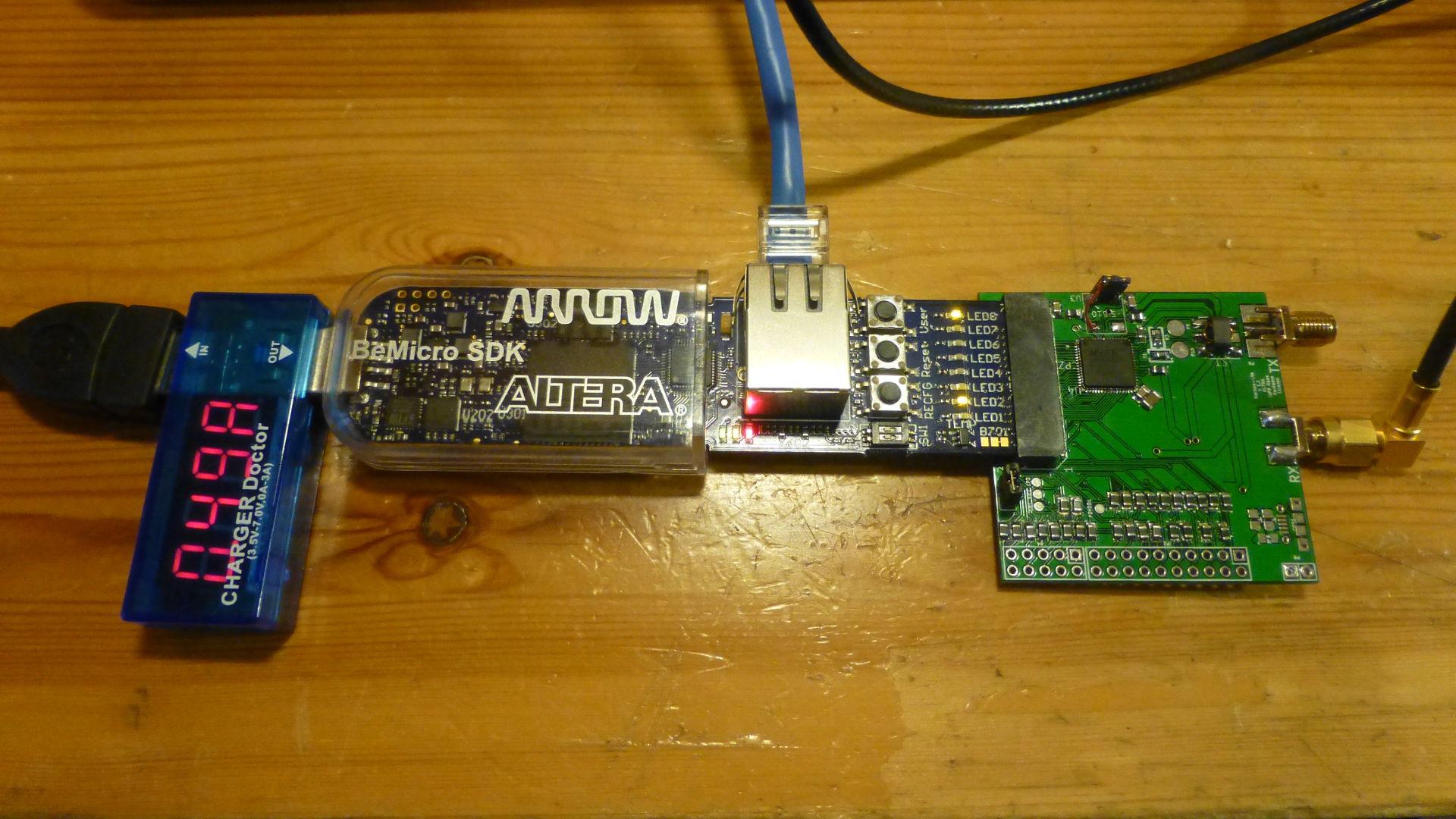
I power everything over the USB connector. I use a USB current monitor.
The mean current I measure is 500mA (moving from 480 to 510 mA).
The current of BeMicr SDK with Hermes_Lite_NoAD9866_09SDK.sof without Hermes Lite is 180mA.
73,
Oscar
IK1XPV
Steve Haynal
ik1xpv

Alan Hopper
Hermes_Lite_NoAD9866
This test does not require a Hermes-Lite board, just a BeMicro SDK, and I would appreciate reports from people on how it works. It implements a single Hermes receiver/transmitter but the receiver is fed a sine wave at 4.607 MHz. You can connect to this with any Hermes software and see a strong signal at 4.607 MHz. It is interesting to see how various software and the FPGA processing produce artifacts with no real input. If someone has an inclination for analysis, this would be an interesting setup to analyze.