PCB v-1.1 test

ik1xpv
Hello List,
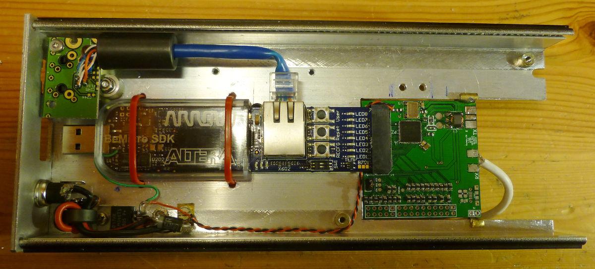
hereafter some report of PCB v-1.1 Hermes Lite
( https://groups.google.com/d/msg/hermes-lite/HfMIURmR_pA/Wf7A0S00FrwJ )
using the Hermes_Lite_Test firmware, modified with assignment of ad9866_rxclk to PIN_P14 instead of PIN_P11, to use with pcb 1.1
( https://groups.google.com/d/msg/hermes-lite/lFu49OLCt-s/2n_J-M82TIQJ )
The PCB is Rob's v-1.1 equipped with the 73.728 MHz osc. Thanks to Steve and Rob advices
( https://groups.google.com/d/msg/hermes-lite/lFu49OLCt-s/z3c17JshmFAJ ).
Settings:
Hermes-Lite running Hermes_Lite_Test Steve's firmware with default gain, +20 dB.
Window 7 64 bit running PowerSDRTM OpenHPSDR mRX PS v3.2.19 (8/29/14)
no NB or ANF
AGC slow
mode: USB
filter: 5 kHz
50 Ohm load connected.
The readings were taken from the the dBm meter, I report the mean value, the reading was +1, 0, -1 dB.
-131 dBm at 4MHz
-131 dBm at 7MHz
-130 dBm at 10MHz
-129 dBm at 14MHz
-129 dBm at 21MHz
-127 dBm at 28MHz
The result is very similar to Steve's one:
https://groups.google.com/d/msg/hermes-lite/0CMOG6NKilI/RAnCiE_DJF8J
The BeMicroSDK and the HermesLite are powered via a linear power supply 7805.
I placed an aluminum thermal radiator on top of the AD9866 with a rubber thermal pad.
During RX it reduced the IC temperature of about 20°C from 60°C to 40°C .
I measured the receiver noise floor with and without the thermal radiator and I got no difference at all, following the AD9866 datasheet pagg 12-13. I keep the radiator in case it helps to increase the life of the IC, maybe in TX condition ( to be tested ).
Thanks to Steve, Rob and all the List for the support.
73',
Oscar
IK1XPV

Steve Haynal
ik1xpv
Hi Steve,
PowerSDR is fine on Win7, as you wrote, it is possible to use VAC audio path to listen via PC speakers.I used IP direct Ethernet connection to Hermes Lite (APIPA). No server in between.
I understood that in Hermes Lite Verilog the AD9866 gain setting is controlled using the dither flag as most significant bit and then the other bits came from the attenuator setting. In PowerSDR the dither check button is in the HPSDR setup tab, it controls the AD9866 gain msbit. Under setting option tab you can select the attenuator steps and then use the GUI's combo box for attenuator selection. It modifies the gain setting in real time, but I didn't check the real gain levels yet.
For the noise level testing I used your Hermes_Lite_Test configuration with fixed 20 dB gain setting and just readings of the PowerSDR dBm meter.
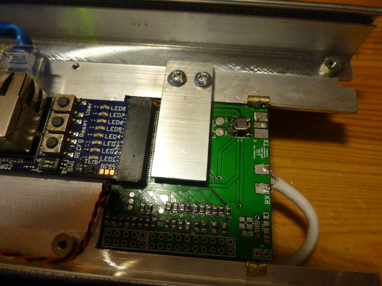
<< Did you have to add a capacitor for reset to function correctly? >>
At the beginning I used the 100n capacitor, then I made a cut on the pcb and connected the AD9866 reset with a wire patch to RESET_EXP BeMicro SDK connector pin3. See following image. It seems to run ok.
<< What balun (core, windings) did you use for TX and RX? >>
In RX i used a 1: 9 balun. I used an Amidon FB-43-2702 binocular core.
2 turns primary and 3+3 turns secondary as described in http://f1frv.free.fr/main3c_Baluns.html
It would be 50:450 Ohm. The differential input impedance of AD9866 is 400 Ohm.
I have not jet made any serious test of the wound transformer. I operates but I did not tested its loss.
I have still to test the receiver with a calibrated generator and to verify the LNA gain setting and I made no test at all in TX mode. I verified that with the Hermes_Lite firmware (no Test mode) there are 2 RX instances running
The box comes from local flea-market. Possibly It was a Motorola Mobile ETACS cellular (I'm in Italy). It has an H internal shape and offer good heat-sink. I plan to use the other side to house the radio front end, amplifier and filter.
Audio?
Do you think possible in some way to reintroduce the Hermes audio output path. I imagine it could have a shorter latency than the PC path via VAC ? What is your thinking about?
73,
Oscar
IK1XPV