Core XY iteration - asking for feedback

vinvin
Hi guys
I wanted to make my own printer. This is it!
http://www.thingiverse.com/thing:588277
I went for a CoreXY (http://corexy.com) configuration with a bowden setup.
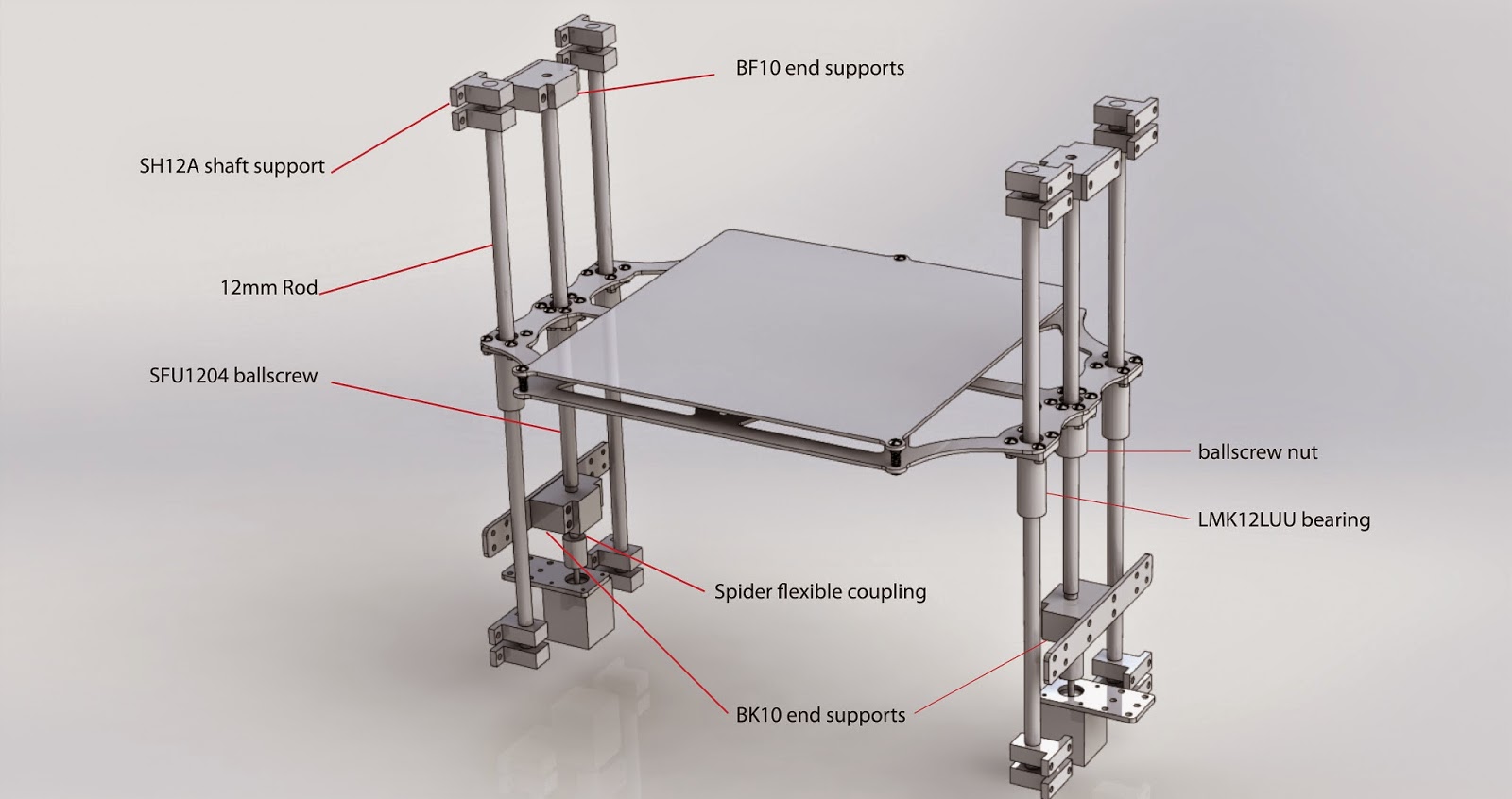
I decided to use SFU1204 ballscrew for the Z axis, synchromesh cables and guitar tensioning mechanisms. 10mm rod for the X axis, and 12mm for the Y axis.
I will be more than happy to read your opinions/critics/thougths about it!
ALSO : I haven't choose my electronic board yet, and doesn't know with one to choose. I wanted to go with 1/32 microstepping drivers since as i understood, Marlin implementation of corexy system divide the resolution by factor 2, and also for quietness of operation. Should I choose a 32bit capable board like the Azteeg X5 mini or a regular atmel 2560 will do?
vinvin


Jetguy
Jetguy

Double V arrangement for maximum belt wrap on every pulley and still only uses 2 idlers.

608 skate bearing idlers.

Motor and overall arrangement.


Moving stage plate detail from the bottom side.

vinvin
Jetguy
vinvin
Jetguy
vinvin
Jetguy

adam paul
I like your utilization of the 20x40 to offset the idlers, I was planning on using a plate, I may adopt your design. For my build I can rotate the bar the idler is on 90 degrees making it adjustable.
vinvin
vinvin
20x40? Are you talking about the extrusion? Those are 40x40mm aluminium extrusion. I placed this extrusion in that way so that the slot holding the pulley isn't parrallel to the belt tension
adam paul
Jetguy

vinvin
Jetguy

Ryan Carlyle
On the XY gantry, two thoughts:
1) Marlin is generally not fast enough to run a 1/32 stepping printer. Plus, 1/32 stepping doesn't improve resolution at all -- no microstepping over about 1/8th adds any resolution, because the marginal torque per microstep is too small to move anything. The only genuine advantage of 1/32 stepping over 1/16 is that it's a bit quieter. get stepper dampers first, and if you still think it's too loud, switch to 1/32 stepping drivers later.
2) You're going to want bigger idler bearings if you plan on running the printer hard. The smallest genuine synchromesh size is a bit big for 624v bearings. It works, but it's not a great sizing choice. You end up violating the minimum bend radius, which will dramatically shorten the fatigue life. Switching to 625v now shouldn't be too hard, I don't think. Another option to consider is ordering more expensive U-groove bearings (eg from Misumi) which will support the synchromesh cable with less vibration/stress and be dramatically higher quality than all the crappy Chinese 624v bearings (that I've found, anyway).
vinvin
Ryan Carlyle
Those 625 bearings don't have much groove depth -- you might get it to run ok and stay in the groove once everything gets tensioned up, but running the cable through the gantry may be hellish.

Viesturs Lācis
On Thursday, December 11, 2014 3:58:12 PM UTC+2, vinvin wrote:
Hi guys
I wanted to make my own printer. This is it!
http://www.thingiverse.com/thing:588277
I went for a CoreXY (http://corexy.com) configuration with a bowden setup.
I decided to use SFU1204 ballscrew for the Z axis, synchromesh cables and guitar tensioning mechanisms. 10mm rod for the X axis, and 12mm for the Y axis.I will be more than happy to read your opinions/critics/thougths about it!
adam paul
Ryan Carlyle
vinvin
vinvin
vinvin
Le mardi 6 janvier 2015 16:31:12 UTC+1, adam paul a écrit :