Identify Structure of this Tensegrity, help
441 views
Skip to first unread message

Tensegrity Wiki
Sep 12, 2016, 12:55:28 AM9/12/16
to geodes...@googlegroups.com
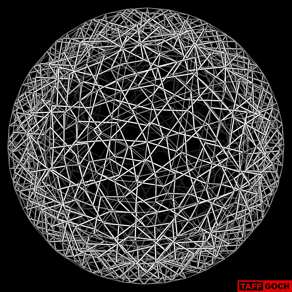
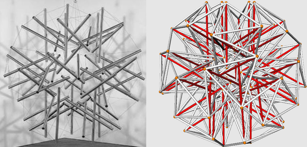
On the tensegritywiki, Kale11 raises a good question.
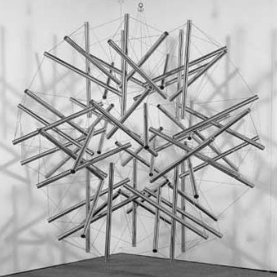
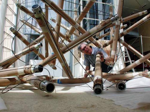
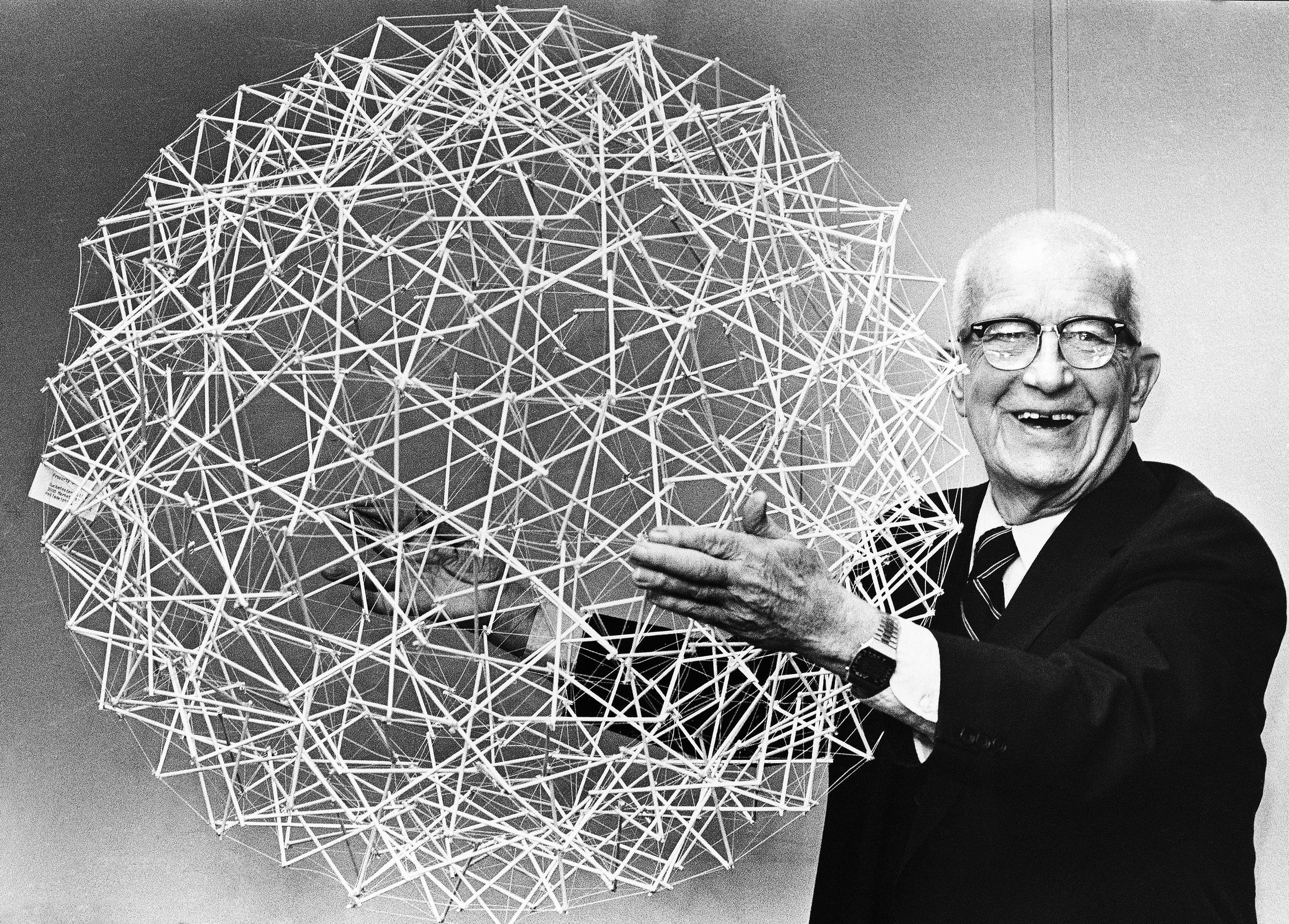
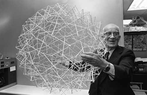
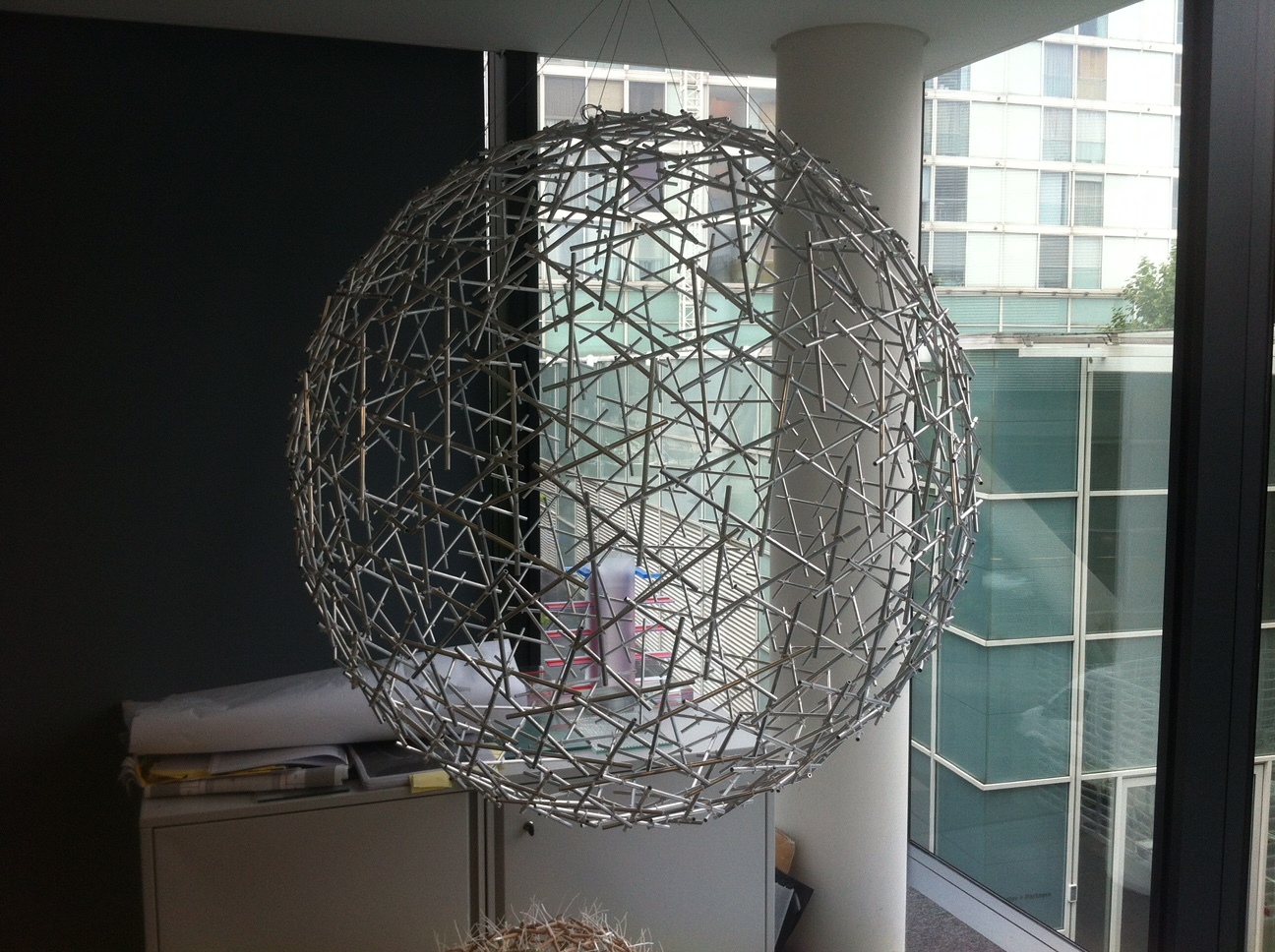
Is anyone able to say which tensegrity Bucky is holding in these photos? What is its structure?
http://allcompanies.website/wp-content/uploads/2015/11/3902eedf62d2a15e8549a8cf60fda820.jpg
http://static1.squarespace.com/static/52d45fb1e4b021f8239c4797/t/562a38cae4b052a65b365085/1445607627857/buckminster-fuller.jpg?format=500w
Some of the photos online are dated to April 18, 1979 if that helps.Is anyone able to say which tensegrity Bucky is holding in these photos? What is its structure?
http://allcompanies.website/wp-content/uploads/2015/11/3902eedf62d2a15e8549a8cf60fda820.jpg
http://static1.squarespace.com/static/52d45fb1e4b021f8239c4797/t/562a38cae4b052a65b365085/1445607627857/buckminster-fuller.jpg?format=500w

Ashok Mathur
Sep 12, 2016, 1:33:02 AM9/12/16
to geodes...@googlegroups.com
The structure looks like a nexorade.
Ashok
Regards
Ashok
Ashok
--
--
You received this message because you are subscribed to the "Geodesic Help" Google Group
--
To unsubscribe from this group, send email to GeodesicHelp+unsubscribe@googlegroups.com
--
To post to this group, send email to geodes...@googlegroups.com
--
For more options, visit http://groups.google.com/group/geodesichelp?hl=en
---
You received this message because you are subscribed to the Google Groups "Geodesic Help Group" group.
To unsubscribe from this group and stop receiving emails from it, send an email to geodesichelp+unsubscribe@googlegroups.com.
For more options, visit https://groups.google.com/d/optout.

TaffGoch
Sep 13, 2016, 1:06:39 AM9/13/16
to Geodesic Help Group
TW,
I'm sure this helps:
(I'll share more info, tomorrow -- I promise.)
-Taff
TaffGoch
Sep 13, 2016, 1:08:53 AM9/13/16
to Geodesic Help Group
TW,
It's called a "prism" tensegrity, by the way....
-Taff
Tensegrity Wiki
Sep 13, 2016, 2:33:57 PM9/13/16
to geodes...@googlegroups.com
TaffGoch, you are a living miracle. Amazing.
How many struts are in there? Could it all be one continuous tendon?
I look forward to more details, the frequency, etc. Did you generate that after seeing the image,or you had it already done?
--
--
You received this message because you are subscribed to the "Geodesic Help" Google Group
--
To unsubscribe from this group, send email to GeodesicHelp+unsubscribe@googlegroups.com
--
To post to this group, send email to geodes...@googlegroups.com
--
For more options, visit http://groups.google.com/group/geodesichelp?hl=en
---
You received this message because you are subscribed to the Google Groups "Geodesic Help Group" group.
To unsubscribe from this group and stop receiving emails from it, send an email to geodesichelp+unsubscribe@googlegroups.com.
For more options, visit https://groups.google.com/d/optout.
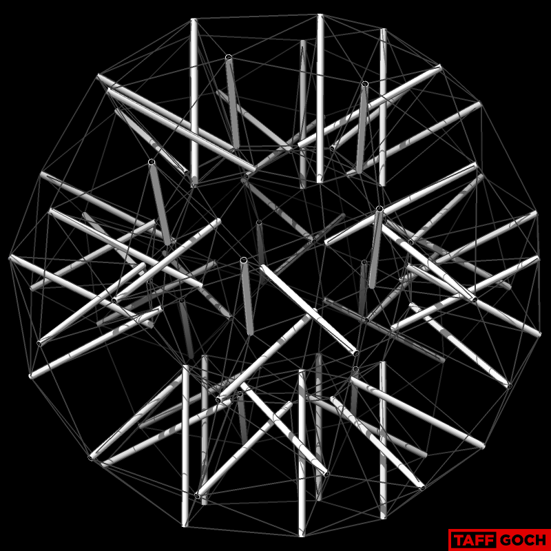
TaffGoch
Sep 13, 2016, 6:26:28 PM9/13/16
to Geodesic Help Group
TW,
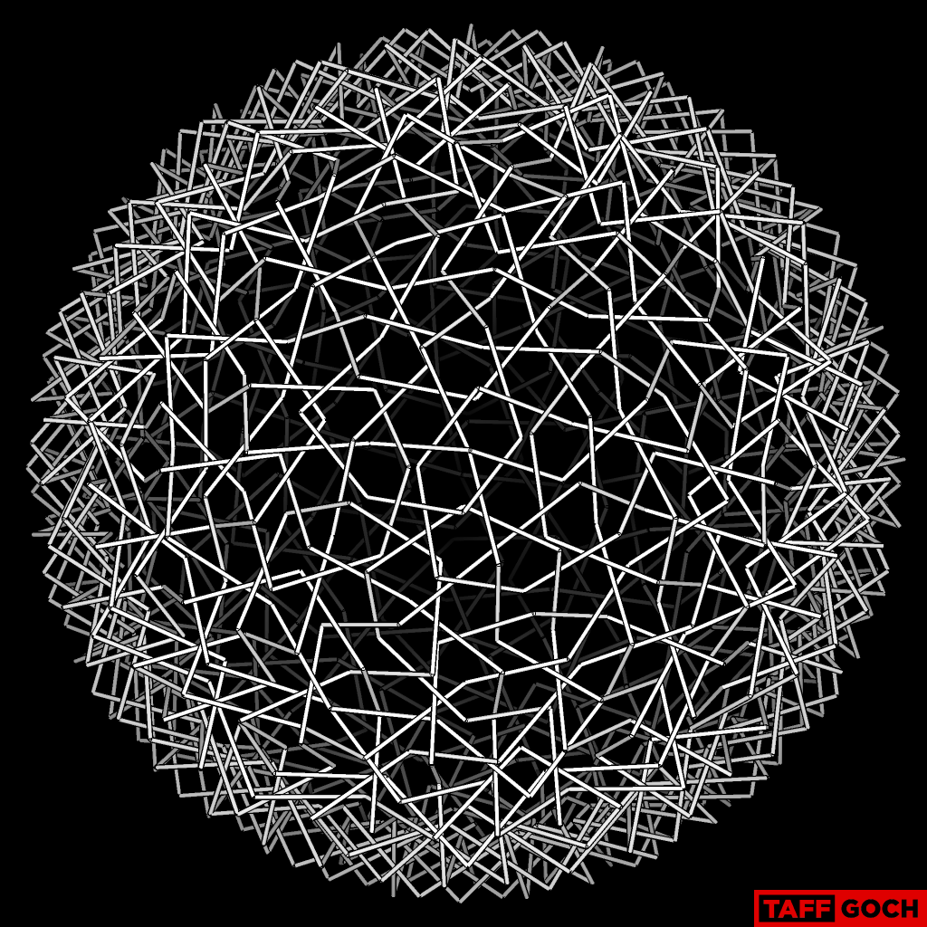
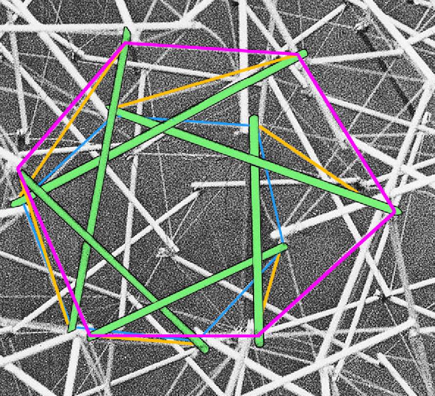
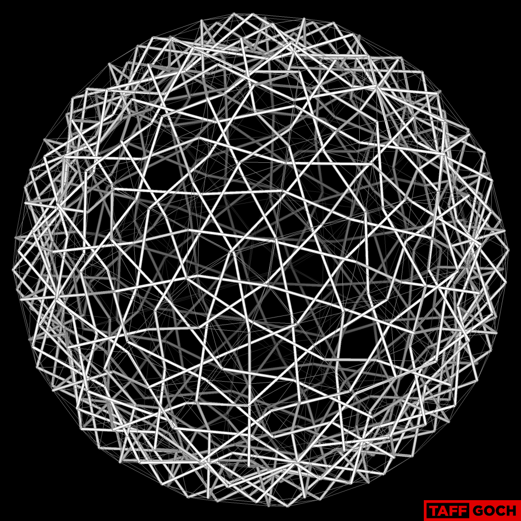
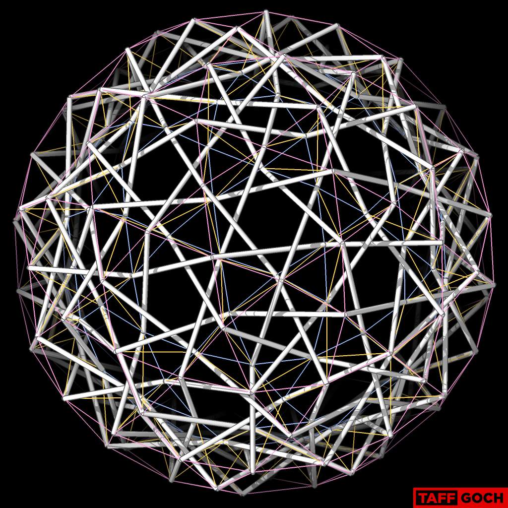
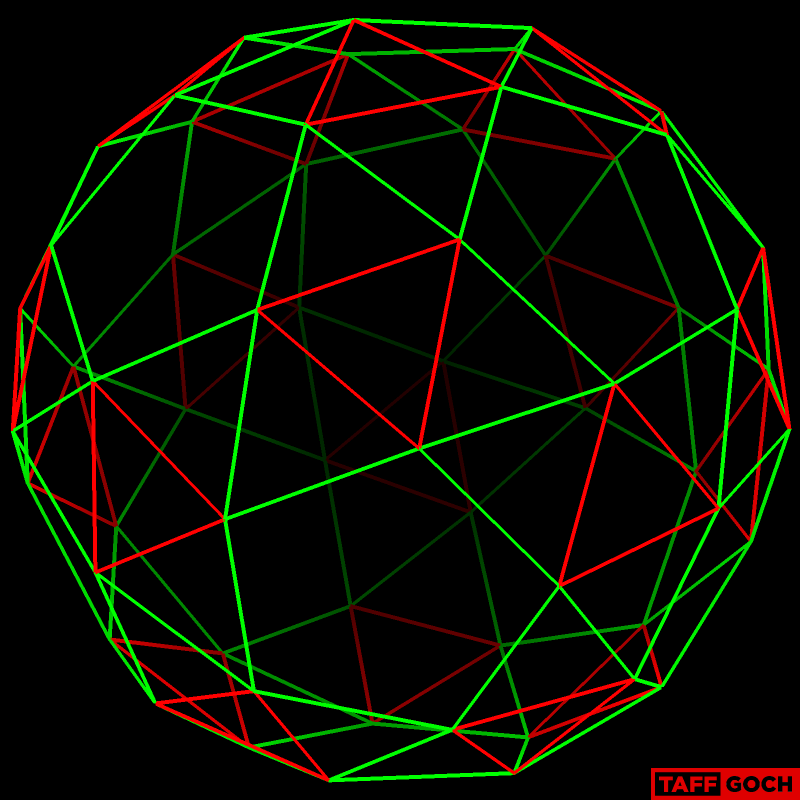
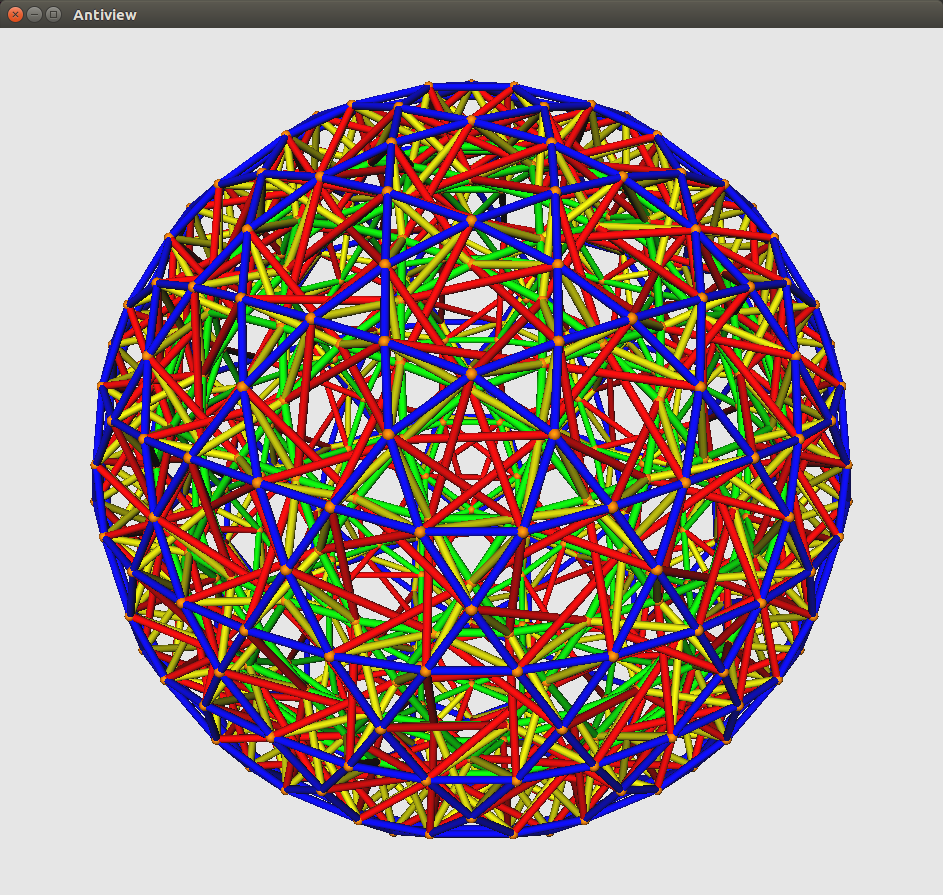
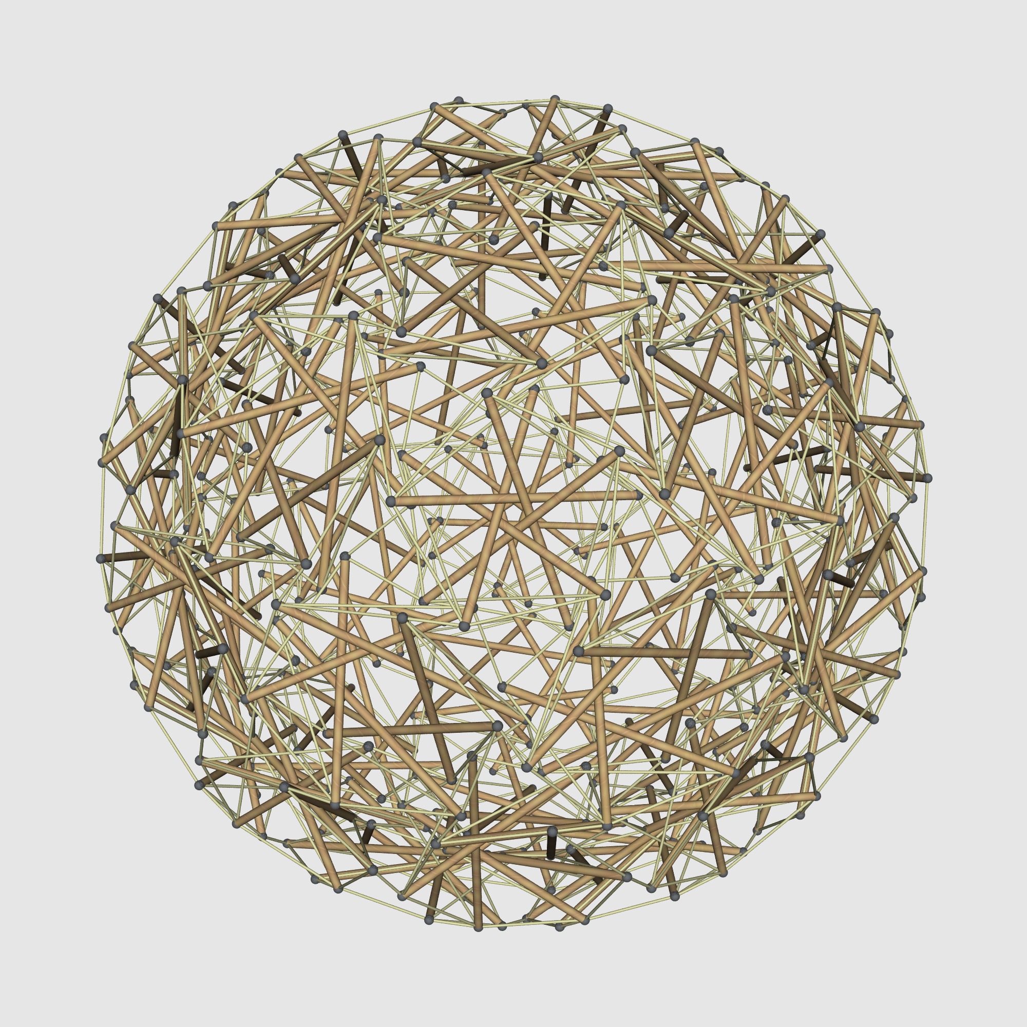
The Bucky sphere is a tensegrity sphere, composed of many adjacent prism tensegrties. You can see one, highlighted, here:
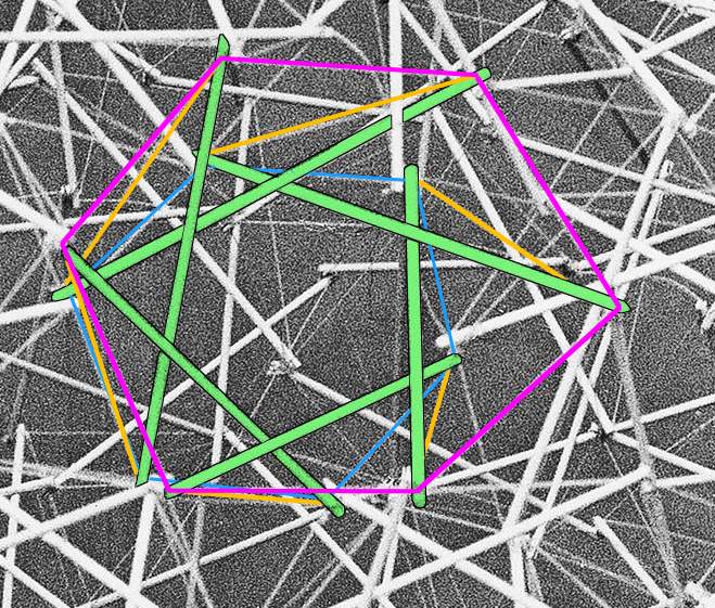
(The struts are green, the inner tendons are blue, the outer tendons are magenta, and the interstitial tendons are orange.)
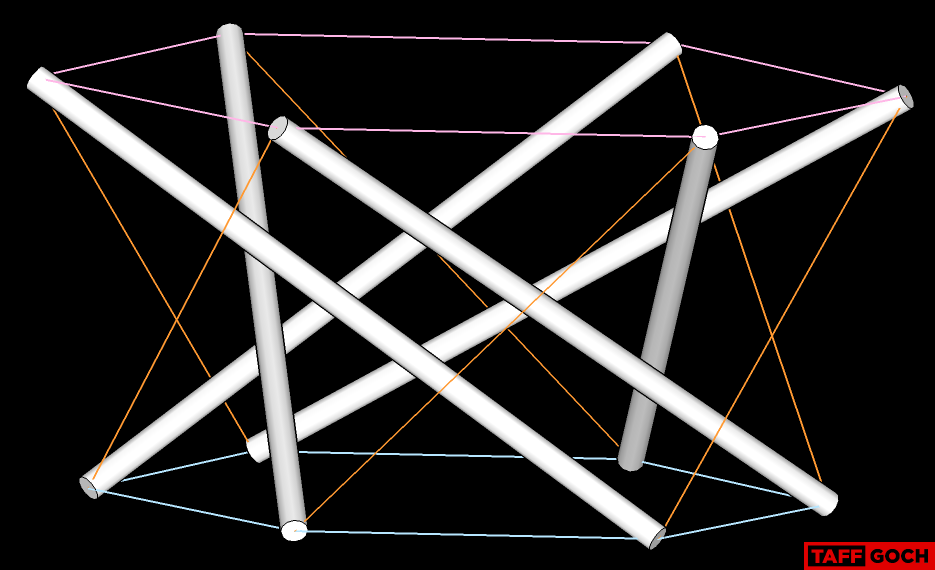
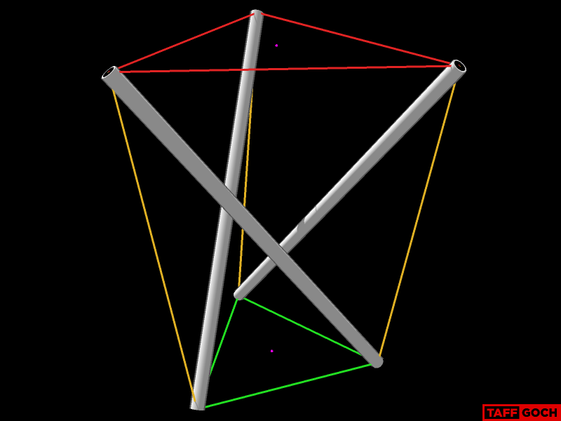
One prism, isolated from the model:
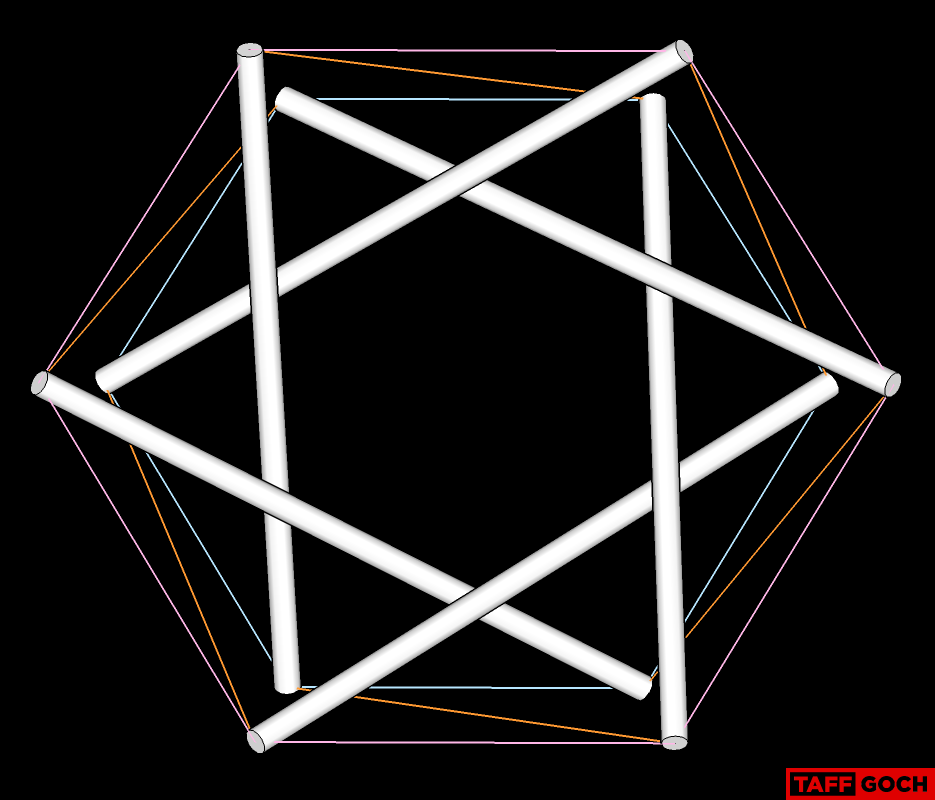
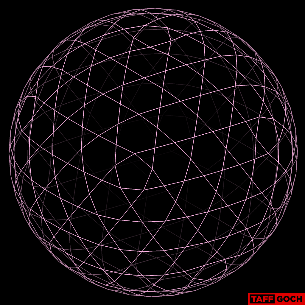
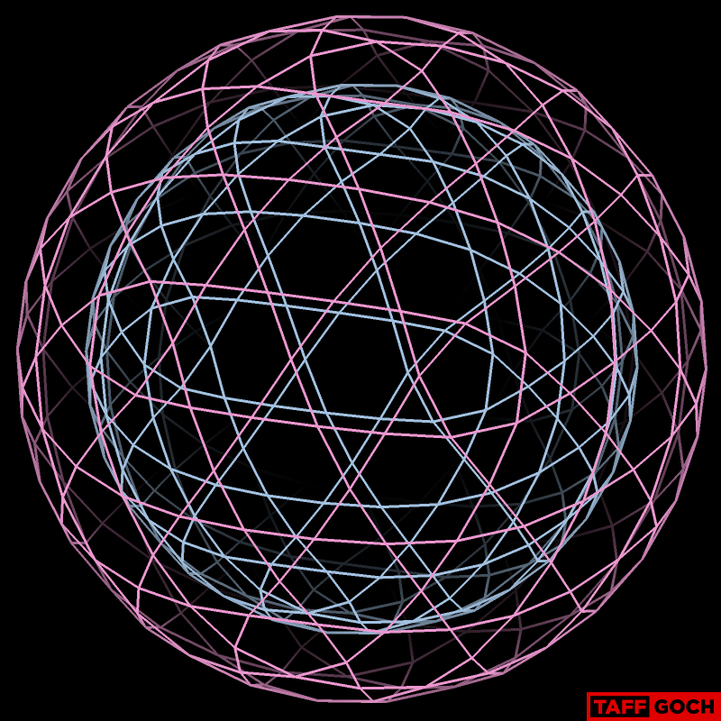
The outer tendons reveal the icosahedron geometry:
The inner-strut set is a scaled-down version of the outer tendons:
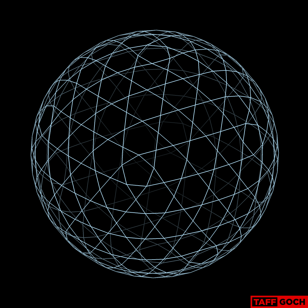
Inner & outer tendons, depicted:
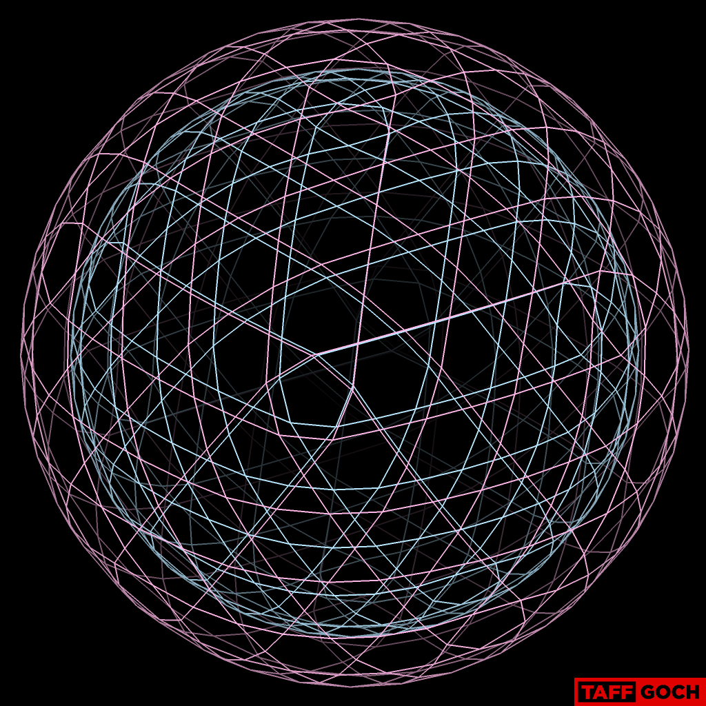
Interstitial tendons, only:
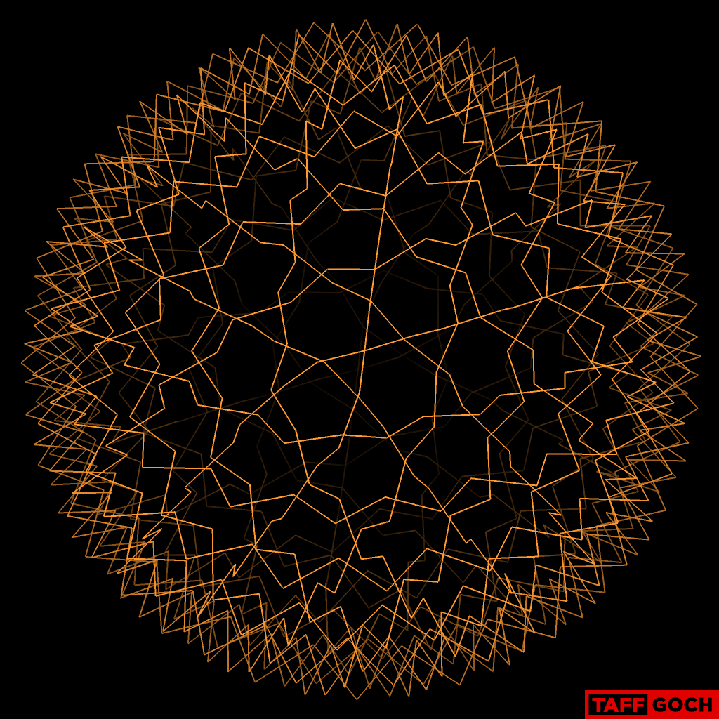
All tendons:
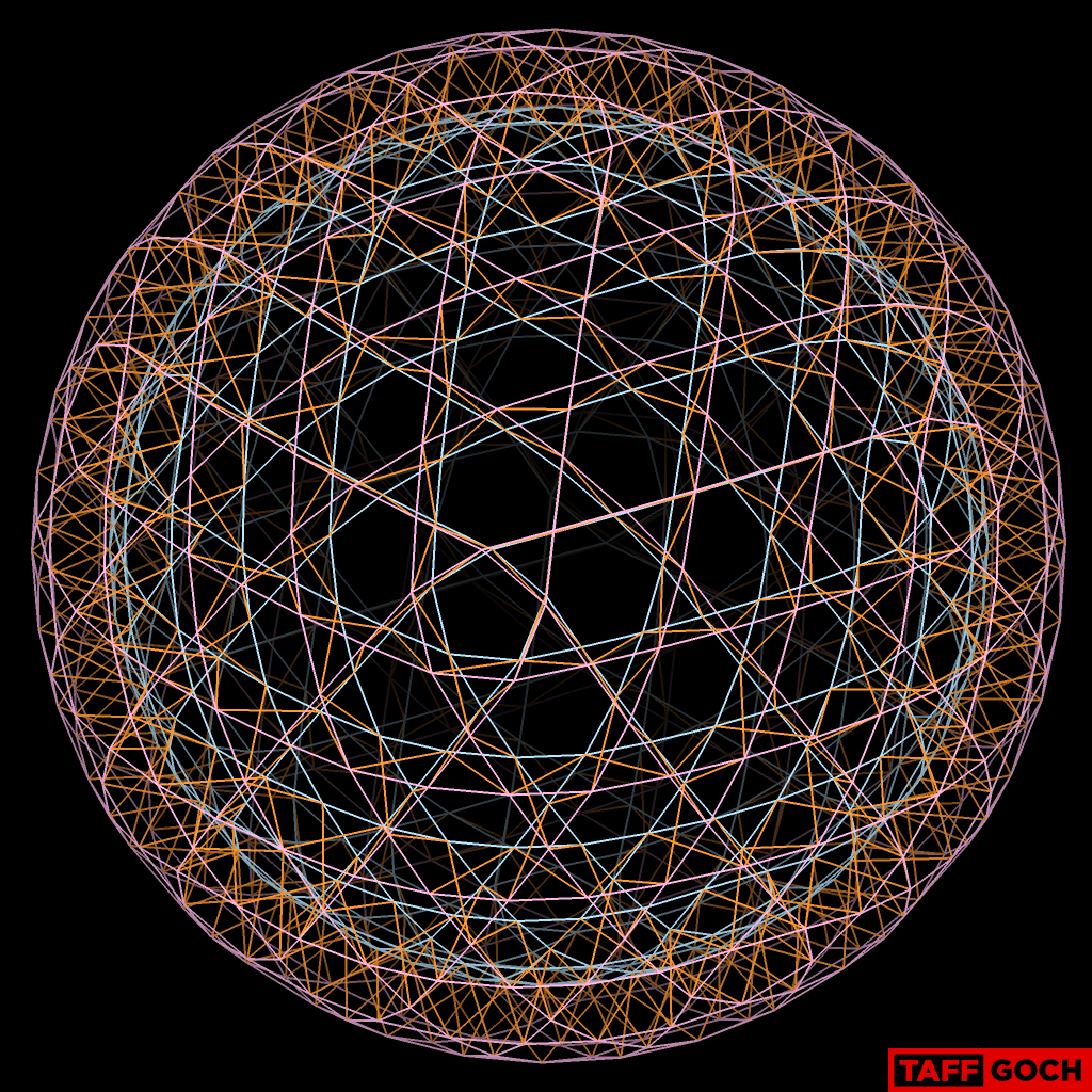
All compression struts and tendons:
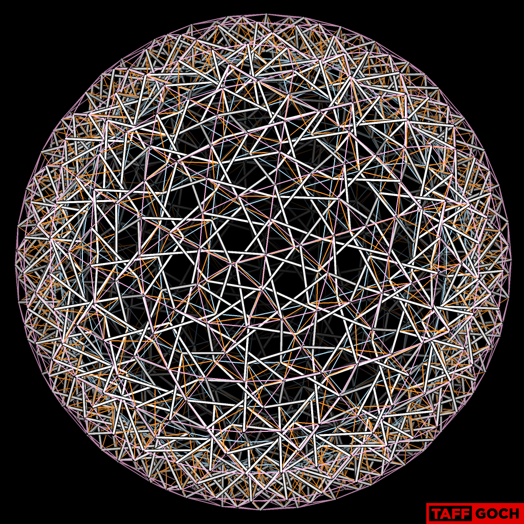
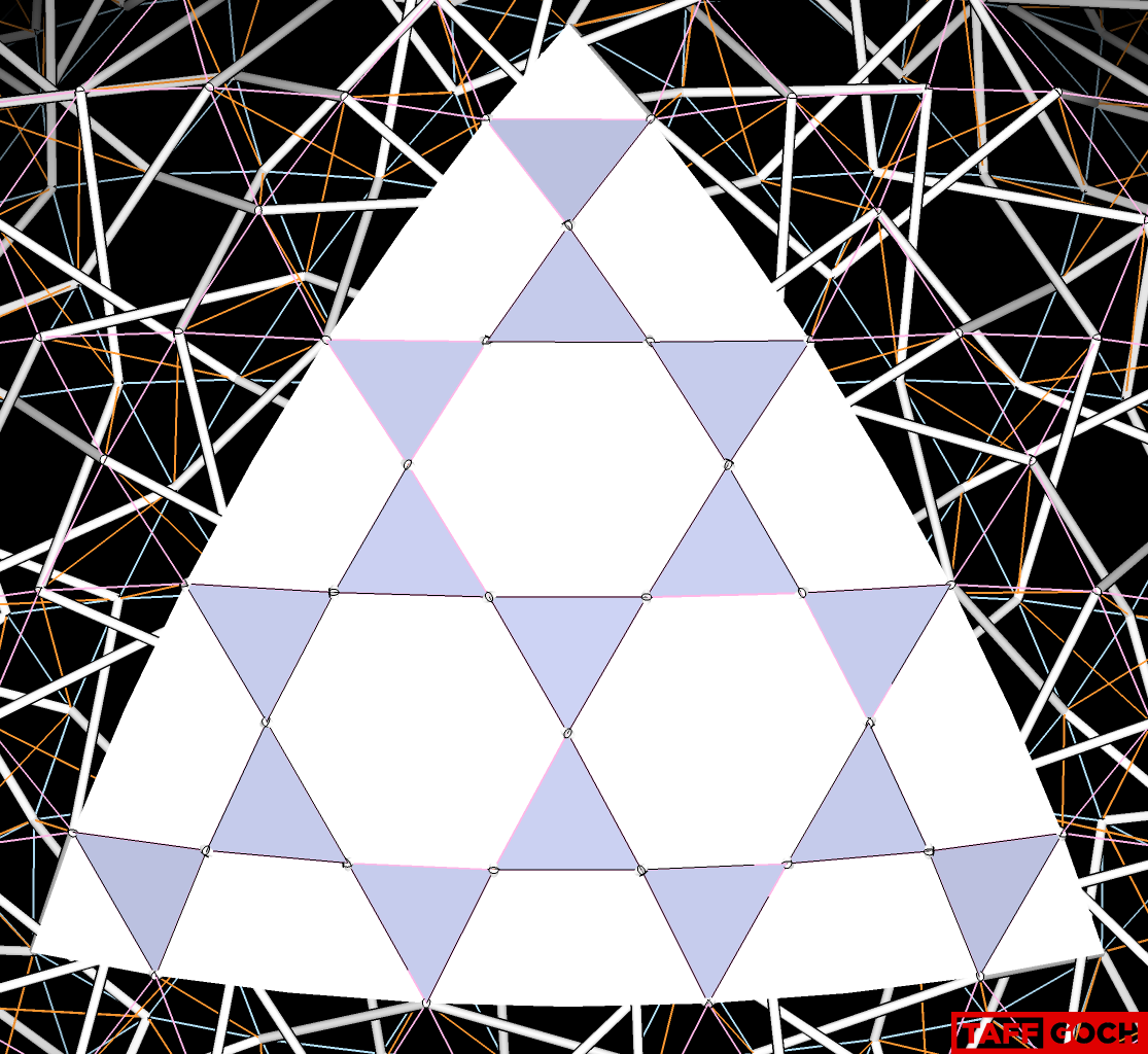
8-frequency icosahedron face geometry:
I have had the
Bucky photo in my computer "library" for some time, and had always
intended to study it further, to determine its geometry and
construction. Your query challenged me to get to it, and try 3D
modeling. I reverse-engineered the geometry and developed the model only
yesterday.
-Taff
TaffGoch
Sep 13, 2016, 6:48:30 PM9/13/16
to Geodesic Help Group
I mistakenly-referred to "the inner strut set" in my previous post (above the image of the blue inner tendons.) The reference should have been, obviously, "the inner tendon set."
_________________
_________________
I also noted that the photoshopped image, depicting one of the prisms in the 1979 photo, had a strut crossing under another strut, which should have been depicted as crossing over. That's been corrected in the image below:
-Taff
TaffGoch
Sep 13, 2016, 7:56:03 PM9/13/16
to Geodesic Help Group
TW,
There are 150 hexagonal prisms, and 12 pentagonal prisms.
To physically reproduce the sphere in the photo: Since each prism is rigid, each can be assembled separately, then connected to adjacent prisms, by the corners (not the edges.)
To physically reproduce the sphere in the photo: Since each prism is rigid, each can be assembled separately, then connected to adjacent prisms, by the corners (not the edges.)
-Taff
Ashok Mathur
Sep 13, 2016, 9:48:13 PM9/13/16
to geodes...@googlegroups.com
A tour de force!
Ashok
Regards
Ashok
Ashok
--
Message has been deleted
Message has been deleted
TaffGoch
Sep 14, 2016, 11:32:44 PM9/14/16
to Geodesic Help Group
TW,
It appears that I was somewhat overly-ambitious....

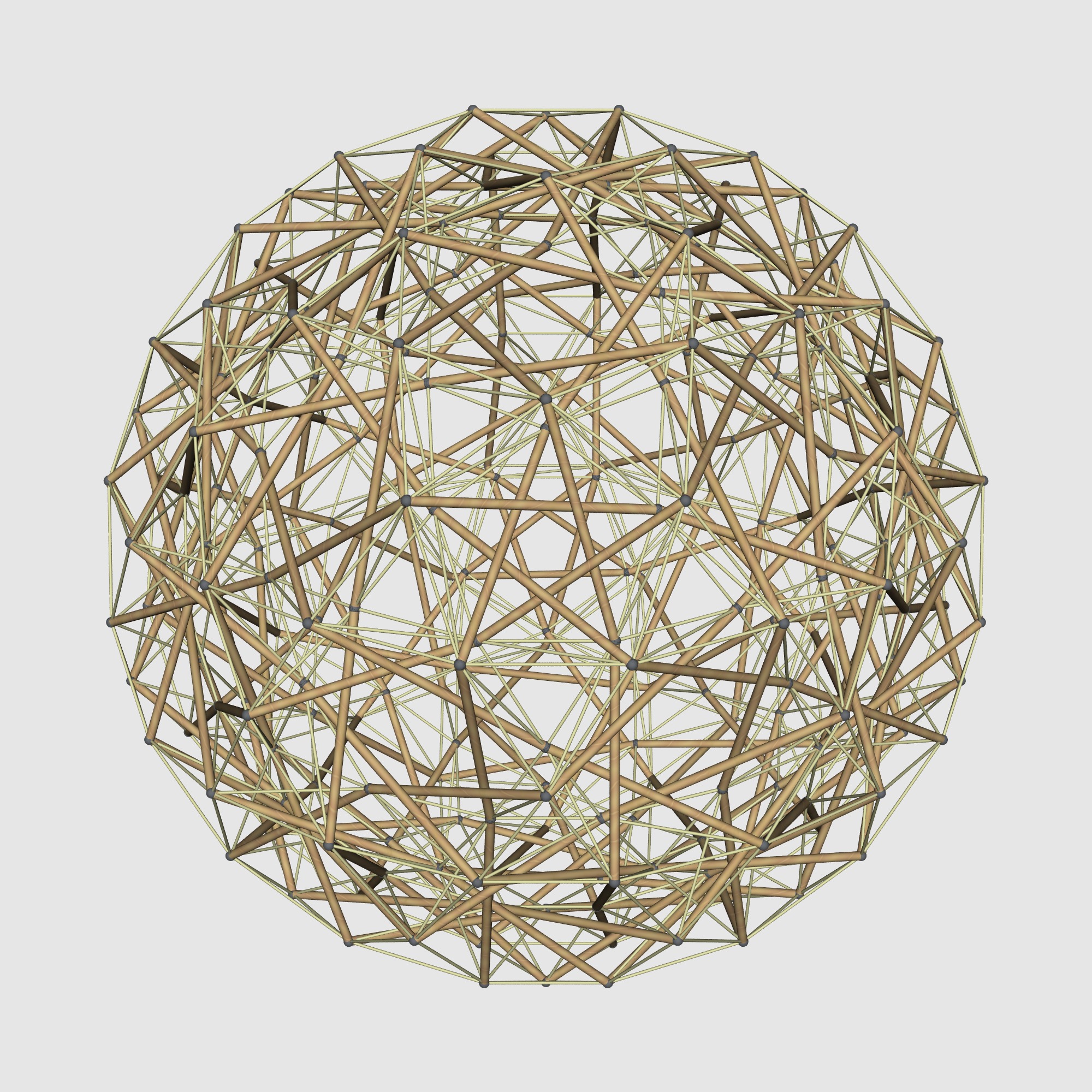
Frequency: 6v
-Taff
TaffGoch
Sep 15, 2016, 1:10:36 AM9/15/16
to Geodesic Help Group
Correctly-corresponding 6v, 3D-modeled:
(Specs to follow....)
-Taff
Tensegrity Wiki
Sep 15, 2016, 1:11:01 AM9/15/16
to geodes...@googlegroups.com
TaffGoch, I hereby inaugurate an annual award for the most complex great-circle geometrical rendering, and bestow it upon your omnidirectional head.
Your ability to visually parse these structures is unsurpassed. --
--
You received this message because you are subscribed to the "Geodesic Help" Google Group
--
To unsubscribe from this group, send email to GeodesicHelp+unsubscribe@googlegroups.com
--
To post to this group, send email to geodes...@googlegroups.com
--
For more options, visit http://groups.google.com/group/geodesichelp?hl=en
---
You received this message because you are subscribed to the Google Groups "Geodesic Help Group" group.
To unsubscribe from this group and stop receiving emails from it, send an email to geodesichelp+unsubscribe@googlegroups.com.
For more options, visit https://groups.google.com/d/optout.
Tensegrity Wiki
Sep 15, 2016, 1:12:17 AM9/15/16
to geodes...@googlegroups.com
I attached to previous the most high res photos I could find of that day.
Hope it helps.--
--
You received this message because you are subscribed to the "Geodesic Help" Google Group
--
To unsubscribe from this group, send email to GeodesicHelp+unsubscribe@googlegroups.com
--
To post to this group, send email to geodes...@googlegroups.com
--
For more options, visit http://groups.google.com/group/geodesichelp?hl=en
---
You received this message because you are subscribed to the Google Groups "Geodesic Help Group" group.
To unsubscribe from this group and stop receiving emails from it, send an email to geodesichelp+unsubscribe@googlegroups.com.
For more options, visit https://groups.google.com/d/optout.
TaffGoch
Sep 15, 2016, 1:16:39 AM9/15/16
to Geodesic Help Group
I'll email tomorrow -- It's after midnight, here...
-Taff

Adrian Rossiter
Sep 15, 2016, 6:35:27 AM9/15/16
to Geodesic Help Group
Hi Taff
On Tue, 13 Sep 2016, TaffGoch wrote:
> One prism, isolated from the model:
Nice modelling.
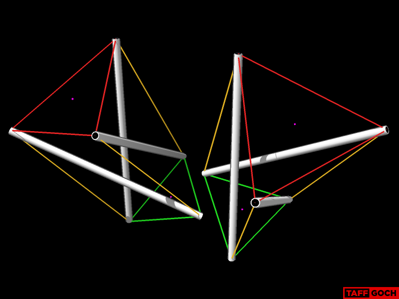
Your prism appears to have the side strings winding in the opposite
direction to the way they are in the photograph.
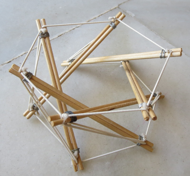
I was interested whether this would be a problem, and made models
of both forms. You can see in the attached photographs that the
original form worked, but with the strings wound as you have
them the prism collapsed.
Adrian.
--
Adrian Rossiter
adr...@antiprism.com
http://antiprism.com/adrian
On Tue, 13 Sep 2016, TaffGoch wrote:
> One prism, isolated from the model:
Your prism appears to have the side strings winding in the opposite
direction to the way they are in the photograph.
I was interested whether this would be a problem, and made models
of both forms. You can see in the attached photographs that the
original form worked, but with the strings wound as you have
them the prism collapsed.
Adrian.
--
Adrian Rossiter
adr...@antiprism.com
http://antiprism.com/adrian
Adrian Rossiter
Sep 15, 2016, 8:38:50 AM9/15/16
to Geodesic Help Group
Hi Taff, TW and All
On Tue, 13 Sep 2016, TaffGoch wrote:
> The Bucky sphere is a tensegrity sphere, *composed of* many adjacent prism
the Antiprism dome_layer program, I have added it in (only 13
lines of code!).
I have attached images showing the result of applying it to a
spherical 3F icosahedron dual (the commands will be valid
for the next snapshot of Antiprism, 23.99+07 or greater). One
is the basic model viewed in Antiview
dome_layer -t prism geo_3_d | antiview -v 0.015
The other is a the model processed by off2pov, with a custom include
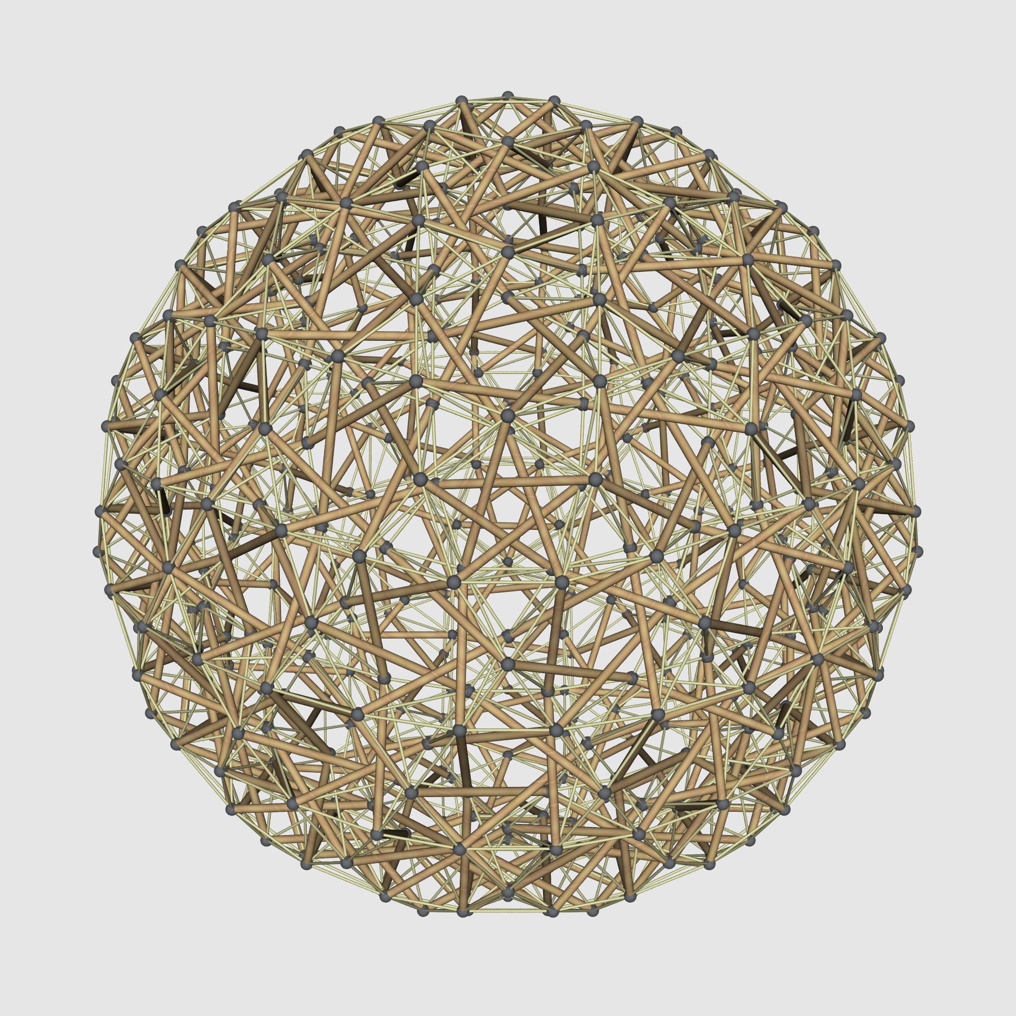
file, and rendered in POV-Ray
off_trans -y D5 geo_3_d | dome_layer -i -t prism | off_color -e M -m map_0:1:1:1 | off2pov -v 0.015 -i tens_strut_string.inc > pri_tens_geo_3_d.pov
[off_trans -y lines up the model on a 5-fold axis. dome_layer -i uses
index numbers for colouring. The off_color command makes the strut
colour 0 and the strings colour 1. off2pov converts it to POV-Ray
format, and the custom include file tens_strut_string.inc (included
below) draws the elements to make the model look like a tensegrity.]
On my system, I rendered this with
povray declare=AspectRatio=1 +a +p +H2000 +W2000 pri_tens_geo_3_d.pov
// tens_strut_string.inc
#include "woods.inc"
#include "metals.inc"
#macro disp_edge(edge, col)
#if(!v_equal(verts[edges[edge][0]], verts[edges[edge][1]]) )
#if (col.x=0)
cylinder{verts[edges[edge][0]] verts[edges[edge][1]] edge_sz
texture{ T_Wood3 }
}
#end
#if (col.x=1)
cylinder{verts[edges[edge][0]] verts[edges[edge][1]] edge_sz/3
texture{pigment{colour <0.8, 0.8, 0.6>}}
}
#end
#end
#end
#macro disp_vertex(vertex, col)
sphere{ verts[vertex] vert_sz texture{T_Chrome_1A pigment{P_Chrome2}}
finish {F_MetalA} }
#end
On Tue, 13 Sep 2016, TaffGoch wrote:
> tensegrties. You can see one, highlighted, here:
As the approximated tensegrity is very like the forms made by
the Antiprism dome_layer program, I have added it in (only 13
lines of code!).
I have attached images showing the result of applying it to a
spherical 3F icosahedron dual (the commands will be valid
for the next snapshot of Antiprism, 23.99+07 or greater). One
is the basic model viewed in Antiview
dome_layer -t prism geo_3_d | antiview -v 0.015
The other is a the model processed by off2pov, with a custom include
file, and rendered in POV-Ray
off_trans -y D5 geo_3_d | dome_layer -i -t prism | off_color -e M -m map_0:1:1:1 | off2pov -v 0.015 -i tens_strut_string.inc > pri_tens_geo_3_d.pov
[off_trans -y lines up the model on a 5-fold axis. dome_layer -i uses
index numbers for colouring. The off_color command makes the strut
colour 0 and the strings colour 1. off2pov converts it to POV-Ray
format, and the custom include file tens_strut_string.inc (included
below) draws the elements to make the model look like a tensegrity.]
On my system, I rendered this with
povray declare=AspectRatio=1 +a +p +H2000 +W2000 pri_tens_geo_3_d.pov
// tens_strut_string.inc
#include "woods.inc"
#include "metals.inc"
#macro disp_edge(edge, col)
#if(!v_equal(verts[edges[edge][0]], verts[edges[edge][1]]) )
#if (col.x=0)
cylinder{verts[edges[edge][0]] verts[edges[edge][1]] edge_sz
texture{ T_Wood3 }
}
#end
#if (col.x=1)
cylinder{verts[edges[edge][0]] verts[edges[edge][1]] edge_sz/3
texture{pigment{colour <0.8, 0.8, 0.6>}}
}
#end
#end
#end
#macro disp_vertex(vertex, col)
sphere{ verts[vertex] vert_sz texture{T_Chrome_1A pigment{P_Chrome2}}
finish {F_MetalA} }
#end
Tensegrity Wiki
Sep 15, 2016, 11:31:07 AM9/15/16
to geodes...@googlegroups.com
Adrian, incredible fast work, thanks for sharing, and great to see antiprism's power at work.
May I repeat a question:--
--
You received this message because you are subscribed to the "Geodesic Help" Google Group
--
To unsubscribe from this group, send email to GeodesicHelp+unsubscribe@googlegroups.com
--
To post to this group, send email to geodes...@googlegroups.com
--
For more options, visit http://groups.google.com/group/geodesichelp?hl=en
--- You received this message because you are subscribed to the Google Groups "Geodesic Help Group" group.
To unsubscribe from this group and stop receiving emails from it, send an email to geodesichelp+unsubscribe@googlegroups.com.
For more options, visit https://groups.google.com/d/optout.
Adrian Rossiter
Sep 15, 2016, 12:24:16 PM9/15/16
to geodes...@googlegroups.com
Hi TW
On Thu, 15 Sep 2016, Tensegrity Wiki wrote:
> Can this be constructed with a continuous tendon or wire?
I believe so. There are six strings meeting at each vertex (where
two struts meet.) Wikipedia says:
https://en.wikipedia.org/wiki/Eulerian_path#Properties
"An undirected graph has an Eulerian cycle if and only if every vertex
has even degree, and all of its vertices with nonzero degree belong to
a single connected component."
> Do you think the model in Bucky's hand has a continuous tendon?
I don't know, but that seems like hard work!
On Thu, 15 Sep 2016, Tensegrity Wiki wrote:
> Can this be constructed with a continuous tendon or wire?
two struts meet.) Wikipedia says:
https://en.wikipedia.org/wiki/Eulerian_path#Properties
"An undirected graph has an Eulerian cycle if and only if every vertex
has even degree, and all of its vertices with nonzero degree belong to
a single connected component."
> Do you think the model in Bucky's hand has a continuous tendon?
TaffGoch
Sep 15, 2016, 4:39:21 PM9/15/16
to Geodesic Help Group
Adrian,
Good eye, regarding the 2 prism images. (I had hoped no one would notice.)
If you take a close look at the other images, you'll see that the tesegrity sphere, itself, IS "wound" correctly.
Only those two "close-ups" are wrong. (Must be my late hours in the dungeon.)
Only those two "close-ups" are wrong. (Must be my late hours in the dungeon.)
-Taff
TaffGoch
Sep 15, 2016, 5:09:19 PM9/15/16
to Geodesic Help Group
What I find interesting is the fact that I couldn't find any (online) information on the Bucky photos, regarding the specs of this tensegrity sphere. Surely, it's documented somewhere, but where? And how limited is access to the details? (I'm sure that it must be, at the very least, buried in the Fuller library-archive boxes.)
Here, within a week, two implementations of the sphere have been accomplished, based on a single question from an online user. So, between 1979 and 2016, no one questioned the photos (or cared enough to pursue it to a satisfactory conclusion?) Has anyone else duplicated the physical model, in the 35+ years?
I find the potential for loss of knowledge/technique disturbing.
Perhaps, now, you have an idea of why I do what I do, and why I started this group. Thanks to all participants who help get such geodesic info documented. (I also expect to see this particular tensegrity covered over at the tensegrity wiki.)
___________________________
___________________________
(Of course, when the internet blows up, or crashes, it's all gone ... again.)
-Taff

Sh Mc
Sep 15, 2016, 6:08:29 PM9/15/16
to geodes...@googlegroups.com
Just spit balling from a snipit of this conversation, but wouldn't the original building permits contain blueprints? If this was required then. I'll delve a bit into it in a few days when I finish my current investigative case load at work.
--
Sh Mc
Sep 15, 2016, 6:09:30 PM9/15/16
to geodes...@googlegroups.com
Wow ment to say patent. Blue print? Wtf was I thinkin.
TaffGoch
Sep 15, 2016, 7:08:55 PM9/15/16
to Geodesic Help Group
TW,
I attempted to replicate the perspective, produced by the camera's field-of-view (FOV,) but was hampered, somewhat, by the fact that the tensegrity sphere in the photo is not precisely spherical, due to construction irregularities. Secondly, I can't tell which subdivision method was used.
Since I used a Mexican-method 6v sphere, I didn't expect everything to match-up, perfectly, as the method had not yet been developed, in that era. Still, it comes pretty close. By "masking" the backside elements of my 3D model, 3D-perception is enhanced, a bit.
The struts in the central region of the photo coincide the best.
-Taff
TaffGoch
Sep 15, 2016, 10:00:18 PM9/15/16
to Geodesic Help Group
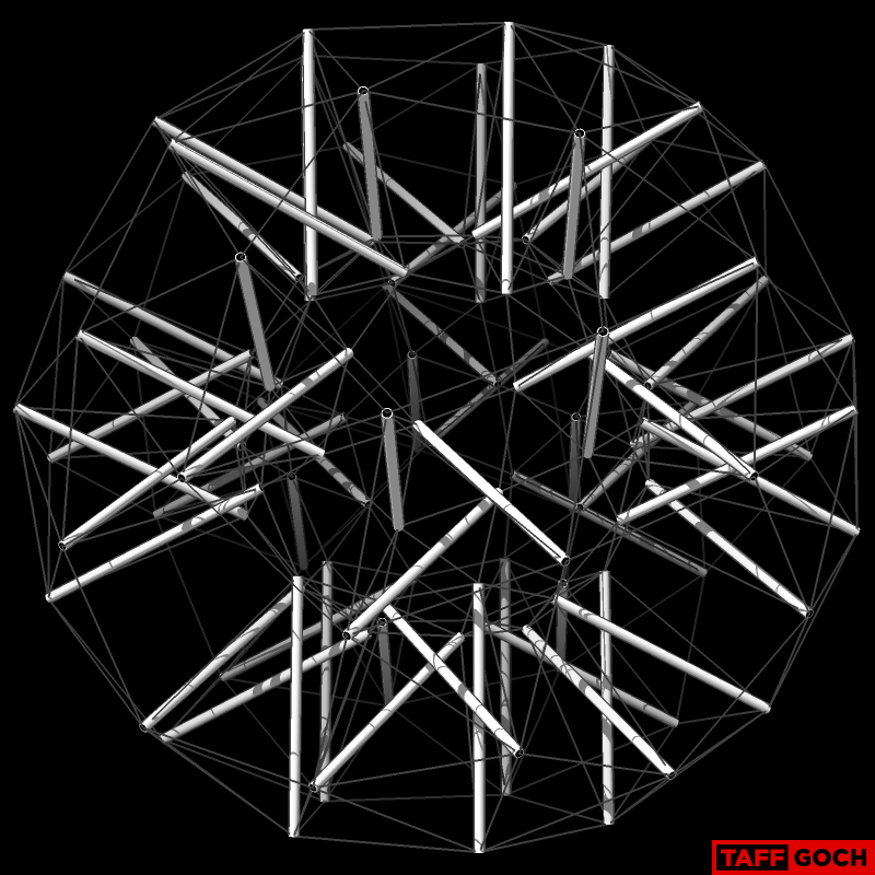
Specs, regarding the 6v tensegrity sphere (photo):
540 struts
80 hexagonal prism tensegrities
12 pentagonal prism tensegrities
The radius of the inner "sphere" of tendons appears to be ~80% of the "outer" tendon-sphere radius.
-Taff
Adrian Rossiter
Sep 16, 2016, 1:24:18 AM9/16/16
to Geodesic Help Group
Hi Taff
On Thu, 15 Sep 2016, TaffGoch wrote:
> The struts in the central region of the photo coincide the best.
Presumably, the original struts are all the same length, which
means that the prism on the pentagons would be aound 5% higher
if they had the same approximate edge length as the hexagons.
In your comparison the photograph does appear to shows the
pentagon with a visibly longer edge (and also twisted slightly).
Adrian
On Thu, 15 Sep 2016, TaffGoch wrote:
> The struts in the central region of the photo coincide the best.
means that the prism on the pentagons would be aound 5% higher
if they had the same approximate edge length as the hexagons.
In your comparison the photograph does appear to shows the
pentagon with a visibly longer edge (and also twisted slightly).
Adrian
Adrian Rossiter
Sep 16, 2016, 1:47:00 AM9/16/16
to Geodesic Help Group
On Fri, 16 Sep 2016, Adrian Rossiter wrote:
> Presumably, the original struts are all the same length, which
> means that the prism on the pentagons would be aound 5% higher
> if they had the same approximate edge length as the hexagons.
That should say around 20% higher! But to have the same height
> Presumably, the original struts are all the same length, which
> means that the prism on the pentagons would be aound 5% higher
> if they had the same approximate edge length as the hexagons.
the pentagon edge only needs to be around 7% longer.
Adrian.
Tensegrity Wiki
Sep 16, 2016, 11:28:48 AM9/16/16
to geodes...@googlegroups.com
Yes, we will document this on the wiki.
Also, the wiki is backed up so if wikispaces disappears I can restore it.--
--
You received this message because you are subscribed to the "Geodesic Help" Google Group
--
To unsubscribe from this group, send email to GeodesicHelp+unsubscribe@googlegroups.com
--
To post to this group, send email to geodes...@googlegroups.com
--
For more options, visit http://groups.google.com/group/geodesichelp?hl=en
--- You received this message because you are subscribed to the Google Groups "Geodesic Help Group" group.
To unsubscribe from this group and stop receiving emails from it, send an email to geodesichelp+unsubscribe@googlegroups.com.
For more options, visit https://groups.google.com/d/optout.
TaffGoch
Sep 16, 2016, 10:14:25 PM9/16/16
to Geodesic Help Group
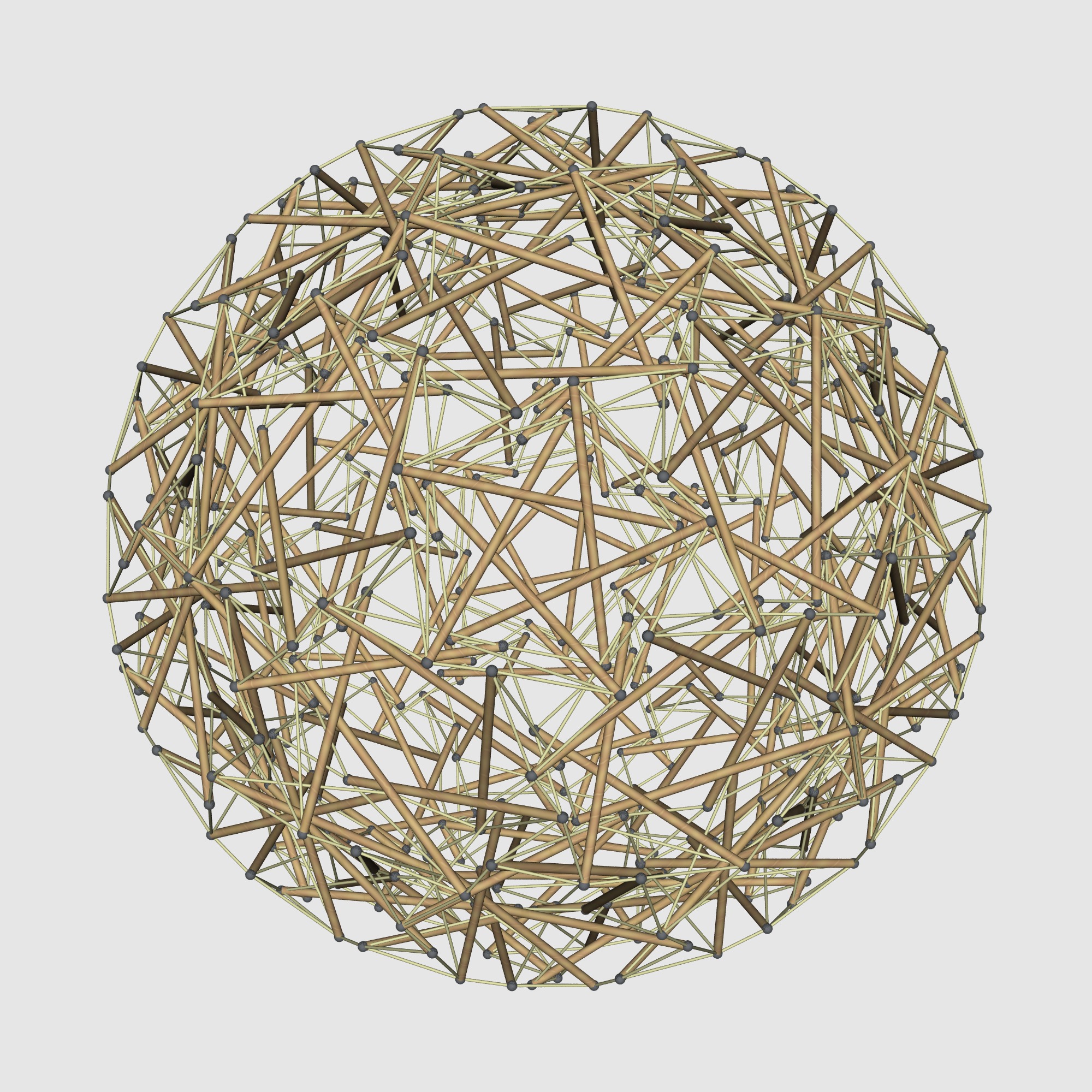
The 6v and 8v tensegrities are rather formidable, and might discourage construction. Here is a 4v tensegrity sphere, which more-readily lends itself to hobby construction:
I've posted this model to the 3D Warehouse, so that interested readers can measure and plan a physical model.
There are 240 struts, 12 pentagonal prism tensegrities, and 30 hexagonal prism tensegrities.
______________________________
______________________________
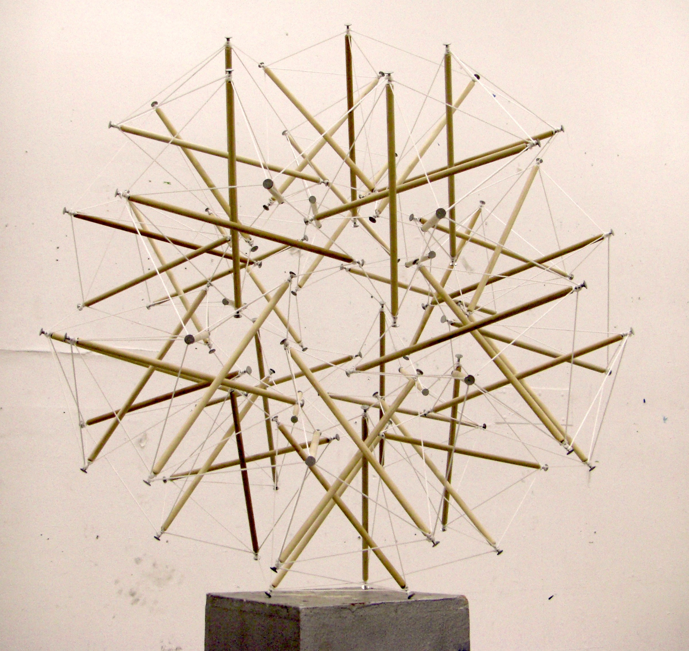
Here's a tensegrity detail that I collected from online, which may inspire:
-Taff
Adrian Rossiter
Sep 17, 2016, 6:52:17 AM9/17/16
to Geodesic Help Group
Hi Taff
On Fri, 16 Sep 2016, TaffGoch wrote:
> Here's a tensegrity detail that I collected from online, which may inspire:
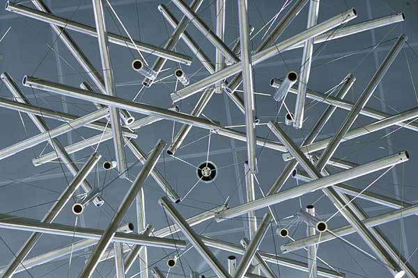
Going by the images here
http://www.publicart.wisc.edu/artists-fuller-sixty-strut-tensegrity-sphere.htm
You can see the struts come in parallel sets of 5 on opposing
sides of the model. In fact, they appear to pass through the
vertices of a snub dodecahedron, parallel to the pentagonal
faces.
What is harder to see is the strings!
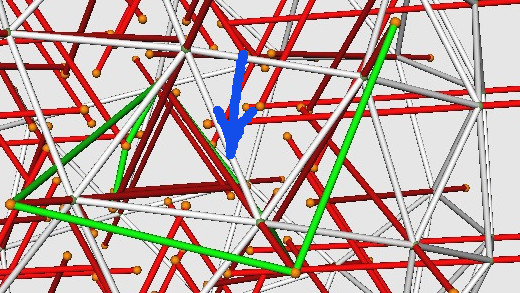
I have attached an image showing how it might be connected. The
strings at the base of a triangular tensegrity prism pass through
another strut, otherwise the base strings from two prisms come
close to having an (ugly) overlap.
I have rendered a view along a 5-fold axis, which you can
see is close to the photograph of the same view.
On Fri, 16 Sep 2016, TaffGoch wrote:
> Here's a tensegrity detail that I collected from online, which may inspire:
http://www.publicart.wisc.edu/artists-fuller-sixty-strut-tensegrity-sphere.htm
You can see the struts come in parallel sets of 5 on opposing
sides of the model. In fact, they appear to pass through the
vertices of a snub dodecahedron, parallel to the pentagonal
faces.
What is harder to see is the strings!
I have attached an image showing how it might be connected. The
strings at the base of a triangular tensegrity prism pass through
another strut, otherwise the base strings from two prisms come
close to having an (ugly) overlap.
I have rendered a view along a 5-fold axis, which you can
see is close to the photograph of the same view.
Adrian Rossiter
Sep 17, 2016, 7:13:31 AM9/17/16
to geodes...@googlegroups.com
Hi TW
On Fri, 16 Sep 2016, Tensegrity Wiki wrote:
> I also was puzzled as to how this tensegrity is not mentioned in any of my
> sources.
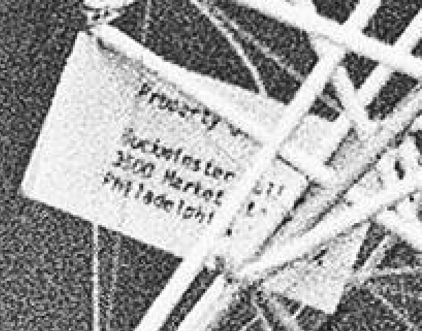
> It does have a tag on it in the photo.
I looked into that as I was trying to attribute the design in the
documentation for the dome_layer program.
You can read some of the label in this photo
http://www-tc.pbs.org/wnet/americanmasters/files/2001/12/BuckminsterFuller.jpg
I don't know what the first line says ("Property"?).
The second line starts "Buckminster"
The third line looks like a address line.
The fourth line starts "Mississippi"
Adrian
On Fri, 16 Sep 2016, Tensegrity Wiki wrote:
> I also was puzzled as to how this tensegrity is not mentioned in any of my
> sources.
> It does have a tag on it in the photo.
documentation for the dome_layer program.
You can read some of the label in this photo
http://www-tc.pbs.org/wnet/americanmasters/files/2001/12/BuckminsterFuller.jpg
I don't know what the first line says ("Property"?).
The second line starts "Buckminster"
The third line looks like a address line.
The fourth line starts "Mississippi"
Adrian
Adrian Rossiter
Sep 17, 2016, 7:20:10 AM9/17/16
to geodes...@googlegroups.com
On Sat, 17 Sep 2016, Adrian Rossiter wrote:
> The fourth line starts "Mississippi"
Or not... Reviewing it again, I don't know what the fourth line says!
> The fourth line starts "Mississippi"
Adrian.
TaffGoch
Sep 17, 2016, 4:44:10 PM9/17/16
to Geodesic Help Group
Adrian,
Property label bears Bucky's address, at the time
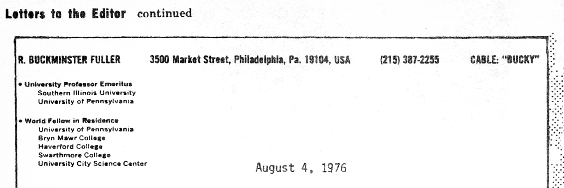
Too bad, the label contained no model spec's.
-Taff
TaffGoch
Sep 17, 2016, 6:16:38 PM9/17/16
to Geodesic Help Group
Adrian,
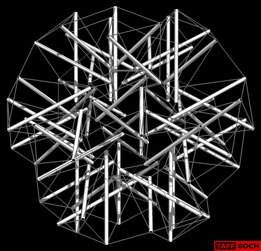
In the article, Buckminster Fuller sculpture installed in new Engineering Centers Building ...
"The structure consists of 20 three-strut tensegrity prisms in an
icosahedral (having 20 faces) form. Sixty tubes radiate outward from the
center of its complex arrangement...."
From this reference, I looked for the triangular prisms:
Confirming your "snub dodecahedron" hypothesis:
(triangular prism outermost edges in red)
-Taff
TaffGoch
Sep 17, 2016, 6:39:56 PM9/17/16
to Geodesic Help Group
This sculpture could have used equivalent lengths for the outermost tendons, which is a defining characteristic of a regular snub-dodecahedron.
(Beats me why the precise geometry wasn't employed.)
(Beats me why the precise geometry wasn't employed.)
-Taff
TaffGoch
Sep 17, 2016, 6:46:49 PM9/17/16
to Geodesic Help Group
Forgot to mention that the struts would all be the same length, as well.
-Taff
TaffGoch
Sep 17, 2016, 7:47:53 PM9/17/16
to Geodesic Help Group
Here's my initial attempt, modeling on a regular snub-dodecahedron:
Note: The inner tendon-sphere radius is 50% the of the outer tendon-sphere radius.
(I find that shadows help with my 3D-visualization -- i.e.; depth-perception.)
-Taff
TaffGoch
Sep 17, 2016, 8:01:52 PM9/17/16
to Geodesic Help Group
Tendon visualization; color assist:
-Taff
TaffGoch
Sep 17, 2016, 10:25:13 PM9/17/16
to Geodesic Help Group
Adrian,
My initial model, using regular snub-dodecahedron geometry for BOTH outer and inner tendons, produces struts that appear too short:
If I relax the constraint for the inner tendons, such that they do NOT conform to regular snub-dodecahedron geometry, I can extend the struts to a longer length, to more-closely conform to the photograph of Bucky's 60-strut sculpture:

-Taff
Adrian Rossiter
Sep 18, 2016, 2:40:05 AM9/18/16
to Geodesic Help Group
Hi Taff
On Sat, 17 Sep 2016, TaffGoch wrote:
> My initial model, using regular snub-dodecahedron geometry for *BOTH* outer
> conform to *regular* snub-dodecahedron geometry, I can extend the struts to
photo I used for comparison you can get a fair idea of the lower
point for the struts. I didn't try too hard on the length, but
the recent photo you posted could help with that.
Also, if you trace around the outside of the sculpture in the photo
you posted you can see that it does not have all the strings that
correspond to a snub dodecahedron's edges.
Regarding the form itself, it requires certain properties, but
especially that you shouldn't be able to shorten the strings
by moving a strut or group of struts. If the struts don't extend
inwards enough then they don't have enough interpenetration and
you can see that one of the tensegrity prisms could likely move,
and so the model would be floppy.
As a generalisation of the form, it has some relation to the
other prism tensegrity sphere. In the earlier one, you take a
polyhedron that has all order-3 vertices, modify it with an
"alternation" operation (creating triangles at the original
vertices), and place tensegrity prisms on the faces corresponding
to the original faces.
The generalisation of the 60-strut form takes a polyhedron (may
not need all order-3 vertices) and modifies it by a "snub"
operation. "prism" tensegrities are aligned with the faces
corrsponding to the original vertices, with struts approximately
perpendicular to the original faces, and connected as per the
60-strut tensegrity.
https://en.wikipedia.org/wiki/Alternation_(geometry)
https://en.wikipedia.org/wiki/Snub_(geometry)
In both cases, this would be considered an approximate start and
the final stable form would still need to be calculated.
The difference between the two forms is that the snubbing operation
separates the tensegrity prisms more, so they need to extend inwards
in order to interpenetrate.
To test the need for order-3 vertices in the snub form, a smaller
model like a "snub octahedron" could be made.
On Sat, 17 Sep 2016, TaffGoch wrote:
> My initial model, using regular snub-dodecahedron geometry for *BOTH* outer
> and inner tendons, produces struts that appear too short:
> [image: Inline image 1]
>
> If I relax the constraint for the inner tendons, such that they do *NOT*
> [image: Inline image 1]
>
> conform to *regular* snub-dodecahedron geometry, I can extend the struts to
> a longer length, to more-closely conform to the photograph of Bucky's
> 60-strut sculpture:
> [image: Inline image 2]
If you view your model along a 5-fold axis and compare it to the
> 60-strut sculpture:
> [image: Inline image 2]
photo I used for comparison you can get a fair idea of the lower
point for the struts. I didn't try too hard on the length, but
the recent photo you posted could help with that.
Also, if you trace around the outside of the sculpture in the photo
you posted you can see that it does not have all the strings that
correspond to a snub dodecahedron's edges.
Regarding the form itself, it requires certain properties, but
especially that you shouldn't be able to shorten the strings
by moving a strut or group of struts. If the struts don't extend
inwards enough then they don't have enough interpenetration and
you can see that one of the tensegrity prisms could likely move,
and so the model would be floppy.
As a generalisation of the form, it has some relation to the
other prism tensegrity sphere. In the earlier one, you take a
polyhedron that has all order-3 vertices, modify it with an
"alternation" operation (creating triangles at the original
vertices), and place tensegrity prisms on the faces corresponding
to the original faces.
The generalisation of the 60-strut form takes a polyhedron (may
not need all order-3 vertices) and modifies it by a "snub"
operation. "prism" tensegrities are aligned with the faces
corrsponding to the original vertices, with struts approximately
perpendicular to the original faces, and connected as per the
60-strut tensegrity.
https://en.wikipedia.org/wiki/Alternation_(geometry)
https://en.wikipedia.org/wiki/Snub_(geometry)
In both cases, this would be considered an approximate start and
the final stable form would still need to be calculated.
The difference between the two forms is that the snubbing operation
separates the tensegrity prisms more, so they need to extend inwards
in order to interpenetrate.
To test the need for order-3 vertices in the snub form, a smaller
model like a "snub octahedron" could be made.
TaffGoch
Sep 18, 2016, 3:36:08 AM9/18/16
to Geodesic Help Group
Adrian,
The more I look at it, the more I think that it requires gravity to provide tension. Look at the suspension points, which are connected to the inside ends of several struts.
If this were to sit on the ground, the result may be something like this:
If this were to sit on the ground, the result may be something like this:
-Taff
Adrian Rossiter
Sep 18, 2016, 4:31:17 AM9/18/16
to Geodesic Help Group
Hi Taff
On Sun, 18 Sep 2016, TaffGoch wrote:
> The more I look at it, the more I think that it requires gravity to provide
> tension. Look at the suspension points, which are connected to the inside
> ends of several struts.
It is possible. I don't have enough elastic around to make a quick
replica with my barbecue stick struts to test it, but I will see if
I can get some next week.
It is difficult to judge, but looking at the explanation model I
posted earlier, with the example green strings, I think that if you
push in a triangular prism the inner short strings would lengthen.
This would allow the unhung sculpture to naturally resist an external
inwards force.
On Sun, 18 Sep 2016, TaffGoch wrote:
> The more I look at it, the more I think that it requires gravity to provide
> tension. Look at the suspension points, which are connected to the inside
> ends of several struts.
replica with my barbecue stick struts to test it, but I will see if
I can get some next week.
It is difficult to judge, but looking at the explanation model I
posted earlier, with the example green strings, I think that if you
push in a triangular prism the inner short strings would lengthen.
This would allow the unhung sculpture to naturally resist an external
inwards force.
Adrian Rossiter
Sep 18, 2016, 4:42:55 AM9/18/16
to Geodesic Help Group
Hi Taff
On Sun, 18 Sep 2016, Adrian Rossiter wrote:
> It is difficult to judge, but looking at the explanation model I
> posted earlier, with the example green strings, I think that if you
> push in a triangular prism the inner short strings would lengthen.
> This would allow the unhung sculpture to naturally resist an external
> inwards force.
The basic thought is that you have prisms dropping on axes and
their inner vertices are connected by strings. When they are far out
a small drop makes the strings looser, however as they get closer
to the centre, and overlap, eventually a drop makes the string
longer. The prisms could counter this by rotating, but if there
are other strings to oppose the rotation then there is a potential
for tension to be preserved.
On Sun, 18 Sep 2016, Adrian Rossiter wrote:
> It is difficult to judge, but looking at the explanation model I
> posted earlier, with the example green strings, I think that if you
> push in a triangular prism the inner short strings would lengthen.
> This would allow the unhung sculpture to naturally resist an external
> inwards force.
their inner vertices are connected by strings. When they are far out
a small drop makes the strings looser, however as they get closer
to the centre, and overlap, eventually a drop makes the string
longer. The prisms could counter this by rotating, but if there
are other strings to oppose the rotation then there is a potential
for tension to be preserved.
TaffGoch
Sep 18, 2016, 3:56:45 PM9/18/16
to Geodesic Help Group
Ahh, but, what if ALL prisms move inward? That is countered in the original tensegrity-of-discussion, due to shared vertices of adjacent strut-ends (compression-element contact.)
No such physical compression-element relationship exists in this snub tensegrity sculpture.
No such physical compression-element relationship exists in this snub tensegrity sculpture.
Still scratchin' my head,...
-Taff
TaffGoch
Sep 18, 2016, 7:27:16 PM9/18/16
to Geodesic Help Group
New tensegrity, composed of 30 triangular compression elements, and icosidodecahedron-edge tendons:
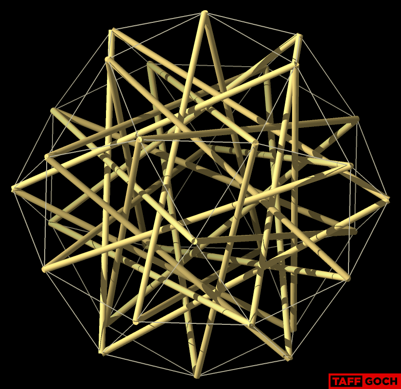
I recalled seeing a photo of this one, in Bucky's hands, but, now, can't find it.
The only "triangle" tensegrity photo that I could find was this one:

The only "triangle" tensegrity photo that I could find was this one:
Recollection wrong?
-Taff
TaffGoch
Sep 18, 2016, 7:49:27 PM9/18/16
to Geodesic Help Group
Correction: Not 30 triangles, but 30 struts (10 triangles)
-Taff
Adrian Rossiter
Sep 19, 2016, 2:59:49 AM9/19/16
to Geodesic Help Group
Hi Taff
On Sun, 18 Sep 2016, TaffGoch wrote:
> Ahh, but, what if *ALL* prisms move inward?
It is the same if they all move slightly inwards (but there may be some
more complex movement that makes the model floppy.)
> That is countered in the
> original tensegrity-of-discussion, due to shared vertices of adjacent
> strut-ends *(compression-element contact.)*
that the prisms could be twisted out of the "deresonated" form to make a
tensegrity with no contact points. I have attached an image to show an
example twist (noting that, besides the twist "angle", there seem to be
some other choices leading to a variety of final forms).
On Sun, 18 Sep 2016, TaffGoch wrote:
> Ahh, but, what if *ALL* prisms move inward?
It is the same if they all move slightly inwards (but there may be some
more complex movement that makes the model floppy.)
> That is countered in the
> original tensegrity-of-discussion, due to shared vertices of adjacent
>
> No such physical compression-element relationship exists in this snub
> tensegrity sculpture.
In the first model the connections points are not rigid and it is possible
> No such physical compression-element relationship exists in this snub
> tensegrity sculpture.
that the prisms could be twisted out of the "deresonated" form to make a
tensegrity with no contact points. I have attached an image to show an
example twist (noting that, besides the twist "angle", there seem to be
some other choices leading to a variety of final forms).
TaffGoch
Sep 21, 2016, 7:47:34 PM9/21/16
to Geodesic Help Group
Okay, I've done some more digging, and found out how the prisms in Bucky's "60-strut tensegrity sculpture" are stabilized, to prevent expansion or contraction. (I.e.; how the sphere rigidity is maintained.)
Again, here's what we're discussing:

Each of the 20 afore-mentioned prisms looks like this:
Rotating this prism into position, so that the outer (red) triangle is coincident with a snub-dodecahedron face, as described/depicted in previous posts:

Adding an adjacent prism, coincident with another snub-dodecahedron-face triangle:
In this relationship, either, or both prisms are internally rigid, but each prism is not "fixed" in position, relative to an adjacent prism. Either can move inwards or outwards, relative to the center of the sphere. Merely connecting two prisms with additional tendon(s) will poorly limit motion. Neither prism is "fixed" in position -- only limited, a bit.
However, if we modify the green tendons (rather than adding tendons,) the prisms become intimately-connected:

Due to tension in the green tendons, the inward displacement of both prisms is limited to the elasticity of the tendons. If non-tensile cables are used for the tendons, no (or very little) displacement is possible. The bottom (innermost) edges of the rigid prisms are now connected, rigidly, themselves. They can no longer displace, relative to each other, nor relative to the entire sphere. You can think of the prisms as "solid" objects, now connected at their bottom (innermost) edges.
Outward displacement is, of course, restricted by additional outer, red, tendons, but that is obvious, and did not cause any confusion for me (and, I assume, other readers.)
_______________________
_______________________
I posted the above images, because I don't know if the attached AVI animation will display properly for everyone.
-Taff
TaffGoch
Sep 21, 2016, 10:53:43 PM9/21/16
to Geodesic Help Group
"Striptease" animation:
(Hopefully, not much "tease" left, after this stripping. All clear, now?)
-Taff
TaffGoch
Sep 22, 2016, 12:01:06 AM9/22/16
to Geodesic Help Group
-Taff
Adrian Rossiter
Sep 22, 2016, 3:38:11 AM9/22/16
to Geodesic Help Group
Hi Taff
On Wed, 21 Sep 2016, TaffGoch wrote:
> Serendipitous discovery: *Calling Ball
> <http://jeremysarchet.com/2008/01/17/calling-ball/>*
The stringing of this matches the stringing I originally posted in my
explanation image. Except... my full models appear to have some extra
strings on the inside! Reviewing my original image I have just noticed
there is a rogue string hidden behind the others (you can see just a
hint of green where the arrow points).
I have also been thinking about the 60-strut model, and how its type is
related to the type of the first model by twisting.
I have written a programm to model this twisting and, interestingly, the
external strings of the 60-strut model are wired similarly to a twisted
dodecahedron model (pentagonal tensegrity prisms on a dodecahedron).
I have currently only modelled one twisting possibility. In the original
"deresonated" model a twist can split touching strut ends on two paths,
each with two sense directions, allowing for 16 kinds of model (assuming
they work, but it is looking like that many of them will), or 8 if you
consider a "left-right" twist parameter to make the same kind of model.
If you look at the stringing of the 60-strut tensegrity you will see that
the outer strings are connected like a zig-zag tensegrity dodecahedron
(but more closed), and the inner strings like a zig-zag tensegrity
icosahedron.
http://www.antiprism.com/album/835_tens_models/tens_30_Lrg.jpg.9.html
http://www.antiprism.com/album/835_tens_models/tens_30c_Lrg.jpg.7.html
This suggests a view that it could start as a dodecahedron prism
tensegrity sphere, and the inside and outside prism ends are twisted in
opposite directions on the string paths until the prism struts are
parallel (in sets of five).
When I have added the other twisting options to my program I will check
this.
Adrian Rossiter
Sep 22, 2016, 8:16:10 AM9/22/16
to Geodesic Help Group
On Thu, 22 Sep 2016, Adrian Rossiter wrote:
> I have currently only modelled one twisting possibility. In the original
> "deresonated" model a twist can split touching strut ends on two paths, each
> with two sense directions,
Either of the two paths produce a similar model, connected the same way.
> I have currently only modelled one twisting possibility. In the original
> "deresonated" model a twist can split touching strut ends on two paths, each
> with two sense directions,
In which case, probably all that is needed to produce illustrative models
is two independent twist parameters - one for the top layer and one for
the bottom.
Adrian Rossiter
Sep 22, 2016, 1:00:23 PM9/22/16
to Geodesic Help Group
On Thu, 22 Sep 2016, Adrian Rossiter wrote:
> If you look at the stringing of the 60-strut tensegrity you will see that the
> outer strings are connected like a zig-zag tensegrity dodecahedron (but more
> closed), and the inner strings like a zig-zag tensegrity icosahedron.
>
> http://www.antiprism.com/album/835_tens_models/tens_30_Lrg.jpg.9.html
> http://www.antiprism.com/album/835_tens_models/tens_30c_Lrg.jpg.7.html
>
> This suggests a view that it could start as a dodecahedron prism tensegrity
> sphere, and the inside and outside prism ends are twisted in opposite
> directions on the string paths until the prism struts are parallel (in sets
> of five).
>
> When I have added the other twisting options to my program I will check this.
By twisting both ways it is possible to make similar tensegrity models for
> If you look at the stringing of the 60-strut tensegrity you will see that the
> outer strings are connected like a zig-zag tensegrity dodecahedron (but more
> closed), and the inner strings like a zig-zag tensegrity icosahedron.
>
> http://www.antiprism.com/album/835_tens_models/tens_30_Lrg.jpg.9.html
> http://www.antiprism.com/album/835_tens_models/tens_30c_Lrg.jpg.7.html
>
> This suggests a view that it could start as a dodecahedron prism tensegrity
> sphere, and the inside and outside prism ends are twisted in opposite
> directions on the string paths until the prism struts are parallel (in sets
> of five).
>
> When I have added the other twisting options to my program I will check this.
both icosahedron and dodecahedron base models. I have attached an image
showing these, with dodecahedron on the left and icosahedron on the right.
However, these models differ in the strings that connect the layers. In
particular, the struts and these strings form a loop in each prism, and so
the two models are necessarily different. The 60-strut tensegrity
corresponds to the icosahedron base.
For interest I have attached images of models based on an F2 geodesic
sphere dual, with the prisms: unturned, both ends turned the same way, and
both ends turned different ways.
I have also attached the program code (for reference only.)
TaffGoch
Sep 22, 2016, 4:28:11 PM9/22/16
to Geodesic Help Group
Adrian,
I noted the chirality of the prisms, and that of the sphere geometry, and how, combined, they could result in (at least) four different versions. I didn't consider the outer, adjoining tendon "end-swap" possibility. Rigidity investigation would be an interesting build exercise (albeit, time-consuming.)
At the time, I didn't bring up chirality, for fear of "muddying the waters." Since tension/rigidity is (or should be) now clear, It would be of interest to hear your results, if you proceed, on course.
_____________________
At the time, I didn't bring up chirality, for fear of "muddying the waters." Since tension/rigidity is (or should be) now clear, It would be of interest to hear your results, if you proceed, on course.
_____________________
Personally, I'm going to check on the price of some closet-rod covers that I noticed, last month, at the local big-box store. If they are reasonably-priced, they would make excellent struts, as they were light-weight metal, in chrome and yellow-chrome. Crossing my fingers....
-Taff
TaffGoch
Sep 22, 2016, 6:57:01 PM9/22/16
to Geodesic Help Group
I modified my model, to remove certain outer tendons that do not exist in Bucky's original sculpture (as noted by Adrian.) I also rotated the model, to approximate the perspective of the photo taken at the Carl Solway Gallery:

For interested readers, the 3D SketchUp model is now available at the 3D Warehouse:
Bucky's "Sixty Strut Tensegrity Sphere"
Bucky's "Sixty Strut Tensegrity Sphere"
-Taff
TaffGoch
Sep 26, 2016, 7:25:16 PM9/26/16
to Geodesic Help Group
For those readers who are saving photos for a personal "library," I found another photo of Bucky's sculpture, at the University of Wisconsin:
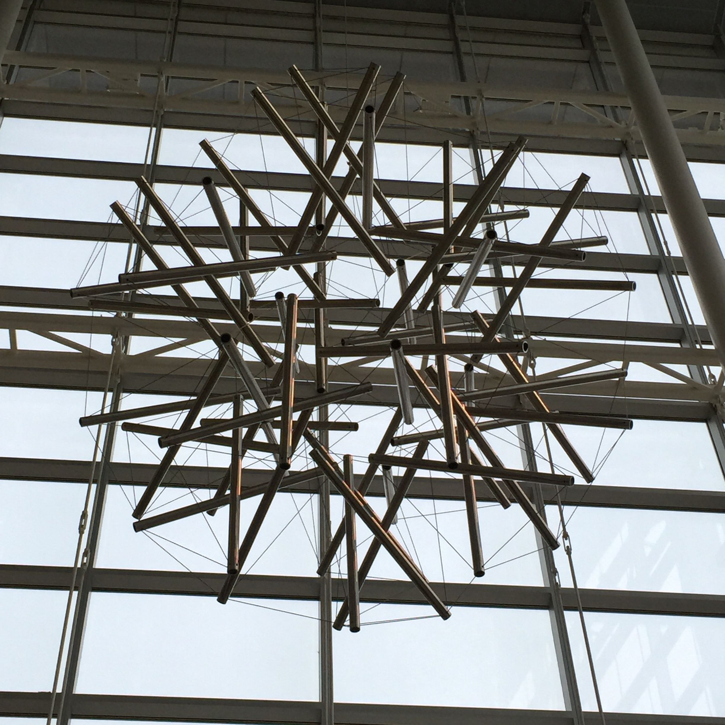
It's a large-scale photo, showing the cables very nicely.
-Taff
TaffGoch
Sep 28, 2016, 7:41:15 PM9/28/16
to Geodesic Help Group
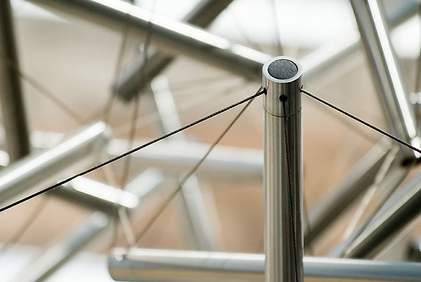
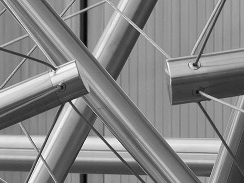
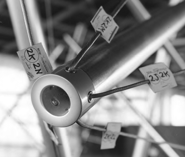
The close-up of the ends of Bucky's sculpture...

...lead me to question how the cable ends are secured.
...lead me to question how the cable ends are secured.
I noted that the holes for the cable ends have a grommet, just like those you can see on Snelson's tensegrity sculptures:
I found revealing details in Snelson's notes:
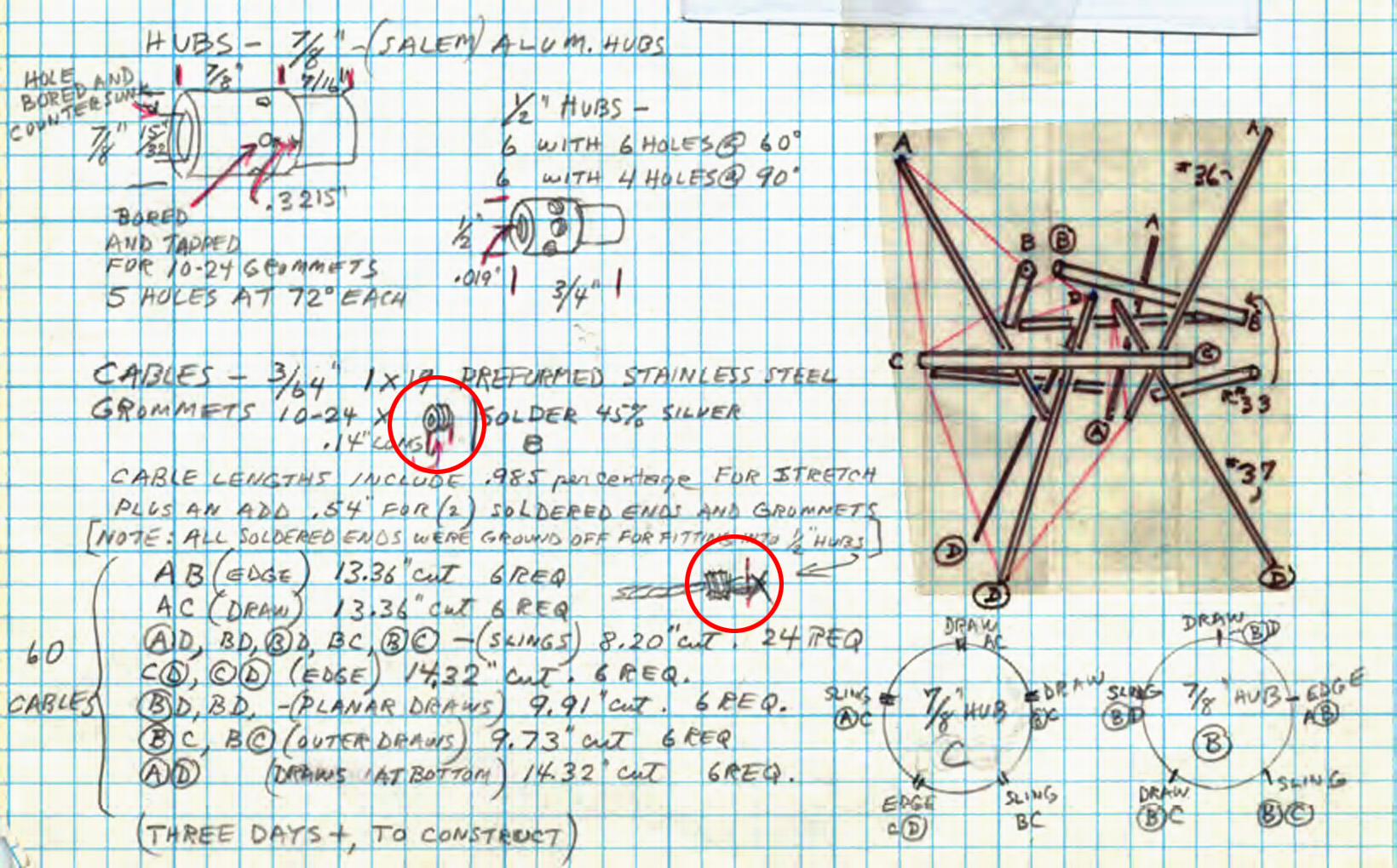
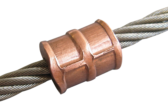
The grommets are threaded, and the holes in the strut end caps are tapped to accept. The grommet is slipped onto the cable, and the end of the cable is then soldered to form a ball that won't slip through the grommet hole -- a "plug" if you like. Early designs included an additional "nicopress" crimp fitting, to serve as the plug:
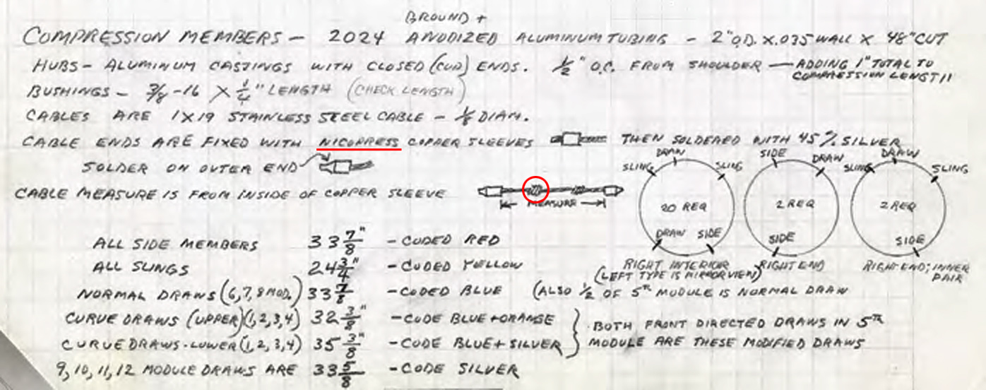
"Nicopress" copper swage fitting:
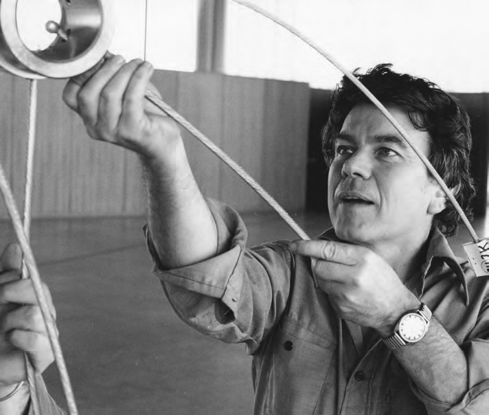
Here's a photo of Kenneth Snelson fabricating a cable:
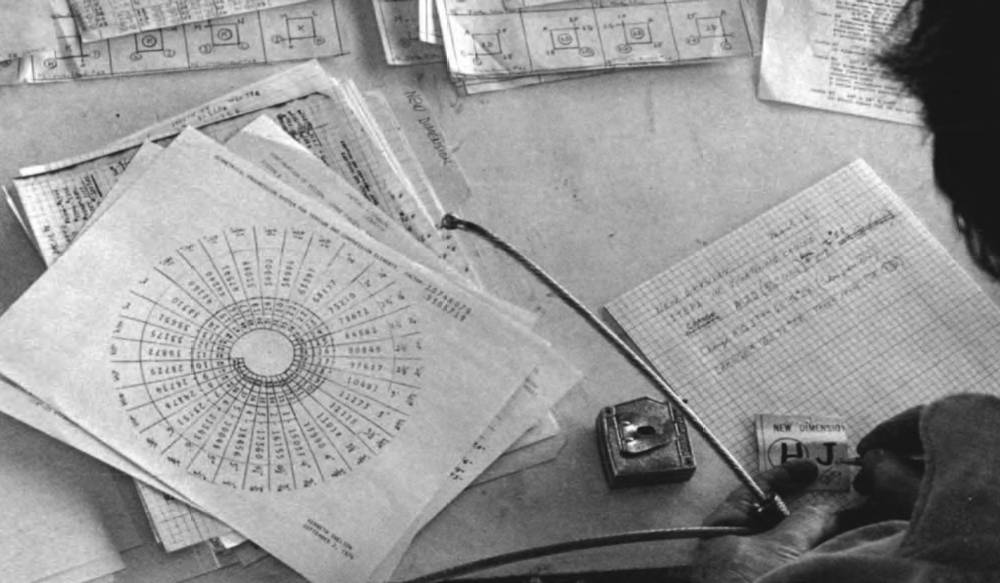
You can see the soldered ball plug on the end, and a threaded grommet near his thumb.
Here's an assembly photo, clearly depicting the solder plug:
I photoshopped this photo, to lighten/enhance the interior of a hub, showing a cable plug, as installed:
Snelson is, obviously, very precise in calculating the lengths of the cables, compensating for the amount of stretch inherent to the wire rope. In several installation/assembly photos, he can be seen using a "come-along" to draw strut ends close enough together, to permit threading-in the grommets.
Now you know, whether you were curious, or not....
-Taff
Tensegrity Wiki
Sep 29, 2016, 4:47:51 AM9/29/16
to geodes...@googlegroups.com
Snelson often spoke about the incredibly high tension and pre-stress load, in fact he thought these made tensegrity impractical for everyday use.
Are these swages and solder plugs able to bear that tension?BTW, Very important clarifications, thanks on behalf of tensegrity researchers everywhere.
Implied by what you write, making it explicit:
The grommet is to reduce wear on the cable at the point of inflection.
--
--
You received this message because you are subscribed to the "Geodesic Help" Google Group
--
To unsubscribe from this group, send email to GeodesicHelp+unsubscribe@googlegroups.com
--
To post to this group, send email to geodes...@googlegroups.com
--
For more options, visit http://groups.google.com/group/geodesichelp?hl=en
---
You received this message because you are subscribed to the Google Groups "Geodesic Help Group" group.
To unsubscribe from this group and stop receiving emails from it, send an email to geodesichelp+unsubscribe@googlegroups.com.
For more options, visit https://groups.google.com/d/optout.
--

biagiodicarlo
Sep 29, 2016, 8:46:41 AM9/29/16
to geodes...@googlegroups.com
Dear Taff,
tank you very much for all the infos.
- Biagio
Il giorno 29 set 2016, alle ore 10:47, Tensegrity Wiki <tensegr...@gmail.com> ha scritto:
Snelson often spoke about the incredibly high tension and pre-stress load, in fact he thought these made tensegrity impractical for everyday use.Are these swages and solder plugs able to bear that tension?
BTW, Very important clarifications, thanks on behalf of tensegrity researchers everywhere.Implied by what you write, making it explicit:The grommet is to reduce wear on the cable at the point of inflection.
On Thu, Sep 29, 2016 at 2:41 AM, TaffGoch <taff...@gmail.com> wrote:
The close-up of the ends of Bucky's sculpture...
<ENGI_Fuller_sculpt07_3072.jpg>
...lead me to question how the cable ends are secured.
I noted that the holes for the cable ends have a grommet, just like those you can see on Snelson's tensegrity sculptures:
<Snelson hub closeup.jpg>
I found revealing details in Snelson's notes:
<Snelson fabrication notes.jpg>
The grommets are threaded, and the holes in the strut end caps are tapped to accept. The grommet is slipped onto the cable, and the end of the cable is then soldered to form a ball that won't slip through the grommet hole -- a "plug" if you like. Early designs included an additional "nicopress" crimp fitting, to serve as the plug:
<Snelson fabrication notes 2.jpg>"Nicopress" copper swage fitting:<Nicopress.png>
Here's a photo of Kenneth Snelson fabricating a cable:
<Snelson fabrication.png>
You can see the soldered ball plug on the end, and a threaded grommet near his thumb.
Here's an assembly photo, clearly depicting the solder plug:
<Snelson install.png>
I photoshopped this photo, to lighten/enhance the interior of a hub, showing a cable plug, as installed:
<Snelson hub peek.jpg>
Snelson is, obviously, very precise in calculating the lengths of the cables, compensating for the amount of stretch inherent to the wire rope. In several installation/assembly photos, he can be seen using a "come-along" to draw strut ends close enough together, to permit threading-in the grommets.Now you know, whether you were curious, or not....-Taff
--
--
You received this message because you are subscribed to the "Geodesic Help" Google Group
--
To unsubscribe from this group, send email to GeodesicHelp+unsubscribe@googlegroups.com
--
To post to this group, send email to geodes...@googlegroups.com
--
For more options, visit http://groups.google.com/group/geodesichelp?hl=en
---
You received this message because you are subscribed to the Google Groups "Geodesic Help Group" group.
To unsubscribe from this group and stop receiving emails from it, send an email to geodesichelp+unsubscribe@googlegroups.com.
For more options, visit https://groups.google.com/d/optout.
--
--
You received this message because you are subscribed to the "Geodesic Help" Google Group
--
To unsubscribe from this group, send email to GeodesicHelp...@googlegroups.com
--
To post to this group, send email to geodes...@googlegroups.com
--
For more options, visit http://groups.google.com/group/geodesichelp?hl=en
---
You received this message because you are subscribed to the Google Groups "Geodesic Help Group" group.
To unsubscribe from this group and stop receiving emails from it, send an email to geodesichelp...@googlegroups.com.
TaffGoch
Sep 29, 2016, 6:53:01 PM9/29/16
to Geodesic Help Group
Tensegrity Wiki wrote:
"The grommet is to reduce wear on the cable at the point of inflection."
_____________________
The grommet, being threaded, and the soldered-plug bearing against the grommet, indicates that the grommet serves as the cable attachment "anchor" to the strut (the strut hub being threaded to receive the grommet.)
The grommet, being threaded, and the soldered-plug bearing against the grommet, indicates that the grommet serves as the cable attachment "anchor" to the strut (the strut hub being threaded to receive the grommet.)
The soldered "plug" is small enough to fit through the threaded hole in the hub, but too large to fit through the hole in the grommet.
The grommet serves primarily as the anchor, not, simply, to reduce wear. My apologies, for the ambiguity.
-Taff
TaffGoch
Sep 29, 2016, 7:08:07 PM9/29/16
to Geodesic Help Group
Tensegrity Wiki wrote:
Are these swages and solder plugs able to bear that tension?
____________________
I think that Snelson must have questioned this, as well, so using both may have been his "belt and suspenders" appoach.
I do note that he was very specific -- requiring "45% silver solder," which is much harder than conventional, commonly-employed solder.
-Taff
I think that Snelson must have questioned this, as well, so using both may have been his "belt and suspenders" appoach.
I do note that he was very specific -- requiring "45% silver solder," which is much harder than conventional, commonly-employed solder.
-Taff
Message has been deleted
Tensegrity Wiki
May 7, 2017, 8:00:07 AM5/7/17
to geodes...@googlegroups.com
Just found Arthur L on grasshopper exploring this same structure...
Maybe you already ran into him:On Sat, Oct 22, 2016 at 9:04 AM, Ashok Mathur <ashokch...@gmail.com> wrote:
New Topic Animated Gifs of Jap JoineryDear All,Even though this is off-topic, I am sure that some us will find it interesting.The techniques and the animated gifs are awesome
http://architizer.com/blog/japanese-art-of-wood-joinery/?utm_medium=email&utm_source=marketo&utm_campaign=core-newsletter-daily-template&utm_content=10192016&mkt_tok=eyJpIjoiTWprMk5UVmtPV00wTURobSIsInQiOiJaQWN0cmpvbkhzOHVvd1VoV0JLN0MzQ1ZWVkhCNDhyNkhXMEFiTzZ0M3RjXC9ianMyMVdGT0xqNVd5YWFDOVwvaVBcL0U0MzhESjVPamw4RldjR1JaalZWemZjVldycXpRQWFzTVUwSDZQV1NuYz0ifQ%3D%3DRegardsAshokRegards
Ashok
--

Tim Wessels
Feb 11, 2018, 2:30:48 PM2/11/18
to Geodesic Help Group
Well, I worked on the fabrication of this spherical stainless steel tensegrity sculpture while I was employed in Bucky's Philadelphia office in 1979. I worked on this project with Rob Grip, Peter Kent, and Chris Kitrick who also worked in Bucky's office. We assembled the sculpture in Philadelphia before taking it (unassembled) to a bank in Dayton, Ohio. It was assembled and suspended from the ceiling over the public banking area which had a high ceiling similar to what you see at the University of Wisconsin Engineering school where the sculpture is currently located.
All of the stainless steel cables had ball shank terminals swaged onto them. The stainless steel end cap holes were drilled using jigs and fixtures we built for the purpose. We fabricated a small rectangular metal "clip" that was notched and bent to match the inside curvature of the stainless steel end caps. These steel clips keep the swaged ball shank terminated cables from coming out through the holes drilled in the end caps We used a small piece of double-sided foam tape adhesive to keep the clips in place when the sculpture was being assembled. One end of each stainless steel end cap was machined or turned to allow it to slip to a certain depth inside the end of the stainless tubes. The stainless steel tubes are much thinner than the stainless steel end caps. This makes the sculpture much lighter in weight.
The end caps were "plugged" with round pieces cut from Rubatex foam insulation sheets. The Rubatex plugs were cut slightly larger than the opening in the end caps which permitted a friction fit to keep them falling out of the end caps. The Rubatex "plugs" prevent dirt or debris from getting into the stainless steel tubes, and it obscures a visual inspection of the method used to secure the cables to the end caps.
The method used for the end cap cable connection was load tested by an engineering lab at the University of Pennsylvania. I have the drilling jigs, and some rejected stainless steel end caps stored in my basement.
BTW, there is one tube in the sculpture that bears the signature of Buckminster Fuller etched into it.
tim wessels
Reply all
Reply to author
Forward
0 new messages