Re: 12' plywood hex dome with flat base (4V class II) made from 6 sheets of underlayment. Photos and pattern. What do you think of hex domes?

Dick Fischbeck
On Thursday, August 13, 2015 at 4:15:23 PM UTC-4, Robert Clark wrote:
This spring I built this 12 foot diameter dome, 8 foot high in the center.

Ken G. Brown
On Aug 13, 2015, at 14:15, Robert Clark <clark.rob...@gmail.com> wrote:
This spring I built this 12 foot diameter dome, 8 foot high in the center.
--
--
You received this message because you are subscribed to the "Geodesic Help" Google Group
--
To unsubscribe from this group, send email to GeodesicHelp...@googlegroups.com
--
To post to this group, send email to geodes...@googlegroups.com
--
For more options, visit http://groups.google.com/group/geodesichelp?hl=en
---
You received this message because you are subscribed to the Google Groups "Geodesic Help Group" group.
To unsubscribe from this group and stop receiving emails from it, send an email to geodesichelp...@googlegroups.com.
For more options, visit https://groups.google.com/d/optout.
<plywood dome 4V class II - COLOR.JPG><dome parts nesting pattern.JPG><CAM00137 (2).jpg><CAM00141 (1).jpg><CAM00145 (1).jpg><CAM00138 (1).jpg>

TaffGoch

TaffGoch
Ken G. Brown
Ken,
I think you're asking what it would look like with all the holes filled in? The shape is based on a 4V class II geodesic sphere which I've attached here. I essentially removed the corners of all the triangular panels. Then, I played with the lengths of the red and blue pieces so that it would have a flat base.I also made a modified version that only uses 2 unique panels (3 if you don't count flipping or mirroring). It's the pink and grey model I've attached. This would also make a pretty cool flyeye dome.-Rob in Massachusetts
<4V class II - 240 sided geodesic.jpg>
<plywood dome - 4V class II - 2 panel.JPG>
<4v class II dome.JPG>
<new flyeye dome 4V class II - 02.JPG>
Ken G. Brown
Ken,
I see what you're saying now. It would be a lot of really odd quirky looking pieces. But, as long as the bolt holes are in the proper places and the pieces can still flex without any buckling, then I guess it would still work. And, almost no waste plywood would be left over.- Rob

Scott Ihrig
Robert - I recently built a 10ft diameter 3v geo dome from ripped 2x4's. Been nuts over domes for a long time and I finally built one. I absolutely love yours. Wish I could build one like it. Awesome job!

Scott Ihrig
On Saturday, August 15, 2015 at 8:59:16 PM UTC-5, Robert Clark wrote:
No, it's cut with a CNC router using my supplied dxf files. I used an online nesting program to lay the pieces out on the plywood as compactly as possible. I had to really search on Craigslist to find someone that does CNC routering. I live in Massachusetts and the CNC guy was in Connecticut - a 2 hour drive. He charged $50 per plywood sheet and it required 6 sheets. I ordered the bolts from McMaster-Carr. All in all the dome cost about $500 labor and materials.If I do another dome, I want to find a place that laser cuts the plywood.- Rob
Dick Fischbeck

Jamie Meredith
- Can the width of the pieces be made less and still maintain structural integrity? I am thinking about how to maximize light to the inside of the dome.
- How would I go about making the dome larger in diameter? I need three dome sizes - 12', 18' and 24'
- Would you be interested in contracting to supply the cut files for the larger versions?
- Could one bolt be used for the connections rather than two?
On Thursday, August 20, 2015 at 9:52:19 AM UTC-5, Robert Clark wrote:
Scott,Your dome picture is awesome. It's exactly what I'm hoping to do with my plywood dome.I've attached the dxf file and an image of the parts list for hardware that I ordered from McMaster-Carr. The plywood I used was 7/32" birch plywood underlayment from Home Depot. You'll need 6 sheets to complete the dome (with a few extra pieces left over). There are notches in some of the pieces to identify which piece is which. I think you can use slightly thicker plywood for a stiffer dome. If you can't get someone to CNC the parts I guess you can use a bandsaw. The important thing is getting the holes in the exact locations.The pieces with 2 notches are the red pieces in the cad image and the pieces with just one notch are the grey. The notch in one piece will always mate with the notch in another piece. Good luck and post pictures of your progress.- Rob

homespun
Jamie Meredith
- Any chance you can show us a video of this with some flex or push on the sides?
- Have you tried pulling down weight from the center? How much deflection do you get with say 50lbs?
On Thursday, August 20, 2015 at 4:35:58 PM UTC-5, Robert Clark wrote:
Jamie,I'm sorry, I didn't finish answering your other questions.Making the dome larger would require larger pieces (less pieces per plywood sheet and therefore more plywood sheets) and thicker plywood that still is capable of a certain amount of flexing.You must use 2 bolts because you do not want it to act like a hinge or the whole dome would collapse.We could discuss contracting to supply larger cut files later.- Rob
Scott Ihrig
On Thursday, August 20, 2015 at 9:52:19 AM UTC-5, Robert Clark wrote:
Scott,Your dome picture is awesome. It's exactly what I'm hoping to do with my plywood dome.I've attached the dxf file and an image of the parts list for hardware that I ordered from McMaster-Carr. The plywood I used was 7/32" birch plywood underlayment from Home Depot. You'll need 6 sheets to complete the dome (with a few extra pieces left over). There are notches in some of the pieces to identify which piece is which. I think you can use slightly thicker plywood for a stiffer dome. If you can't get someone to CNC the parts I guess you can use a bandsaw. The important thing is getting the holes in the exact locations.The pieces with 2 notches are the red pieces in the cad image and the pieces with just one notch are the grey. The notch in one piece will always mate with the notch in another piece. Good luck and post pictures of your progress.
- Rob
On Tuesday, August 18, 2015 at 11:20:28 PM UTC-4, Scott Ihrig wrote:
Scott Ihrig
http://www.valhalco.com/index.php
On Saturday, August 15, 2015 at 1:34:36 PM UTC-5, Robert Clark wrote:
I was asked, "How did you protect the plywood components from the weather?"Well, I didn't - not yet. I've already disassembled it and the pieces are stacked in the corner of my dining room. They form two stacks about 18 inches high and the wood pieces without bolts weigh about 50 lbs. I'm going to take it to another location and assemble it on top of a round platform a couple feet off the ground. I'll probably paint it and then cover the outside with a single layer of fiberglassed mat cloth to water proof it and still let the light in. It will be in the shade of trees to protect it from the heat of the sun. I want to design a round hobbit style door for it. The dome will just be a place to hang out and relax. There won't be any insulation so it wouldn't be very comfortable in cold weather unless I ran a heater or small stove.Thanks.- Rob in Massachusetts

Gerry in Quebec
On Friday, August 21, 2015 at 9:09:05 AM UTC-4, Robert Clark wrote:
Scott,I like that it is non-toxic and can be used in and around a garden. Says one application lasts a lifetime and it doesn't seem very expensive. I'll definitely look into this. Thanks.- Rob
Scott Ihrig
~ Scott
Scott Ihrig
Scott Ihrig
On Friday, August 21, 2015 at 8:09:05 AM UTC-5, Robert Clark wrote:
Scott,
I like that it is non-toxic and can be used in and around a garden. Says one application lasts a lifetime and it doesn't seem very expensive. I'll definitely look into this. Thanks.
- Rob
On Friday, August 21, 2015 at 8:28:51 AM UTC-4, Scott Ihrig wrote:

norm...@gmail.com
homespun


homespun


homespun
 Before I put it up high.
 Dome in the Sky.
 View from the floor looking up.
 You only see the “tip of the iceberg” when you
enter the room.
You only see the “tip of the iceberg” when you
enter the room.norm...@gmail.com
Dick Fischbeck
TaffGoch
"So am I correct in thinking you could build even higher freq models with only one unit template if you based it on the clinton/goldberg equal strut length design?"
norm...@gmail.com
Dick Fischbeck
--
Dick Fischbeck
TaffGoch
Dick Fischbeck
TaffGoch
Dick Fischbeck
If I recall, correctly, it was the length of the "arms" that needed adjustment, more-so than the angles.-Taff
--
--
You received this message because you are subscribed to the "Geodesic Help" Google Group
--
To unsubscribe from this group, send email to GeodesicHelp...@googlegroups.com
--
To post to this group, send email to geodes...@googlegroups.com
--
For more options, visit http://groups.google.com/group/geodesichelp?hl=en
---
You received this message because you are subscribed to the Google Groups "Geodesic Help Group" group.
To unsubscribe from this group and stop receiving emails from it, send an email to geodesichelp...@googlegroups.com.
For more options, visit https://groups.google.com/d/optout.
TaffGoch
norm...@gmail.com

Mason Cooley
Thanks
Mason Cooley
Thanks
On Saturday, November 28, 2015 at 10:22:29 PM UTC-5, Robert Clark wrote:
Can you import the DXF into a cad program? There are a lot of angles and curves to the three parts; not easy to create a fully dimensioned drawing. For reference, the rectangle enclosing the parts represents a 48" x 96" sheet of plywood.
Mason Cooley
On Saturday, November 28, 2015 at 10:22:29 PM UTC-5, Robert Clark wrote:
Can you import the DXF into a cad program? There are a lot of angles and curves to the three parts; not easy to create a fully dimensioned drawing. For reference, the rectangle enclosing the parts represents a 48" x 96" sheet of plywood.
On Saturday, November 28, 2015 at 9:44:45 PM UTC-5, Mason Cooley wrote:
Mason Cooley

m
On Sunday, November 29, 2015 at 5:22:17 PM UTC-5, Robert Clark wrote:
In hindsight, it might have been better to go with 1/4" plywood for stiffness, but this was more of a prototype and I went with what was cheapest being 5.5 mm underlayment. Also, the underlayment seemed less prone to having hidden voids.- Rob Clark

Peter Schwarzel
On Monday, November 30, 2015 at 8:22:17 AM UTC+10, Robert Clark wrote:
In hindsight, it might have been better to go with 1/4" plywood for stiffness, but this was more of a prototype and I went with what was cheapest being 5.5 mm underlayment. Also, the underlayment seemed less prone to having hidden voids.
- Rob Clark
On Sunday, November 29, 2015 at 9:21:32 AM UTC-5, Mason Cooley wrote:

etiennem...@gmail.com
Le jeudi 9 février 2017 08:23:56 UTC-5, Robert Clark a écrit :
Peter,I model the curved pieces and assembly in SolidWorks and then I measure the arc lengths along the curved center-lines of the hub legs. Also, I take measurements of the radial angles between legs. Then, I take the angles and the arc lengths and manually draw out the flattened shapes in AutoCAD. To layout all the dxf shapes as efficiently as possible on a 4' x 8' rectangle, I use a free online program called MyNesting.Robert
etiennem...@gmail.com
Le mardi 14 février 2017 22:17:13 UTC-5, Robert Clark a écrit :
Etienne,How big are you going to make this? The model I built was only 12 feet in diameter using 3/16" plywood (took 6 sheets of plywood). It was plenty strong enough to support its own weight but would not have been strong enough to climb on. I'd of had to use 3/8" or 1/2" plywood for that. It sounds like it will be quite a construction project. Are you very skilled with SolidWorks? I am currently using SolidWorks 2016 student edition, but I have a saved 2012 version of the model and assembly. Are you going to have the parts CNC cut? I'm guessing you'll use 1/2" thick plywood. I'd test cut strips of plywood to see which thickness has just enough flex for the diameter dome you are making, but without being TOO flimsy. The bolt sizes might also need to be increased from the 1/4" hex bolts that I used. Let me have an email to send you the files. I would love to see this stage get built!Robert
Peter Schwarzel
On Thursday, February 9, 2017 at 11:23:56 PM UTC+10, Robert Clark wrote:
Peter,I model the curved pieces and assembly in SolidWorks and then I measure the arc lengths along the curved center-lines of the hub legs. Also, I take measurements of the radial angles between legs. Then, I take the angles and the arc lengths and manually draw out the flattened shapes in AutoCAD. To layout all the dxf shapes as efficiently as possible on a 4' x 8' rectangle, I use a free online program called MyNesting.Robert
On Thursday, February 9, 2017 at 3:36:15 AM UTC-5, Peter Schwarzel wrote:


Ashok Mathur
http://web.eng.fiu.edu/~vlassov/EEE-5425/Ulloa-Fullerenes.pdf
Ashok
--
--
You received this message because you are subscribed to the "Geodesic Help" Google Group
--
To unsubscribe from this group, send email to GeodesicHelp+unsubscribe@googlegroups.com
--
To post to this group, send email to geodes...@googlegroups.com
--
For more options, visit http://groups.google.com/group/geodesichelp?hl=en
---
You received this message because you are subscribed to the Google Groups "Geodesic Help Group" group.
To unsubscribe from this group and stop receiving emails from it, send an email to geodesichelp+unsubscribe@googlegroups.com.
Ashok Mathur
| S No | Shorter strut Vertex to Vertex length | Longer strut Vertex to Vertex length |
| For diameter 7.09 | 1.4 | 1.46 |
| For diameter 2 | 0.394922426 | 0.4118476728 |
| NB | Three alternate struts of hexagonal ring have this length. | All the struts of pentagonal ring have this length |
Ashok
fran...@gmail.com
Hi Ashok and Robert, thank you for your reply.
ok, I could look for the mathematical theory that explains this.
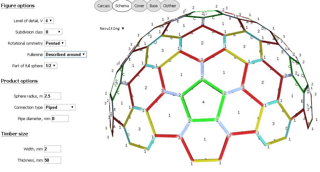
But for now you can use this geodesic dome calculator, very complete and in several languages.
.
If you use these parameters you can get your hexa dome:
- Level of detail (frecuency): 2v
- Subdivision class: I
- Rotational symmetry: Pentad
- Fullerene: Inscribed in
- Part of full spher: 1/2
- Sphere radius: your choise
- Connection type: Piped
- Pipe diameter: 0
Now you should look at the hexagons and where they are located. This 2V dome has two hexagons, one regular and one irregular, such as your dome.
A 4V class II dome has six different hexagons and all are irregular. Check it in the calculator. If you use fullerene: described around, you get three hexes all
irregular ones too.
See two images of 4V calse II.
Regards
Franopio
fran...@gmail.com
This is the calculator mentioned:

thedomeguy
You received this message because you are subscribed to the "Geodesic Help" Google Group
--
--
To post to this group, send email to geodes...@googlegroups.com
--
For more options, visit http://groups.google.com/group/geodesichelp?hl=en
---
You received this message because you are subscribed to the Google Groups "Geodesic Help Group" group.
Gerry in Quebec
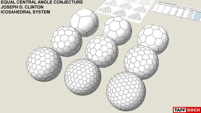
A few ideas on the geometry of the 4v icosa class II geodesic sphere, the starting point of Robert's dome....
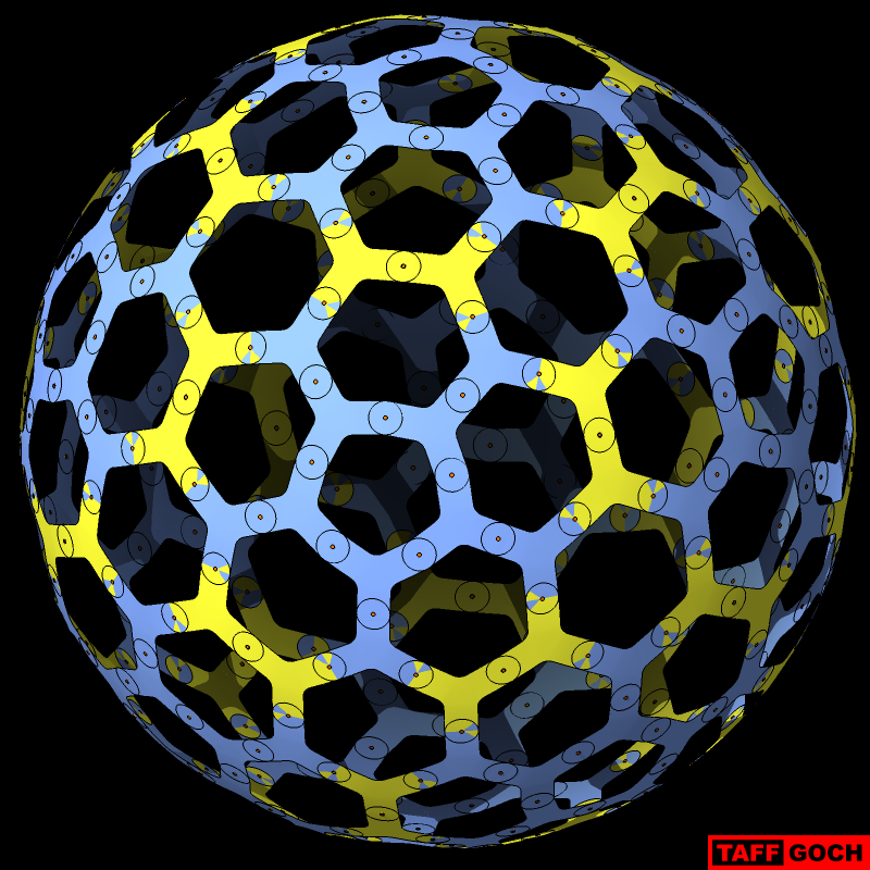
If you generate its geometric dual, you end up with something that looks very much like the full-sphere version of his dome. The dual is a true polyhedron, so all the pent and hex faces are flat. But, unlike the original class II geodesic sphere, not all vertices are the same distance from the spherical centre.
Examples of the class II geodesic sphere and its dual, generated by Antiprism, are attached (images A & B). In the terminology used by Joseph Clinton in his paper about Goldberg spheres with equal central angles, the dual of a 4v icosa class II geodesic sphere would be an I{2,2}, where "I" stands for icosahedron, as opposed to octahedron or tetrahedron. If you were to then triangulate the dual -- making six triangles per hex and five per pent -- it would end up looking like a 6v icosa class I geodesic sphere (image C).
There are all kinds of breakdown methods for geodesic spheres, of course. In the case of the 4v icosa class II, nine of them have only 4 chord factors. (The one Bucky Fuller started out with in the 1940s, if I'm not mistaken, had 5 chord factors.) One of the 4-chord layouts, image C, has a very interesting property: its dual sits flat at the equator when you slice symmetrically through the equatorial hexagons. (None of the others does this.) So, it's an attractive candidate for a physical building, similar to the Eden domes, but with a lower frequency and a higher profile.
Apologies to anyone who's already seen this stuff in a thread a few years ago.
- Gerry in Québec
On Wednesday, December 6, 2017 at 11:16:18 AM UTC-5, Robert Clark wrote:
Well, now I'm confused! When I created the dome, it was definitely a 4V class-II geodesic dome made of triangular panels. I modified the panels by cutting off the corners of each triangle creating a "Y" shape. I assumed it was still a 4V class-II, but with slightly modified panels. Now I found TaffGoch's SketchUp diagram for Goldberg polyhedron and it would appear that my dome is now a 2V class-I Goldberg polyhedron.I'm curious, at what point, as I nibble away the corners of the triangles, does the dome cross a line and go from a 4V class-II to a 2V class-I?Does anyone have an idea about this or any thoughts? I really am suddenly baffled.best regards,Robert
Regards
Ashok
Regards
Ashok
To unsubscribe from this group, send email to GeodesicHelp...@googlegroups.com
--
To post to this group, send email to geodes...@googlegroups.com
--
For more options, visit http://groups.google.com/group/geodesichelp?hl=en
---
You received this message because you are subscribed to the Google Groups "Geodesic Help Group" group.
To unsubscribe from this group and stop receiving emails from it, send an email to geodesichelp...@googlegroups.com.

Adrian Rossiter
On Wed, 6 Dec 2017, Robert Clark wrote:
> it was still a 4V class-II, but with slightly modified panels. Now I found
> TaffGoch's SketchUp diagram for Goldberg polyhedron and it would appear
> that my dome is now a 2V class-I Goldberg polyhedron.
Class II
https://en.wikipedia.org/wiki/Goldberg_polyhedron#Examples
But, the row it appears in on Taff's diagram is row 4 (there
is no model placed on row one), and you can see that on that
row the minimum number of steps (over edges) to travel from one
pentagon to another is 4.
Adrian.
--
Adrian Rossiter
adr...@antiprism.com
http://antiprism.com/adrian
Adrian Rossiter
On Wed, 6 Dec 2017, fran...@gmail.com wrote:
> Hi all, looking the pictures I think this dome is not 4V class II, It is 2V
> Class I, whit fullerene "inscribed In". See my picture atached.
is normally associated with the other parameters. I.e. if you choose
4V, Class II, "described around", then you get the pattern of
Robert's dome.
"inscribed in" appears to correspond to: produce the usual model
(the "described around" model) and then apply the Conway notation
'zip' operation to it
https://en.wikipedia.org/wiki/Conway_polyhedron_notation#Operations_on_polyhedra
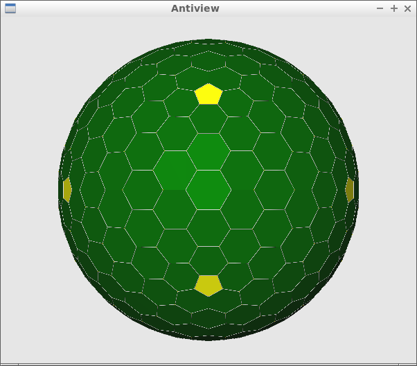
You can make the pattern of Robert's model with the Antiprism command
conway z geo_2_d | antiview
The F4 Class II "inscribed in" model, which would normally be called
a F6 Class I model, is produced with
conway z geo_2_2_d | antiview
[Images attached]
Adrian Rossiter
> "inscribed in" appears to correspond to: produce the usual model
> (the "described around" model) and then apply the Conway notation
> 'zip' operation to it
>
> https://en.wikipedia.org/wiki/Conway_polyhedron_notation#Operations_on_polyhedra
>
> You can make the pattern of Robert's model with the Antiprism command
>
> conway z geo_2_d | antiview
>
> The F4 Class II "inscribed in" model, which would normally be called
> a F6 Class I model, is produced with
>
> conway z geo_2_2_d | antiview
on the Wikipedia page specifically mentions its application to
Goldberg polyhedra, and gives a formula for the transformation.
G(a,b) --z--> G(a+2b,a-b)
G(2,0) --z--> G(2,2) equiv. F4 Class II
G(2,2) --z--> G(2+2*2, 2-2) = G(6,0) equiv. F6 Class I
Francisco
Hi Adrian
The Robert’s dome has three hexagons, one regular and two irregular. See picture 1.
You say “. if you choose 4V, Class II, "described around", then you get the pattern of
Robert's dome”. But this is not correct because 4v, class II, described around has three hexagons too, but all irregular (very irregular). See picture 2.
Look again the Robert`s dome where are the regular hexagons. Now see my third picture attached, you can see the same pattern of the Robert`s dome, This is 2V, class I, inscribed in.
I`m not an expert but this is that I can see according to the software from acidome.ru.
Regards
Franopio
--
--
You received this message because you are subscribed to the "Geodesic Help" Google Group
--
To unsubscribe from this group, send email to GeodesicHelp...@googlegroups.com
--
To post to this group, send email to geodes...@googlegroups.com
--
For more options, visit http://groups.google.com/group/geodesichelp?hl=en
---
You received this message because you are subscribed to a topic in the Google Groups "Geodesic Help Group" group.
To unsubscribe from this topic, visit https://groups.google.com/d/topic/geodesichelp/EREz4d7DO_s/unsubscribe.
To unsubscribe from this group and all its topics, send an email to geodesichelp...@googlegroups.com.
Adrian Rossiter
On Thu, 7 Dec 2017, Francisco wrote:
> The Robert’s dome has three hexagons, one regular and two irregular. See
> picture 1. You say “. if you choose 4V, Class II, "described around",
> then you get the pattern of Robert's dome”. But this is not correct
> because 4v, class II, described around has three hexagons too, but all
> irregular (very irregular). See picture 2.
>
> Look again the Robert`s dome where are the regular hexagons. Now see my
> third picture attached, you can see the same pattern of the Robert`s
> dome, This is 2V, class I, inscribed in.
>
> I`m not an expert but this is that I can see according to the software
> from acidome.ru.
model, what polygons are connected to what polygons - but not the
coordinates of the vertices. Gerry mentioned breakdown methods, which
are used to assign coordinates, and these control geometric properties
like which hexagons are regular.