FIGnition Schematics

Andrew Ebling

Julian Skidmore
I thought I'd give others a chance to answer, and so I'll chip in with my own answer for now!
FIGnition doesn't yet have a schematic! The PCB was designed using a Mac PCB designer called Osmond X which doesn't support schematics (at least in the version I have). The major reason is that I really want a Mac-compatible Schematic editor which is intuitively easy to use and in theory that means one that's pretty much as easy to use as a vector drawing program (though of course it would have to maintain netlists etc).
GitHub contains a veroboard circuit design (done in Stripes) though:
https://github.com/Snial/FIGnition
Stripes is here:
https://sites.google.com/site/libby8dev/stripes
Because of your email I had a go at designing a schematic in Fritzing, but it's not finished yet.
-cheers from julz
The DIY 8-bit computer from nichemachines™
Andrew Ebling
Julian Skidmore
I do plan to. I've found Fritzing a bit buggy (well, it does say Fritzing Alpha). It's schematic editor doesn't seem to produce nice square connections and it's left some netlist connections where I deleted real ones.
I'll try and produce one in the coming week though along with a revision of the Veroboard, Stripes version which works on one board. Do check out Stripes!
https://sites.google.com/site/libby8dev/stripes
-cheers from julz
Julian Skidmore
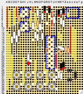
Today I'm doing some work on circuits themselves. Here's the first part, FIGnition on a single stripboard: FIGnition Flint. It's important to me that FIGnition can be built at a pure hobby level and I'll be having a go at building this version this afternoon. I've largely checked the board, but I'll have probably made a mistake or two in the construction.
FIGnition Flint requires a 30x36 hole stripboard, (76.2mm x 92mm) stripboard, roughly half of a 63x38 stripboard and thus takes up 50% more space than a standard FIGnition.
Components aren't annotated in this version, I'll update the diagram in the near future. IC sockets are upside-down, because Stripes doesn't yet support rotating components. The Resistor list (left to right, top to bottom, based on the first hole used) however is:
R8: 1K5 at N2.
R4: 1K at P3
R1: 1K at U4
R2: 68R at X4
R9: 1K at O5
R3: 68R at Y5
R14: 1K5 at L7
R12: 1K5 at E8
R13: 1K at F8
R10: 1K5 at C9
R11: 1K at D9
R17: 1K5 at P9
R16: 220R at N10
R15: 1K at M11.
R7: 220R at J21.
R6: 470R at W28
R5: 1K at X29
Diodes:
D6: N4148 at Q1
D7: N4148 at S1
D3: 3v6 Zener at W2
D4: 3v6 Zener at Y2.
D2: N4148 at Y23.
D1: N4148 at X25.
Caps:
C1: 4u7 at X2
C6: 10n at F5
C5: 10n at N7.
C3: 22p at Z18.
C4: 22p at a19.
C2: 10n at W20
Theoretically, all you need to build FIGnition Flint is the veroboard, a set of components (all of which you can buy from Rapid or Maplin) some jump wire and a programmed AtMega168. Theoretically, you can program an AtMega168 using another FIGnition (though the facility isn't ready yet) or with an Arduino.
The phono socket is represented by a header, and although I don't think anything else needs much of an explanation, I'll issue a revision later.
-cheers from julz
Julian Skidmore
I've finished building a FIGnition Flint, image is attached. It's basically the same as the previous diagram, but as expected, I'd made a few mistakes with the design so you can see some subtle changes. I have yet to test it; I'll do that after I've had this nice drink of tea!
-cheers from julz @P
Andrew Ebling
Julian Skidmore
Thanks for the comments.
Reducing Components
**************************
I certainly agree that a simpler design is better, for the reasons you cite. Let's imagine how that would be done:
The most obvious place to reduce the component count is in the voltage conversion between the AVR and the memory chips. However, the reason they are there is because the AVR must run at 5v and the memory chips must run at 3.6v or below. And the AVR must run at 5v, because if I lower it to 3v6 then the clock frequency must be below 15MHz so then I can either have graphics characters and a lower resolution or non-graphics and decent resolution. So, in a sense the resistors are there for decent video support.
I can't remove components from the USB side, the circuit is taken from the V-USB website and it's fairly minimal.
I could remove 2 diodes from the video generator, but I keep them in for protection.
So, when I look at it; I feel I'm fairly constrained in what I do there. Another alternative is to eliminate SRAM and Flash; use an ATMega328 and run code from its internal Flash (they'd be 16Kb spare) and its SRAM (there'd be 1Kb free). There would be a significant performance boost (no Serial RAM to read); a reduced component count and board size (lower costs), but the computer would be limited by a lack of RAM and storage. But of course someone could say that that's not a problem since we'd just use a desktop computer for storage; or use an external SD card; or just make do with downloading code. But here we'd be getting away from the idea of FIGnition as a self-contained computer; since offline storage is now missing; RAM is much smaller and fixed (you can't run my version of life for example; well, you might, but you'd have to compress the data) etc. It's not so... real, so-to-speak.
So, it's not like I haven't thought about these kinds of things, but I don't yet know of a better solution. Perhaps you can think of one!
Veroboard.
************
Yes, I think veroboard, though error-prone; low-density and quite hacky is really very good for one-off circuit builds. All my designs are first done on a combination of a basic MCU+ bread-board, then prototyped on veroboard; then I'll produce PCBs. I do it that way, because it's a low-barrier to entry, I don't have to pay £50+ for prototype boards with a relatively large turn-around; instead I can design; then build something and correct it in a day or so (I spent 1.5 days on FIGnition Flint).
Since FIGnition is about reducing the barrier to entry, it makes sense to build a Veroboard version. In practice, building a Veroboard version takes much longer and would cost more than buying one from me, because I buy the components in larger quantities; but it enhances the freedom of the project: someone could repurpose the AVR from an Arduino and build their own FIGnition that way.
Second to asking about the keyboard, people ask about expansion ports for FIGnition. That's tricky when there's only really 4 pins free. There is space on the board to use them though. Pin 2 can be mapped to a jumper connection near the phono. Pins 13 and 12 can be mapped to just above and to the right of the Crystal; pin 28 is connected all the way along to pin 27. This means you could stack an expansion board that's 12-pins deep over those areas, the existing pinouts would anchor it on 3 corners already (imagine it going across the Veroboard, on top of the AVR).
FIGnition Flint
****************
Anyway, FIGnition Flint now works, please check out its page on the FIGnition google site and its own discussion:
https://groups.google.com/group/fignition/t/cfd10f2112048066?hl=en
-cheers from julz
Andrew Ebling

Simon

Brian Fairchild
C4, 100n, across the crystal isn't right. The chip wouldn't work.
I suspect, and indeed it ought to be, another small value to ground.
And as a general note, 10pF is a bit too small, I'd normally expect to see 18-22pF around a chips xtal oscillator.
Brian
Brian Fairchild
minium limited
www.minium.co.uk
phone +44 (0) 1353 749101
fax +44 (0) 1353 749099
Andrew Ebling

Brian Marstella
I'm anxiously awaiting my kit; as soon as it arrives, I'll try to
double-check your schematic as I build the unit and provide any
feedback that I can. I'm working on the assumption that there is no
real difference between the NTSC and PAL versions, however. Perhaps
Julian can confirm that just in case there is something differing
between the two.
Regards,
Brian.
On Nov 28, 6:44 am, Andrew Ebling <andrew.ebl...@gmail.com> wrote:
> I need to go back and check all component values - I was probably
> distracted by a "daddy, daddy, daddy..." moment ;-)
>
> On Mon, Nov 28, 2011 at 11:40 AM, Julian Skidmore <
>
>
>
>
>
>
>
> theoriginalsn...@gmail.com> wrote:
> > Hi Brian,
>
> > Indeed, c3 and c4 are both 22pFs. c1 is 4u7, c2; c5 and c6 and 10n.
>
> > -cheers from julz
>
> > On Mon, Nov 28, 2011 at 11:19 AM, Brian Fairchild <gro...@minium.co.uk>wrote:
>
> >> C4, 100n, across the crystal isn't right. The chip wouldn't work.****
>
> >> ** **
>
> >> I suspect, and indeed it ought to be, another small value to ground.****
>
> >> ** **
>
> >> And as a general note, 10pF is a bit too small, I'd normally expect to
> >> see 18-22pF around a chips xtal oscillator.****
>
> >> ** **
>
> >> Brian ****
>
> >> ** **
>
> >> ** **
>
> >> Brian Fairchild
> >> minium limited
> >>www.minium.co.uk
> >> phone +44 (0) 1353 749101
> >> fax +44 (0) 1353 749099****
>
> >> ** **
>
> >> ** **
>
> >> ** **
>
> >> *From:* fign...@googlegroups.com [mailto:fign...@googlegroups.com] *On
> >> Behalf Of *Andrew Ebling
> >> *Sent:* 26 November 2011 20:32
> >> *To:* fign...@googlegroups.com
> >> *Subject:* Re: FIGnition Schematics****
>
> >> ** **
>
> >> Hi everyone,****
>
> >> ** **
>
> >> Still not quite there, but I wanted to share the work I'd started on
> >> schematics of FIGnition. These have been produced in Fritzing using a
> >> combination of the testing netlist and the PCB.****
>
> >> ** **
>
> >> Comments, feedback etc. welcome!****
>
> >> ** **
>
> >> best regards,****
>
> >> ** **
>
> >> Andrew****
>
> > --
Julian Skidmore
There are only some minor timing differences between the two standards.
#ifdef __VideoGenPAL__
#if F_CPU == 12000000
#define kHSyncScan (96-1)
#define kHSyncPulse4us (7-1)
#define kHSyncScanShort (48-1)
#define kHSyncPulse2us (4-1)
//#define kFrameVideoMarginLeft (18-1)
// Working version.
#define kFrameVideoMarginLeft (9-1)
// Add to see bit data go high.
//#define kFrameVideoMarginLeft (19-1)
#define kVideoBuffWidth 30
//#define kVideoBuffWidth 40
#define kVideoBuffHeight 24
#define kUdgChrs 1
#define kVideoDotClock 0
#endif
#ifdef __VideoGenNTSC__
// only 20MHz supported.
#if F_CPU == 20000000
#define kHSyncScan (159-1)
#define kHSyncPulse4us (12-1)
#define kHSyncScanShort (80-1)
#define kHSyncPulse2us (6-1)
#define kFrameVideoMarginLeft (18-1) // actually about 4c later or .2us or 2 pixels.
#define kVideoBuffWidth 25
#define kVideoBuffHeight 24
//#define kVideoBuffWidth 48
#define kUdgChrs 16
#define kVideoDotClock 1
#endif
The frame is built up as follows:
#ifdef __VideoGenPAL__
/**
* A single PAL frame is 312 lines ( int(625/2)).
* 16/2 = 8 lines are used for VSync, leaving 304 for the full frame.
* 192 scans are used for the image leaving 304-192 = 56 for top and bottom
* margin.
**/
#define kFrameSyncPreEqual ((kHSyncScanShort+1)*6)
#define kFrameSyncEqual ((kHSyncScanShort+1)*5)
#define kFrameSyncPostEqual ((kHSyncScanShort+1)*5)
#define kFrameFieldScans 304
#define kFrameVideoScans 192
#define kFrameKeyPromptScans 16
#define kFrameKeyPromptScanPeriod ((kHSyncScan+1)*kFrameKeyPromptScans)
...
#define kFrameKeyPromptLeftmargin (((kVideoBuffWidth-5)/2)*4)
#define kFrameVideoScanperiod ((kHSyncScan+1)*kFrameVideoScans)
#define kFrameVideoMarginTopScans ((kFrameFieldScans-kFrameVideoScans-kFrameKeyPromptScans)/2)
#define kFrameVideoMarginTopScansPeriod (kFrameVideoMarginTopScans*(kHSyncScan+1))
#define kFrameVideoMarginBottomScans (kFrameFieldScans-kFrameVideoScans-kFrameVideoMarginTopScans)
#define kFrameVideoMarginBottomScansPeriod (kFrameVideoMarginBottomScans*(kHSyncScan+1))
#ifdef __VideoGenNTSC__
/**
* A single NTSC frame is 262 lines ( int(525/2)).
* 14/2 = 7 lines are used for VSync, leaving 255 for the full frame.
* 192 scans are used for the image leaving 255-192 = 31 for top margin
* and 255-topMargin-192 for the bottom margin.
**/
#define kFrameSyncPreEqual ((kHSyncScanShort+1)*5)
#define kFrameSyncEqual ((kHSyncScanShort+1)*5)
#define kFrameSyncPostEqual ((kHSyncScanShort+1)*4)
#define kFrameFieldScans 255
#define kFrameVideoScans 192
#define kFrameKeyPromptScans 16
#define kFrameKeyPromptScanPeriod ((kHSyncScan+1)*kFrameKeyPromptScans)
#define kFrameKeyPromptLeftmargin (((kVideoBuffWidth-5)/2)*4)
#define kFrameVideoScanperiod ((kHSyncScan+1)*kFrameVideoScans)
#define kFrameVideoMarginTopScans ((kFrameFieldScans-kFrameVideoScans-kFrameKeyPromptScans)/2)
#define kFrameVideoMarginTopScansPeriod (kFrameVideoMarginTopScans*(kHSyncScan+1))
#define kFrameVideoMarginBottomScans (kFrameFieldScans-kFrameVideoScans-kFrameVideoMarginTopScans)
#define kFrameVideoMarginBottomScansPeriod (kFrameVideoMarginBottomScans*(kHSyncScan+1))
#endif
The sync generation is a pretty simple state machine which is only called once for every new frame region and once for every scan line that contains video data. The sync pulse is generated automatically by Timer0. This improves performance over a number of AVR PAL video designs which require an interrupt for all scan lines. Here's the enum for the states:
/**
* FrameSync is a state machine with a number of states:
* State Action
* ***** ******
* kFrameSyncPreEqualize Sets up HSync to generate short half-scan pulses.
* OCR2A = kHSyncScanShort
* OCR2B = kHSyncPulse2us
* Sets up FrameSync to interrupt in 6 short pulses.
* OCR1A += kFrameSyncPreEqual
* kFrameSyncEqualize Sets up HSync to generate 5 broad half-scan pulses.
* OCR2A = As before.
* OCR2B = (kHSyncScanShort+1)-(kHSyncPulse2us+1)
* -1;
* OCR1A += kFrameSyncEqual
* kFrameSyncPostEqual Sets up HSync to generate 5 short half-scan pulses
* OCR2B = kHSyncPulse2us
* OCR1A += kFrameSyncEqual
* The problem here is that we need to generate a
* FrameSync interrupt after the pulse ends and before
* the next pulse should end and that's only 4us or
* 64cycles. So, we disable all interrupts apart from
* ours at that point!
* OCR1A += kFrameSyncPostEqual
* kFrameSyncTopMargin Sets up HSync to generate a full pulses:
* OCR2A = kHSyncScan;
* OCR2B = kHSyncPulse4us;
* We've done 8 scan lines (shouldn't it be 7.5 or 8.5
* ?). So there's 304 left. We use 192 for real
* video.
* OCR1A += kFrameVideoMarginTopScansPeriod
* kFrameSyncBMVideoPrefetch Sets up HSync to generate full pulses - which is what
* it was doing before. Sets up FrameSync to generate
* ScanLine events.
* kFrameSyncScanStart If scan<maxScanLine then ...
* Disables interrupts apart from FrameSync.
* Sets up a FrameSync interrupt in minWaitCycles and
* sleeps CPU. We generate ScanLine events at the point
* we need = 4us+8us+2us from the beginning of HSync.
* Else
* Sets up FrameSync to interrupt in
* OCR1A += kFrameVideoMarginBottomScansPeriod
* And the next state to kFrameSyncPreEqualize.
* kFrameSyncScanGen rjmp to ScanLine gen (in assembler). Disabled at
* first? ScanGen either ends by setting the state back
* to kFrameSyncScanStart (with the right setting) or
* kFrameSyncPreEqualize after setting the right
* margin.
*
*
* The best place to set FrameSync interrupts is just as the sync completes.
* The best means of handling the state machine is to use a single byte for
* the major state and a separate byte for the scan lines, because we'd need
* 192*2 states to handle scan lines if we were to combine them, so we'd
* need an extra byte anyway. We can't call any subroutines in the ISR
* otherwise the compiler will push a whole pile of registers!
*
* So, the standard FrameSync interrupt will be 4us into a normal frame, just
* as the normal sync pulse would complete.
*
*
* In the Assembler Video scan we use gChrSet to point to the base address of
* the character set + the ScanRow.
* (&kChrSet>>7)+row.
* The gVPtr points to the video base, every 8 scan rows we increment to the
* next gVPtr row.
**/
typedef enum {
kFrameSyncPreEqualize=0,
kFrameSyncEqualize,
kFrameSyncLastEqualize,
kFrameSyncPostEqualize,
kFrameSyncTopMargin,
kFrameSyncBMVideoPrefetch,
kFrameSyncScanLine,
kFrameSyncScanGen,
kFrameSyncBotMargin,
kFrameSyncStatesCount
} tFrameSyncStates;
extern byte gFrameSyncState;
Andrew's usb capture card in NTSC mode seems to display OK, but slightly shifted to the right. That's quite a simple fix (reducing the left margin by 1 will move the image 2 pixels to the left). Actually, you can see the error - on my actual code it says it's (9-1) and in NTSC mode it's set to (18-1) which is similar to my test mode code. Your FIGnition actually does contain the experimental NTSC ROM so you should see it working with an image shifted accordingly.
I'll send you your tracking code in a minute so you can see where your FIGnition is.
-cheers from julz
Brian Marstella
Thanks for the quick response. Since it's only firmware differences,
I'll try to fully document any changes to Andrew's schematic. I don't
currently have the Fritizing program installed but will do so as time
permits. I'm currently switching laptops so everything is in disarray
at the moment. I'll also check alignment as much as possible and
provide some photos and/or descriptive feedback on the firmware fixes.
Regards,
Brian.
On Dec 2, 10:36 am, Julian Skidmore <theoriginalsn...@gmail.com>
> ...
>
> read more »
>
> NmLogoMini.jpg
> 4KViewDownload
>
> FIG - black on whiteMini.jpg
> 13KViewDownload
Andrew Ebling
Thanks for the update. I've realised there are several component values which need correcting - but I now recall why the correct 22pF values weren't assigned to the smooth capacitors; Fritzing would not let me assign this value to a ceramic capacitor. I tried creating a new capacitor type and/or entering the value manually, but I can set the correct value _and_ have Fritzing display the value on the schematic. I tried poking around within the component library to see what I could change, but no cigar. I then tried checking out the source code for the project, but it looks like it is quite an undertaking to get it building.
So if anyone knows how to set custom component values in Fritzing and have the custom values displayed in the schematic, I'd very much like to know how it's done. Then I'll get on and update the FIGnition schematic :).
best regards,
Andrew
Brian Marstella
I'll probably try Fritzing sometime after I get the FIGnition built.
I'll work from the schematic you previously posted and if I can figure
out how it works, I'll let you know.
Regards,
Brian
Brian Marstella
Spent about 2 hours last night assembling the FIGnition. Works great!
I quit about 2:30 am so didn't get a lot of testing done, but did get
some photos of the screen. I'll post them later but the NTSC firmware
looks good so far. I think I'll start a separate thread for that,
though.
Andrew, the schematics seemed to be correct but my eyes were starting
to cross. I didn't check all of the component values since you're
already aware of them and Julz has pretty good documentation on the
web site for the component reference numbers and values.
Thanks to you for getting the schematics together. It makes it much
easier to see what's going on as I've never been very good at
following traces, especially on a densely populated board.
Brian.