IMAX B6 clone with an unknown motherboard and microcontroller
16,322 views
Skip to first unread message

sasam
Jan 22, 2014, 9:26:39 PM1/22/14
to cheali-...@googlegroups.com
Hi everybody,
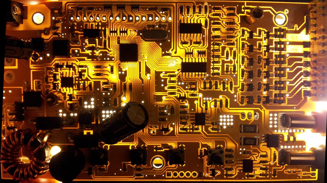
A few days ago, I received an ImaxB6 clone (ordered it from e-bay). I am planning to install cheali-charger firmware on it but the motherboard is different from the photos I can find related to IMAX B6 original and clone. The problem is also that the label on the micro-controller is deleted (sanded) so I do not know what the micro-controller is in the charger. According to number of pins it is not ATMega32.
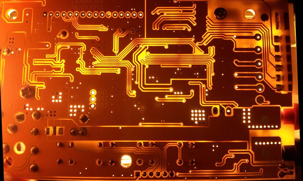
Attached is a few pictures so maybe someone can help.
Does anyone recognize this micro-controller ?
Can it be programmed ?
USBASP programer ?
where is pin for ASP on this board ?
Is it possible to load "Che-charger" firmware?
If not is it possible to modify sw to support this B6 clone?
Thanks,
Sasha
A few days ago, I received an ImaxB6 clone (ordered it from e-bay). I am planning to install cheali-charger firmware on it but the motherboard is different from the photos I can find related to IMAX B6 original and clone. The problem is also that the label on the micro-controller is deleted (sanded) so I do not know what the micro-controller is in the charger. According to number of pins it is not ATMega32.
Attached is a few pictures so maybe someone can help.
Does anyone recognize this micro-controller ?
Can it be programmed ?
USBASP programer ?
where is pin for ASP on this board ?
Is it possible to load "Che-charger" firmware?
If not is it possible to modify sw to support this B6 clone?
Thanks,
Sasha

Paweł Si
Jan 24, 2014, 11:48:53 AM1/24/14
to cheali-...@googlegroups.com
2014/1/23 sasam <sasa.mi...@gmail.com>
Hi everybody,
A few days ago, I received an ImaxB6 clone (ordered it from e-bay). I am planning to install cheali-charger firmware on it but the motherboard is different from the photos I can find related to IMAX B6 original and clone. The problem is also that the label on the micro-controller is deleted (sanded) so I do not know what the micro-controller is in the charger. According to number of pins it is not ATMega32.
Attached is a few pictures so maybe someone can help.
This is the first time I see such a charger,
I have no idea what kind of processor this is,
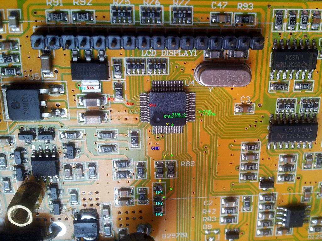
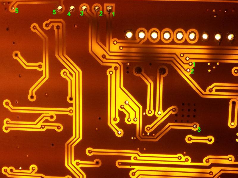
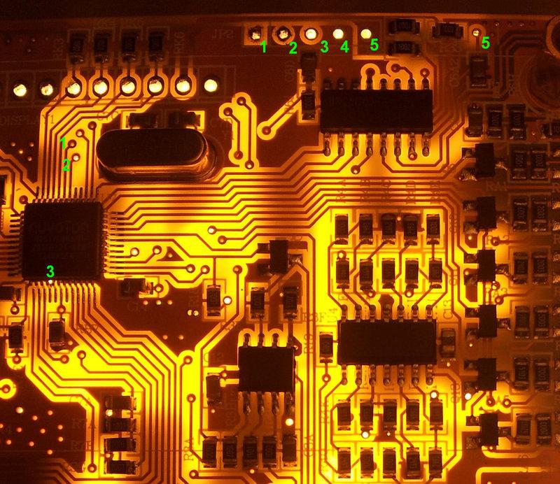
but You could check which pins are connected to:
1. Vcc
2. GND
3. the crystal oscillator
Does anyone recognize this micro-controller ?
Can it be programmed ?
USBASP programer ?
where is pin for ASP on this board ?
Is it possible to load "Che-charger" firmware?
definitely not! the pin layout is different.
If not is it possible to modify sw to support this B6 clone?
It might be possible, depends on the CPU.

Hans Schmitd
Jan 29, 2014, 4:48:26 PM1/29/14
to cheali-...@googlegroups.com
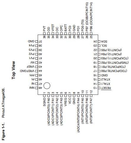
If it is AVR at all, the only possibilities with 48 pins would be Atmega406, AT32UC3B164, AT32UC3B1128, AT32UC3B1256, AT32UC3B1512, AT32UC3L016, AT32UC3L032, or AT32UC3L064.
Otherwise it might be STM8 or something - maybe more likely.
The 6 pins at the bottom might be ISP or JTAG. You could try asking the CPU what its ID is, to find out what chip it is.
Otherwise it might be STM8 or something - maybe more likely.
The 6 pins at the bottom might be ISP or JTAG. You could try asking the CPU what its ID is, to find out what chip it is.
sasam
Feb 4, 2014, 8:53:21 AM2/4/14
to cheali-...@googlegroups.com
Dana petak, 24. siječnja 2014. 17:48:53 UTC+1, korisnik cheali-charger napisao je:
2014/1/23 sasam <sasa.mi...@gmail.com>
Hi everybody,
A few days ago, I received an ImaxB6 clone (ordered it from e-bay). I am planning to install cheali-charger firmware on it but the motherboard is different from the photos I can find related to IMAX B6 original and clone. The problem is also that the label on the micro-controller is deleted (sanded) so I do not know what the micro-controller is in the charger. According to number of pins it is not ATMega32.
Attached is a few pictures so maybe someone can help.
This is the first time I see such a charger,I have no idea what kind of processor this is,but You could check which pins are connected to:1. Vcc2. GND3. the crystal oscillatorDoes anyone recognize this micro-controller ?
Can it be programmed ?
USBASP programer ?
where is pin for ASP on this board ?
Is it possible to load "Che-charger" firmware?definitely not! the pin layout is different.
I tried to investigate little bit, but unfortunately I am not electronic expert, an probably it is only waste a time for me.
If documentation form link http://www.atmel.com/Images/Atmel-2548-8-bit-AVR-Microcontroller-Battery-Management-ATmega406_Datasheet.pdf
is correct I am pretty sure there is not ATmega406 in this charger. Vcc pin and cristal (Xtal1& Xtal2) pins are on other place. Look at the photos in the attachment.
If not is it possible to modify sw to support this B6 clone?It might be possible, depends on the CPU.
My conclusion is there is no sense for me and I will tray to sell this charger and try to bye new one with ATmega32 / I hope :) /
sasam
Feb 4, 2014, 9:34:09 AM2/4/14
to cheali-...@googlegroups.com
Dana srijeda, 29. siječnja 2014. 22:48:26 UTC+1, korisnik Hans Schmitd napisao je:
If it is AVR at all, the only possibilities with 48 pins would be Atmega406, AT32UC3B164, AT32UC3B1128, AT32UC3B1256, AT32UC3B1512, AT32UC3L016, AT32UC3L032, or AT32UC3L064.
Otherwise it might be STM8 or something - maybe more likely.
The 6 pins at the bottom might be ISP or JTAG. You could try asking the CPU what its ID is, to find out what chip it is.
How to connect ISP or JTAG to this 6 bottom pins?
4 pins from this 6 bottom pins are ended next to MCU pins where TP2 connector pin ended (pins 9-12).
Is it possible to use same pins for button press recognition and CPU programing ?
I think there is possibility that connection pins which are labeled as TP1, TP2, TP3 & TP4 can be used for programing or it is just serial port or I don't know what ....
TP3=GND
TP4=Vcc
TP1=connected directly to MCU (pin 6) over one 100ohm resistor
TP2=connected directly to MCU (pin 8) over one 100ohm resistor
Paweł Si
Feb 4, 2014, 10:27:19 AM2/4/14
to cheali-...@googlegroups.com
I checked all STM8 LQFP-48 microcontrollers,
they also don't fit, all of them use Pin 2,3 for the oscillator.
--
You received this message because you are subscribed to the Google Groups "cheali-charger" group.
To unsubscribe from this group and stop receiving emails from it, send an email to cheali-charge...@googlegroups.com.
For more options, visit https://groups.google.com/groups/opt_out.
sasam
Feb 25, 2014, 6:51:57 PM2/25/14
to cheali-...@googlegroups.com
I really have no luck with Imax B6 clones :(
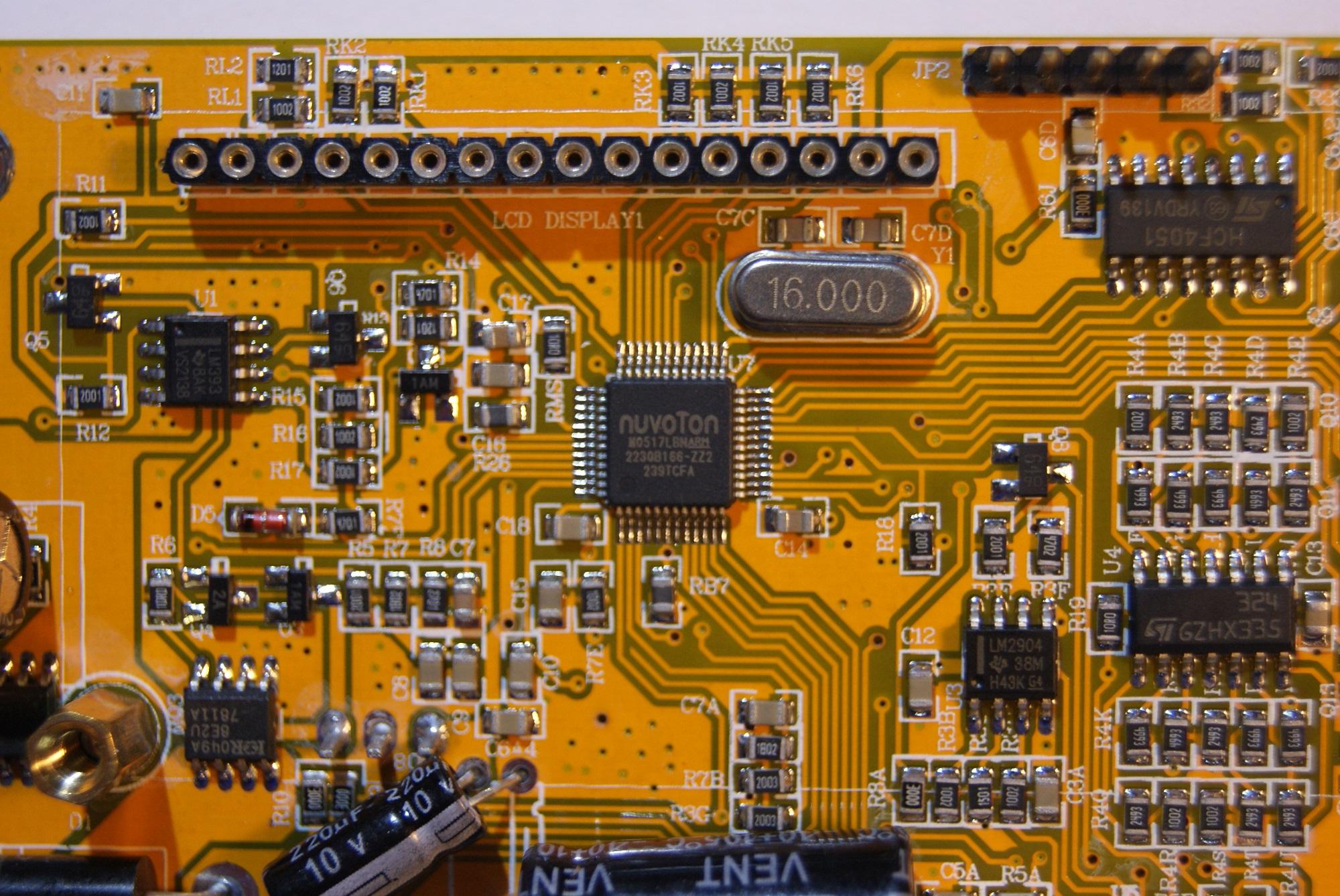
I received a second Imax B6, but it is not with ATmega32. On this charger controller label is not deleted so I finally know controller name. Same controller is on the first charger but PCB layout is different.
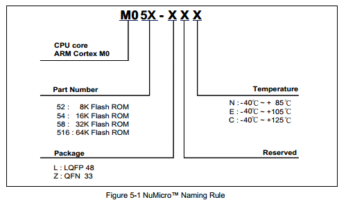
Micro-controllers in both charger are M0517LBN an Chinese version of ARM Cortex M0.
http://www.nuvoton.com/NuvotonMOSS/Community/ProductInfo.aspx?tp_GUID=ca35dc89-c740-421a-b13b-5a8d050315e3
I received a second Imax B6, but it is not with ATmega32. On this charger controller label is not deleted so I finally know controller name. Same controller is on the first charger but PCB layout is different.
Micro-controllers in both charger are M0517LBN an Chinese version of ARM Cortex M0.
http://www.nuvoton.com/NuvotonMOSS/Community/ProductInfo.aspx?tp_GUID=ca35dc89-c740-421a-b13b-5a8d050315e3
sasam
Feb 25, 2014, 7:11:32 PM2/25/14
to cheali-...@googlegroups.com
On this charger NiMh, NiCd and Pb program don't work. They report "connection break" just after charging start. LiPo program seems to work but accuracy is problematic. PCB layout on this charger is similar to original B6 except diferen micro-controller.
Paweł Si
Feb 26, 2014, 6:03:54 AM2/26/14
to cheali-...@googlegroups.com
2014-02-26 0:51 GMT+01:00 sasam <sasa.mi...@gmail.com>:
I really have no luck with Imax B6 clones :(
:(
I received a second Imax B6, but it is not with ATmega32. On this charger controller label is not deleted so I finally know controller name. Same controller is on the first charger but PCB layout is different.
Micro-controllers in both charger are M0517LBN an Chinese version of ARM Cortex M0.
http://www.nuvoton.com/NuvotonMOSS/Community/ProductInfo.aspx?tp_GUID=ca35dc89-c740-421a-b13b-5a8d050315e3
I looked at M0516LBN datasheet (I couldn't find M0517LBN),
and It doesn't look so bad:
1. 64kB program memory (M0517LBN may have even more)
2. 4kB RAM
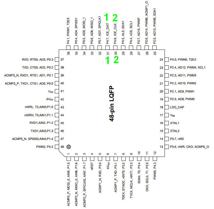
3. Serial wire debug interface - 2 wires ICE_DAT,ICE_CLK (pin 31, 30)
4. 12bit ADC - (atmega32 has only 10bit)
5. 32bit ARM Cortex M0
.
.
If You know how to program in C, and if have some experience in embedded systems,
You could try to add support for this charger,
unfortunately, it will take some time
Best Regards,
Paweł
sasam
Feb 26, 2014, 9:31:20 AM2/26/14
to cheali-...@googlegroups.com
Dana srijeda, 26. veljače 2014. 12:03:54 UTC+1, korisnik cheali-charger napisao je:
2014-02-26 0:51 GMT+01:00 sasam <sasa.mi...@gmail.com>:
I really have no luck with Imax B6 clones :(
:(I received a second Imax B6, but it is not with ATmega32. On this charger controller label is not deleted so I finally know controller name. Same controller is on the first charger but PCB layout is different.
Micro-controllers in both charger are M0517LBN an Chinese version of ARM Cortex M0.
http://www.nuvoton.com/NuvotonMOSS/Community/ProductInfo.aspx?tp_GUID=ca35dc89-c740-421a-b13b-5a8d050315e3
I looked at M0516LBN datasheet (I couldn't find M0517LBN),and It doesn't look so bad:1. 64kB program memory (M0517LBN may have even more)2. 4kB RAM3. Serial wire debug interface - 2 wires ICE_DAT,ICE_CLK (pin 31, 30)4. 12bit ADC - (atmega32 has only 10bit)5. 32bit ARM Cortex M0.
According Chinese forum: http://www.nuvoton-m0.com/english/forum.php?mod=viewthread&tid=32&extra=page%3D1 M0517LBN is the special version of M0516LBN but with inaccurate internal oscillator. I hope it is only difference :)
If You know how to program in C, and if have some experience in embedded systems,You could try to add support for this charger,unfortunately, it will take some timeBest Regards,Paweł
I know how to program in C, and unfortunately I haven't experience with embedded systems. But Why not to tray with this B6 :)
Do You know where I can find compiler/development env. for this micro controller, and what I need to flash new SW to them?
Best Regards,
Saša
Paweł Si
Feb 26, 2014, 5:09:31 PM2/26/14
to cheali-...@googlegroups.com
2014-02-26 15:31 GMT+01:00 sasam <sasa.mi...@gmail.com>:
According Chinese forum: http://www.nuvoton-m0.com/english/forum.php?mod=viewthread&tid=32&extra=page%3D1 M0517LBN is the special version of M0516LBN but with inaccurate internal oscillator. I hope it is only difference :)
I see is a crystal oscillator so it shouldn't be a problem.
I know how to program in C, and unfortunately I haven't experience with embedded systems. But Why not to tray with this B6 :)
Do You know where I can find compiler/development env. for this micro controller, and
You should be aware that I don't know anything about these processors
I did some small programs on a Cortex M4 but I had a starter kit,
so this shouldn't count.
But there is currently a edx course for embedded systems running:
They also teach about ARM Cortex M4, but M0 is just a cheaper version of it.
I used: eclipse, openocd, arm-none-eabi-gcc
but I wouldn't say that's a recommendation ;)
what I need to flash new SW to them?
Your guess is as good as mine :(
You should first test if you are able to monitor the charger with the current firmware in logView,
you will probably need for that a UART->USB dongle - for example: http://www.ebay.com/itm/6Pin-USB-2-0-to-TTL-UART-Module-Serial-Converter-CP2102-STC-Replace-Ft232-Module-/400565980256?pt=LH_DefaultDomain_0&hash=item5d4397cc60
At the first step You will be on your own.
1. You should write a simple program which will allow you to communicate with your PC,
through the UART, a "hello world" program.
2. after that you will have to rewrite these files:
core\memory.h
core\Timer.h
core\Timer.cpp
core\Serial.cpp
core\Serial.h
core\LiquidCrystal.cpp
core\LiquidCrystal.h
hardware\imaxB6-generic\*
(ALL files in hardware\imaxB6-generic)
please look at them to see how much work it is.
3. I will have to remove Atmega32 dependencies from all other files.
The thing is that I will not change anything (3.) until you succeed with 1.
and your enthusiasm doesn't change :)
what do you think?
Best Regards,
Paweł
sasam
Feb 26, 2014, 8:47:02 PM2/26/14
to cheali-...@googlegroups.com
I used: eclipse, openocd, arm-none-eabi-gccbut I wouldn't say that's a recommendation ;)what I need to flash new SW to them?
Your guess is as good as mine :(
You should first test if you are able to monitor the charger with the current firmware in logView,you will probably need for that a UART->USB dongle - for example: http://www.ebay.com/itm/6Pin-USB-2-0-to-TTL-UART-Module-Serial-Converter-CP2102-STC-Replace-Ft232-Module-/400565980256?pt=LH_DefaultDomain_0&hash=item5d4397cc60
On the previous B6 temp sensor work OK but on the last one it doesn't work. In the current FW there is no options to select serial or USB output. Also when I tray to charge NiMh or Pb batery program imidietly report broken connection. I don't know is it HW or SW problem. I will try to investigate what is the problem.
At the first step You will be on your own.1. You should write a simple program which will allow you to communicate with your PC,through the UART, a "hello world" program.2. after that you will have to rewrite these files:core\memory.hcore\Timer.hcore\Timer.cppcore\Serial.cppcore\Serial.hcore\LiquidCrystal.cppcore\LiquidCrystal.hhardware\imaxB6-generic\*(ALL files in hardware\imaxB6-generic)please look at them to see how much work it is.3. I will have to remove Atmega32 dependencies from all other files.The thing is that I will not change anything (3.) until you succeed with 1.
and your enthusiasm doesn't change :)what do you think?Best Regards,Paweł
I agree there is so much work for this, long, long term project for me. Probably i newer succeed with 1 :)
I will start with documentation, then tray to read and write current FW, and then transform this charger to ARM M0 development board.
Best Regards,
Saša
sasam
Feb 27, 2014, 10:00:55 PM2/27/14
to cheali-...@googlegroups.com
You should first test if you are able to monitor the charger with the current firmware in logView,you will probably need for that a UART->USB dongle - for example: http://www.ebay.com/itm/6Pin-USB-2-0-to-TTL-UART-Module-Serial-Converter-CP2102-STC-Replace-Ft232-Module-/400565980256?pt=LH_DefaultDomain_0&hash=item5d4397cc60
On the previous B6 temp sensor work OK but on the last one it doesn't work. In the current FW there is no options to select serial or USB output. Also when I tray to charge NiMh or Pb batery program imidietly report broken connection. I don't know is it HW or SW problem. I will try to investigate what is the problem.
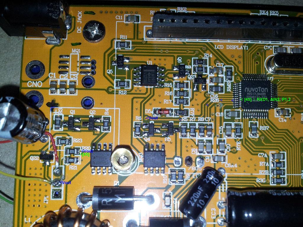
Temp. sensor work now, probably i broke some metalized pad when I unsolderd connector. Now i solder external connector with wires.
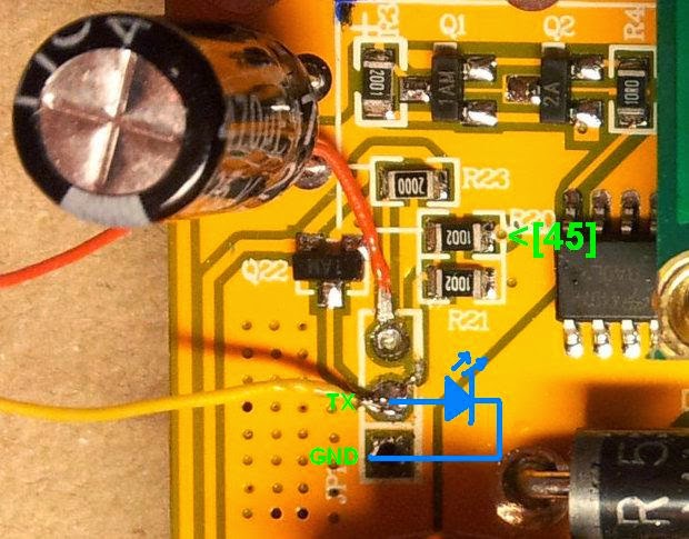
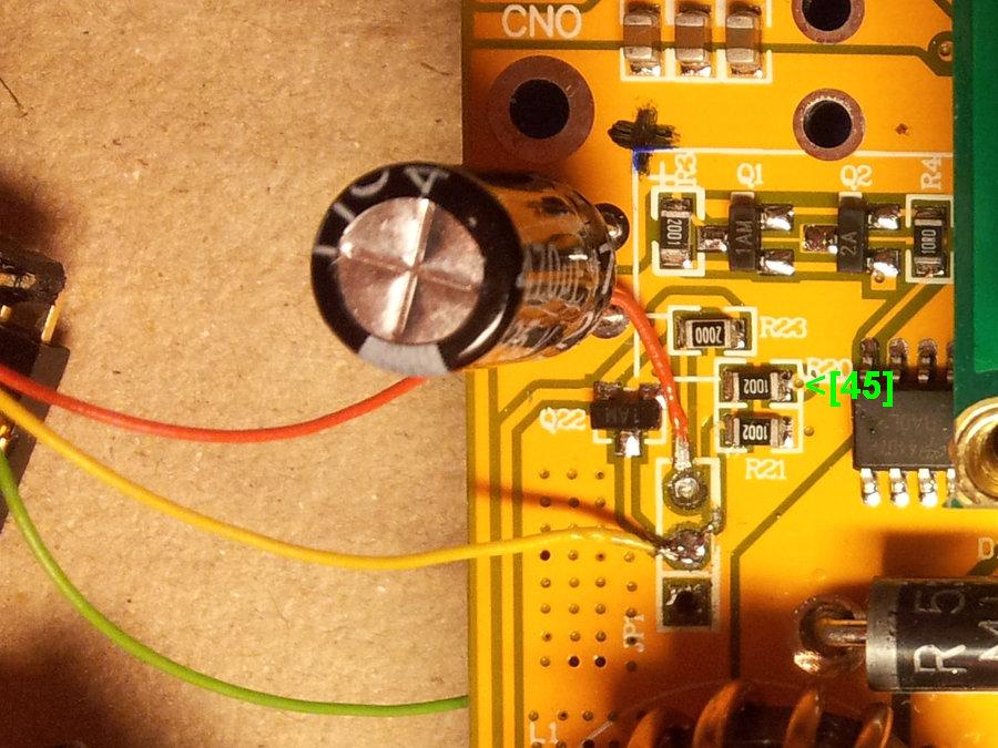
Vout is connected to MPU pin [45]:(RXD1, AIN2, P1.2). So probably with current FW it is not possible to feed LogView over temp sensor :(
Do you suppose the reason why NiMhi, NiCd and Pb program immediately after start terminate with message "connection break"?
Best Regards,
Saša
Paweł Si
Feb 28, 2014, 5:58:53 AM2/28/14
to cheali-...@googlegroups.com
2014-02-28 4:00 GMT+01:00 sasam <sasa.mi...@gmail.com>:
You should first test if you are able to monitor the charger with the current firmware in logView,you will probably need for that a UART->USB dongle - for example: http://www.ebay.com/itm/6Pin-USB-2-0-to-TTL-UART-Module-Serial-Converter-CP2102-STC-Replace-Ft232-Module-/400565980256?pt=LH_DefaultDomain_0&hash=item5d4397cc60
On the previous B6 temp sensor work OK but on the last one it doesn't work. In the current FW there is no options to select serial or USB output. Also when I tray to charge NiMh or Pb batery program imidietly report broken connection. I don't know is it HW or SW problem. I will try to investigate what is the problem.
Temp. sensor work now, probably i broke some metalized pad when I unsolderd connector. Now i solder external connector with wires.
Vout is connected to MPU pin [45]:(RXD1, AIN2, P1.2). So probably with current FW it is not possible to feed LogView over temp sensor :(
In the atmega32 version a TXD pin is also connected to the temp. sensor connector,
so you're probably right.
but maybe it's not such a big problem, You have (probably) a fully functional JTAG output,
so you will be able to debug your code through it.
I looked ad JTAGs dongles provided by Nuvoton:
there is a "Nu-Link" or "Nu-Link-Pro" programmer,
unfortunately it's not very cheap: 35$
Do you suppose the reason why NiMhi, NiCd and Pb program immediately after start terminate with message "connection break"?
I can only speak for cheali-charger, it happens when the battery cables are wrong (not) connected.
Best Regards,
Saša
sasam
Feb 28, 2014, 7:46:23 AM2/28/14
to cheali-...@googlegroups.com
Dana petak, 28. veljače 2014. 11:58:53 UTC+1, korisnik cheali-charger napisao je:
2014-02-28 4:00 GMT+01:00 sasam <sasa.mi...@gmail.com>:
You should first test if you are able to monitor the charger with the current firmware in logView,you will probably need for that a UART->USB dongle - for example: http://www.ebay.com/itm/6Pin-USB-2-0-to-TTL-UART-Module-Serial-Converter-CP2102-STC-Replace-Ft232-Module-/400565980256?pt=LH_DefaultDomain_0&hash=item5d4397cc60
On the previous B6 temp sensor work OK but on the last one it doesn't work. In the current FW there is no options to select serial or USB output. Also when I tray to charge NiMh or Pb batery program imidietly report broken connection. I don't know is it HW or SW problem. I will try to investigate what is the problem.
Temp. sensor work now, probably i broke some metalized pad when I unsolderd connector. Now i solder external connector with wires.
Vout is connected to MPU pin [45]:(RXD1, AIN2, P1.2). So probably with current FW it is not possible to feed LogView over temp sensor :(
In the atmega32 version a TXD pin is also connected to the temp. sensor connector,so you're probably right.but maybe it's not such a big problem, You have (probably) a fully functional JTAG output,so you will be able to debug your code through it.
I think JTAG is OK. layout in JP2 connector according picture which I sent before are:
JP2 Description
1 ICE_DAT
2 ICE_CLK
3 ICE_ RST
4 GND
5 VCC
I looked ad JTAGs dongles provided by Nuvoton:there is a "Nu-Link" or "Nu-Link-Pro" programmer,unfortunately it's not very cheap: 35$
Yes it is expensive :( ( especially when compare with atmega32 flash tool )
I show it here http://www.coocox.org/NuLink.htm
On the bottom of page is shematic for NuLing boar
maybe somebody producing chiper version :)
Do you suppose the reason why NiMhi, NiCd and Pb program immediately after start terminate with message "connection break"?I can only speak for cheali-charger, it happens when the battery cables are wrong (not) connected.
Cables are OK, it work wihout any problems on may old Isl 6-330d.

Paulius Rutkauskas
Feb 28, 2014, 8:50:33 AM2/28/14
to cheali-...@googlegroups.com
Hello all,
there is chipper version of Nu-Link :)
p.s. I got the same new buggy version of imax b6 clone.... :)
Paulius.
sasam
Feb 28, 2014, 10:26:46 AM2/28/14
to cheali-...@googlegroups.com
On Friday, February 28, 2014 2:50:33 PM UTC+1, Paulius Rutkauskas wrote:
Hello all,there is chipper version of Nu-Link :)
Great! but unfortunately shipping to Croatia is not free :(
shipping: US $44.68to Croatia/hrvatska via EMS
- Total Price: US $55.48 :(
Paulius Rutkauskas
Mar 6, 2014, 12:19:18 PM3/6/14
to cheali-...@googlegroups.com
Maybe we could buy and send to you if you will try to make fw for this hardware :-), now it is 12,60 USD and free shipping to Lithuania.
Paulius
sasam
Mar 8, 2014, 8:26:32 PM3/8/14
to cheali-...@googlegroups.com
Thanks for the offer, but I think it is not good idea because I newer play with any micro-controller.
I think it's unlikely that I will be able to do something useful with this charger but we will see :)
Last week I was a little negotiating with the owner of the web shop. He was very kind and this HW sent to me via Chinese-airmail with free shipping :)
Now I have tracking number RC120695052CN .
According to tracking the package is still in China but I hope it will move soon.
sasam
Mar 20, 2014, 8:16:09 AM3/20/14
to cheali-...@googlegroups.com
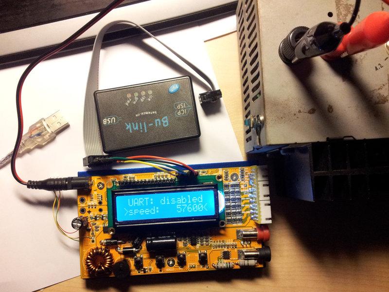
Today my Bu-link arrived :)
Now I must find appropriate driver, and development environment.
Any suggestions for appropriate driver, and development environment are welcome.
Few week ago when I take quick look at Nuvoton flash tools I didn't see option for read and save existing FW, only write new one.
Does somebody know is it possible to read and save existing FW for ARM Cortex M0 ?
Which tool I need for that ?

Paweł Si
Apr 9, 2014, 4:27:40 PM4/9/14
to cheali-...@googlegroups.com
Hi sasam,
How is Your charger doing?
sasam
Apr 9, 2014, 6:20:46 PM4/9/14
to cheali-...@googlegroups.com
Hi Paweł,
I haven't enough time to play more seriously with my charger and Bu-Link (Nu-link). I just instaled CooCox sw, flash last FW on Bu-Link (Nu-link) and I try to read existing FW.. Unfortunately this is not posible with last version of "CooCox CoFlash" SW
On CooCox forum they conform that: http://www.coocox.org/forum/topic.php?id=3622#post-12261
After this attempt I didn't tray to find another SW, but i will try when I catch some time.
Flying sesion is on, for RC & real glider and this is where I spend most of my spare time now.
My idea for first step with this charger is to read existing FW, and flash it back. After that I can play with your charger SW.
Regards,
Saša

dfg gh
May 3, 2014, 4:08:39 PM5/3/14
to cheali-...@googlegroups.com
Hi,
great work you're doing here, Pawel!
Unfortunately, I do seem to have the M0517LBNversion, too.
Now I tried to get some serial output from the 3-pin temperatue connector. No luck.
I'm using the serial connector of an Arduino mega, which works fine with other devices...
I'm not saying that it can't be my bad, but maybe they left that out in the firmware? Btw, what voltages does the temp-sensor produce on the middle pin? I want to see if at least temperature sensing is working...
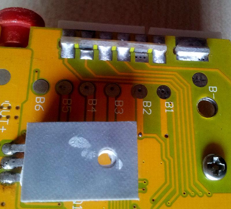
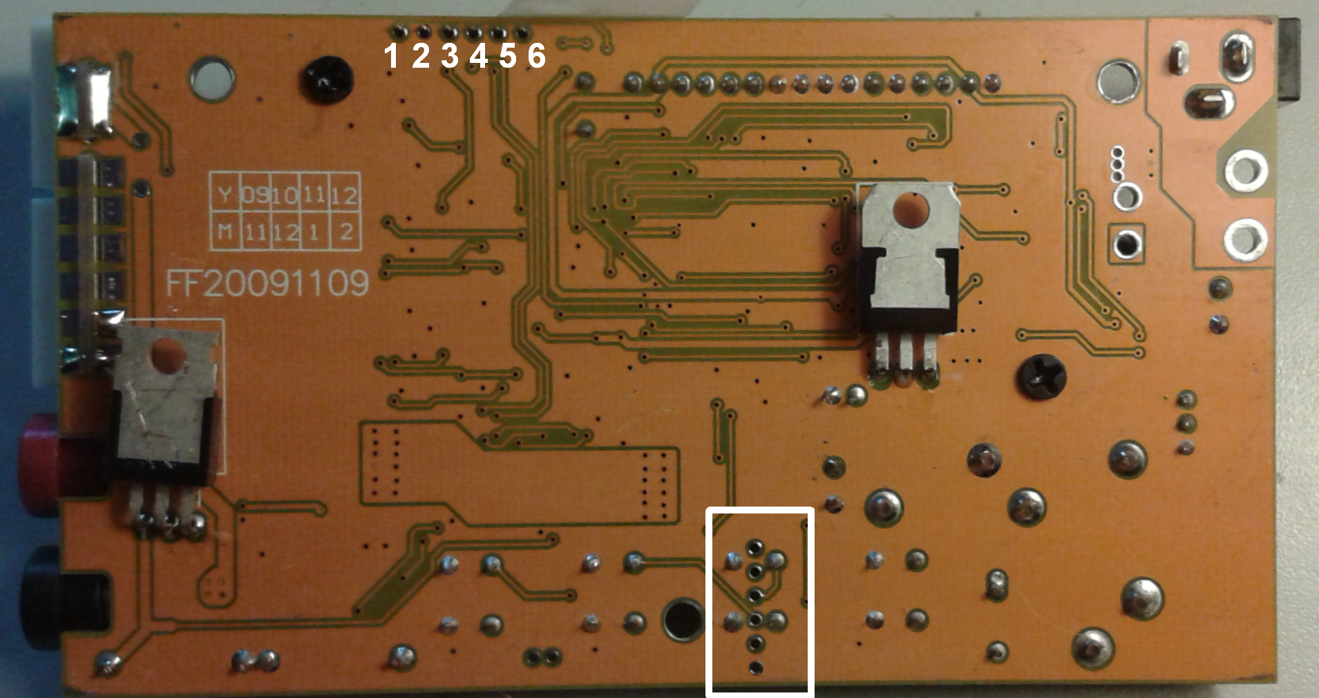
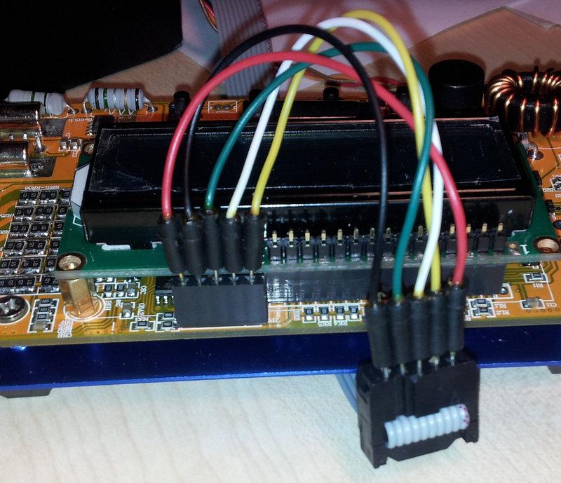
I soldered connectors to the JTAG connector, but my layout is slightly different. I have 6 pins right next to each other (see attachements). I identified Ground and Vcc as pin 5 and 6, but for the rest I need to desolder the display connections which I yet am reluctant to do.
Next problem is the how to use the JTAG. The info I found about JTAG has different pin names (TMS, TDI, TDO, TCK), so I don't know how to connect them.
With said pin names I have found an Arduino sketch to communicate via JTAG which would be a great and easy option versus a proprietary interface imho...
I hope somebody can make more sense of it than me...
Bastian
great work you're doing here, Pawel!
Unfortunately, I do seem to have the M0517LBNversion, too.
Now I tried to get some serial output from the 3-pin temperatue connector. No luck.
I'm using the serial connector of an Arduino mega, which works fine with other devices...
I'm not saying that it can't be my bad, but maybe they left that out in the firmware? Btw, what voltages does the temp-sensor produce on the middle pin? I want to see if at least temperature sensing is working...
I soldered connectors to the JTAG connector, but my layout is slightly different. I have 6 pins right next to each other (see attachements). I identified Ground and Vcc as pin 5 and 6, but for the rest I need to desolder the display connections which I yet am reluctant to do.
Next problem is the how to use the JTAG. The info I found about JTAG has different pin names (TMS, TDI, TDO, TCK), so I don't know how to connect them.
With said pin names I have found an Arduino sketch to communicate via JTAG which would be a great and easy option versus a proprietary interface imho...
I hope somebody can make more sense of it than me...
Bastian
Paweł Si
May 3, 2014, 7:02:55 PM5/3/14
to cheali-...@googlegroups.com
2014-05-03 22:08 GMT+02:00 dfg gh <bbe...@gmail.com>:
Hi,
great work you're doing here, Pawel!
Unfortunately, I do seem to have the M0517LBNversion, too.
Now I tried to get some serial output from the 3-pin temperatue connector. No luck.
I'm using the serial connector of an Arduino mega, which works fine with other devices...
I'm not saying that it can't be my bad, but maybe they left that out in the firmware?
maybe, the charger should have a UART enable/disable option to be able to use the 3 pin connector for both.
Btw, what voltages does the temp-sensor produce on the middle pin? I want to see if at least temperature sensing is working...
I have ~0.7V for room temperature.
I soldered connectors to the JTAG connector, but my layout is slightly different. I have 6 pins right next to each other (see attachements). I identified Ground and Vcc as pin 5 and 6, but for the rest I need to desolder the display connections which I yet am reluctant to do.
Next problem is the how to use the JTAG. The info I found about JTAG has different pin names (TMS, TDI, TDO, TCK), so I don't know how to connect them.
According to:
http://download.nuvoton.com/NuvotonMOSS/DownloadService/Member/DocumentsInfo.aspx?tp_GUID=%20UG0220130918160904
http://download.nuvoton.com/NuvotonMOSS/DownloadService/Member/DocumentsInfo.aspx?tp_GUID=%20UG0220130918160904
You should at least have: VCC, GND, ICE_CLK, ICE_DAT
please see also:
But I must admit that I probably know less than you.
With said pin names I have found an Arduino sketch to communicate via JTAG which would be a great and easy option versus a proprietary interface imho...
I hope somebody can make more sense of it than me...
Bastian
--
You received this message because you are subscribed to the Google Groups "cheali-charger" group.
To unsubscribe from this group and stop receiving emails from it, send an email to cheali-charge...@googlegroups.com.
For more options, visit https://groups.google.com/d/optout.
dfg gh
May 4, 2014, 3:14:02 AM5/4/14
to cheali-...@googlegroups.com
Am Sonntag, 4. Mai 2014 01:02:55 UTC+2 schrieb cheali-charger:
2014-05-03 22:08 GMT+02:00 dfg gh <bbe...@gmail.com>:maybe, the charger should have a UART enable/disable option to be able to use the 3 pin connector for both
It does, but I couldn't get a read at all. Maybe I should try to switch between USB enable and disable while listening...
In the standard layout, I read there is a RX pin connected somewhere to the balancer pins. Where exactly?
Maybe I can talk it into talking to me^^
I have ~0.7V for room temperature.
Good to know, I'll try feeding that in via a voltage divider, see if the temperature sensing works at least...
According to:
You should at least have: VCC, GND, ICE_CLK, ICE_DAT
please see also:
I saw that in the previous posts, but I couldn't find any reference to ICE_CLK, ICE_DAT pins online, so I wouldn't know which equals which pin. Is ICE_DAT bidirectional?
I'll read up in the reference paper you posted :)
But I must admit that I probably know less than you.
Haha, not what I wanted to hear, but a good answer anyway :)
I'll post my results when I have them...
Bastian
Paweł Si
May 4, 2014, 3:28:38 PM5/4/14
to cheali-...@googlegroups.com
2014-05-04 9:14 GMT+02:00 dfg gh <bbe...@gmail.com>:
It does, but I couldn't get a read at all. Maybe I should try to switch between USB enable and disable while listening...
In the standard layout, I read there is a RX pin connected somewhere to the balancer pins. Where exactly?
Maybe I can talk it into talking to me^^
The RX input is not used on the atmega32,
they had not enough pins, so they used the RX pin for balancing.
Good to know, I'll try feeding that in via a voltage divider, see if the temperature sensing works at least...According to:You should at least have: VCC, GND, ICE_CLK, ICE_DATplease see also:
I saw that in the previous posts, but I couldn't find any reference to ICE_CLK, ICE_DAT pins online, so I wouldn't know which equals which pin. Is ICE_DAT bidirectional?
Probably :)
I'll read up in the reference paper you posted :)Haha, not what I wanted to hear, but a good answer anyway :)But I must admit that I probably know less than you.
That's the truth :)
But It's never too late to learn something ;)
Can You tell me which adruino->JTAG you meant?
There is also the problem that currently cheali-charger dosn't support ARM CPUs,
and to write the missing parts the JTAG should support debugging.
Maybe I just buy the charger with the appropriate JTAG.
Can you tell me where you bought yours?
dfg gh
May 4, 2014, 4:52:27 PM5/4/14
to cheali-...@googlegroups.com
Am Sonntag, 4. Mai 2014 21:28:38 UTC+2 schrieb cheali-charger:
The RX input is not used on the atmega32,they had not enough pins, so they used the RX pin for balancing.
Ok. Maybe the 48-pin arm controller's got more pins left...
I saw that in the previous posts, but I couldn't find any reference to ICE_CLK, ICE_DAT pins online, so I wouldn't know which equals which pin. Is ICE_DAT bidirectional?Probably :)I'll read up in the reference paper you posted :)Haha, not what I wanted to hear, but a good answer anyway :)But I must admit that I probably know less than you.That's the truth :)But It's never too late to learn something ;)
Indeed, it isn't..
I started the online course you posted. But I'm still at the numbers part...
Can You tell me which adruino->JTAG you meant?There is also the problem that currently cheali-charger dosn't support ARM CPUs,and to write the missing parts the JTAG should support debugging.Maybe I just buy the charger with the appropriate JTAG.Can you tell me where you bought yours?
Arduino JTAG-Bitbanger:
http://www.khjk.org/log/2013/aug/jtagbang.html
The Arduino Due has both JTAG and SWD...
And it's just about 11€ on Aliexpress...
Maybe I need one :D
I bought my charger from henryhope. Unfortunately, he doesn't seem to sell that model anymore.
I could send you mine if that makes any sense (shipping etc...).
I tested the temperature sensing today...
0V -> 0°C
0.8V -> 80°C
Quite different from yours. Seems a bit strange to me...
Back to serial wire debug... This Article seems to contain a lot of info for bitbanging SWD. Didn't read everything in detail yet.
Is there any resemblance between ARM SWD and AVR Debug Wire? Arduinos would be able to use that...
Now, enough for today :)
Good night,
Bastian
Paweł Si
May 6, 2014, 6:18:14 PM5/6/14
to cheali-...@googlegroups.com
Ok, I bought a new charger, I hope it's the ARM one,
thanks Saša
thanks Saša
Also some interesting sites:
2014-05-05 20:59 GMT+02:00 Sasa Mihajlovic <sasa.mi...@gmail.com>:
....
I put some question on Chinese forum but didn't get answer jet.http://www.nuvoton-m0.com/english/forum.php?mod=viewthread&tid=3615&extra=page%3D1
To support ARM controller probably we must start from low level
http://www.nuvoton-m0.com/code/en/Init_M051/wiz/index.htmIn the attach is local version of this web config tool for M051x controllers.
Best regards,
Saša

Nagy Jozsef
May 17, 2014, 2:27:29 PM5/17/14
to cheali-...@googlegroups.com
Hi All
I found another board
microcontroller: ATMEGA406


sasam
Jun 4, 2014, 5:54:16 AM6/4/14
to cheali-...@googlegroups.com
Are you get new charger ?
Paweł Si
Jun 4, 2014, 11:55:03 AM6/4/14
to cheali-...@googlegroups.com
No, I'm still waiting.

Paul Verburg
Jun 15, 2014, 5:33:28 PM6/15/14
to cheali-...@googlegroups.com
Hi,
Just letting you know that I have 2 M0517 boards here as well from ebay/China and waiting on my Nulink.
I have some pic experience but 0 "C" or whatever derivative the current software is written in ???
There is no rs232/usb option in this firmware that I can find,
The hardware on the board looks like a "100%" copy of the original at first glance.
My first attempt will be a read of the original firmware, than probably blow it away add the rs232 option as I want to monitor the charging of NI-MH by computer "the reason I got this charger in the first place".
I will then attempt the "hello world" challenge.
Until the Nulink arrives not a lot I can do, post from china to NZ takes a long time.
Paul V.
Paweł Si
Jun 16, 2014, 6:42:29 PM6/16/14
to cheali-...@googlegroups.com
2014-06-15 23:33 GMT+02:00 Paul Verburg <paul.v...@gmail.com>:
Hi,Just letting you know that I have 2 M0517 boards here as well from ebay/China and waiting on my Nulink.I have some pic experience but 0 "C" or whatever derivative the current software is written in ???
there are some parts in "C++" but mostly it is "C"
There is no rs232/usb option in this firmware that I can find,The hardware on the board looks like a "100%" copy of the original at first glance.My first attempt will be a read of the original firmware, than probably blow it away add the rs232 option as I want to monitor the charging of NI-MH by computer "the reason I got this charger in the first place".I will then attempt the "hello world" challenge.Until the Nulink arrives not a lot I can do, post from china to NZ takes a long time.Paul V.
That's great!
I'm currently working on it (actually learning ;) ).
The problem with these chargers is that the program memory is protected,
you probably will not be able to recover it. If you start working on it
you loose the charger (at least for now ;) ).
currently I'm able to run (still requires improvements):
1. LCD
2. keyboard
3. eeprom (data flash)
4. some voltage measurements
5. time measurements
It would be great if someone could write support for the UART,
It probably needs to be a software UART (in my charger the 3 pin connector is connected to P1.2),
but only the TX part.
other things that should be done:
1. software UART (only the transmission part)
2. all analog measurements
3. PWM (output current control)
4. balance control
5. rewrite what I wrote ;)
Best Regards,
Paweł
Paweł Si
Jun 18, 2014, 6:08:31 AM6/18/14
to cheali-...@googlegroups.com
2014-06-18 1:07 GMT+02:00 sasam <sasa.mi...@gmail.com>:
On my charger it is the same situation, temp sensor is connected to P1.2. (there are few photos for this in one old post).
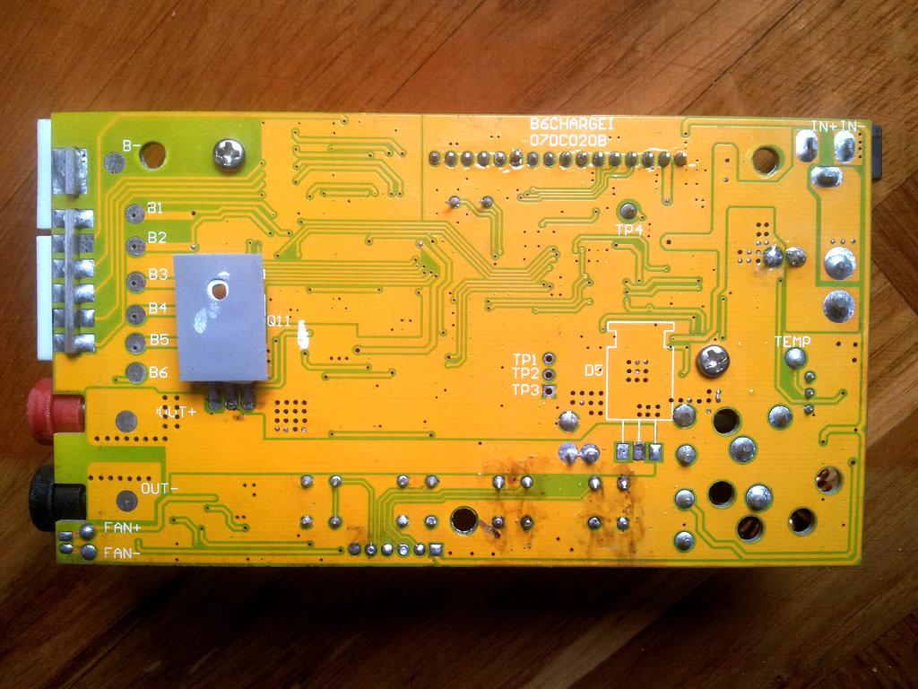
Could you please send few photos of this charger (MB & HW layout)
sorry, I don't have a camera, but my PCB looks exactly like yours.
I'm using coocox CoIDE, it's very easy to use (shame that there is no linux version, I had to install windows ;( )
I will commit my draft code when I get home,
The code will probably be completely rewritten so that it only uses the CMSIS library provided by "nuvoton",
but for now (I'm still learning) it's just easer to use the code generator (repository) provided by coocox.
To write the software UART my code is not necessary,
it would be great if someone could write a simple library with an example that could do something like this:
int main()
{
uart_open(115200);
uart_write("cheali-charger");
}
The code should not use any printf functions.
The "uart_write" function should by non-blocking (should not wait until transmission ends).
There is an example for a software I2C in the "nuvoton" CMSIS library that may be useful:
(M051_Series_BSP_CMSIS_Rev3.00.001/SampleCode/M051-LB_004/I2C_Software_GPIO_Timer).
or maybe there is a open source UART somewhere out there.
Paweł Si
Jun 19, 2014, 10:15:08 AM6/19/14
to cheali-...@googlegroups.com
I've added ARM M0517LBN draft code to github into the "arm_draft" branch.
to download it install "git", run "Git Bash" and type:
~ git clone https://github.com/stawel/cheali-charger.git
~ git checkout arm_draft
in "coIDE":
1. "Project"->"Open Project.." and select "HOME"\cheali-charger\CoIDE\cheali-charger
2. "Project"->"Build"
3. "Debug"->"Debug"
Best Regards
Paweł
sasam
Jun 20, 2014, 3:43:44 PM6/20/14
to cheali-...@googlegroups.com
I've problem with my CoIDE :(
Probably Java problem...
--
BUILD FAILED
Could not launch V:\CooCox\GNU Tools ARM Embedded\4.8 2014q2\bin\arm-none-eabi-gcc: java.io.IOException: Cannot run program "V:\CooCox\GNU Tools ARM Embedded\4.8 2014q2\bin\arm-none-eabi-gcc" (in directory "V:\arm_punjac\cheali-charger\CoIDE\cheali-charger\Debug\obj"): CreateProcess error=5, Access is denied
Total time: 0 seconds
--
Paweł Si
Jun 20, 2014, 3:53:22 PM6/20/14
to cheali-...@googlegroups.com
in: http://www.coocox.org/CooCox_CoIDE.htm
"Note: CoIDE has not integrated GCC compiler. Before using CoIDE, you need to set GCC Toolchain first. Click here to see how to set."
sasam
Jun 20, 2014, 7:18:51 PM6/20/14
to cheali-...@googlegroups.com
Yes I know i set Tool-chain, but it not work. Probably some stupid Java issue.
I try with:
gcc-arm-none-eabi-4_8-2014q2-20140609-win32.exe
& gcc-arm-none-eabi-4_7-2014q2-20140408-win32.exe
same results
Tomorrow i will try on my laptop.
I try with:
gcc-arm-none-eabi-4_8-2014q2-20140609-win32.exe
& gcc-arm-none-eabi-4_7-2014q2-20140408-win32.exe
same results
Tomorrow i will try on my laptop.
Paweł Si
Jun 20, 2014, 7:43:43 PM6/20/14
to cheali-...@googlegroups.com
You should also set the appropriate path to the gcc compiler in CoIDE.
it looks like CoIDE can't find:
"V:\CooCox\GNU Tools ARM Embedded\4.8 2014q2\bin\arm-none-eabi-gcc"
--
sasam
Jun 20, 2014, 8:14:03 PM6/20/14
to cheali-...@googlegroups.com
When i copy command from CoIDE build screen to to GCC command promt, It compile files and produce .o files
I think that setting tollcahin is adjusting gcc path in CoIDE.
I think that setting tollcahin is adjusting gcc path in CoIDE.
Paul Verburg
Jun 21, 2014, 7:47:48 PM6/21/14
to cheali-...@googlegroups.com
Hi,
You guys are racing along I have been off line "sick" and just catching up.
I was thinking of putting serial on a spare uart and leave the temp senor pins alone.
what do you think ? im more than happy to try that ones my bits arrive ?
just let me know.
Paul Verburg
Jun 22, 2014, 6:16:31 AM6/22/14
to cheali-...@googlegroups.com
Update got all the software installed and it looks like it build successfully now waiting on my nulink ................
sasam
Jun 22, 2014, 5:52:44 PM6/22/14
to cheali-...@googlegroups.com
CooIDE work on my laptop (win7) as expected, but on desktop PC (XP windows) still not working.
sasam
Jun 22, 2014, 6:41:12 PM6/22/14
to cheali-...@googlegroups.com
I detected problem on my desktop PC. When i disable "Kerio personal firewall" i can compile from CooIDE.
Paweł Si
Jun 23, 2014, 9:16:34 AM6/23/14
to cheali-...@googlegroups.com
there are free UART pins available on the CPU.
it's also possible to separate the temp. sensor from the 3 pin output connector,
and leave the UART where it is.
sasam
Jun 25, 2014, 6:29:24 PM6/25/14
to cheali-...@googlegroups.com
Finlay I successfully compiled and flashed chealy-charger on my B6 ARM clone :)
First I erase everything with NuMicro ICP programing tool, and then with same tool tray to flash ~\cheali-charger\CoIDE\cheali-charger\Debug\bin\cheali-charger.hex but this file is to large for flash.
After that i try, and successfully compile and flash directly with CoIDE, but when I connected it to power supply it not work. Finally with ICP programing tool I adjusted config bits to 0xF8FFFFFF (switch to external clock) and after that keyboard and display work well.
Finally I have functional development platform.
Is it OK that LDROM is empty?
Message has been deleted
Message has been deleted
Paul Verburg
Jun 26, 2014, 2:57:32 AM6/26/14
to cheali-...@googlegroups.com
On Thursday, June 26, 2014 12:00:38 PM UTC+12, sasam wrote:

Igon
Jun 29, 2014, 8:15:51 AM6/29/14
to cheali-...@googlegroups.com
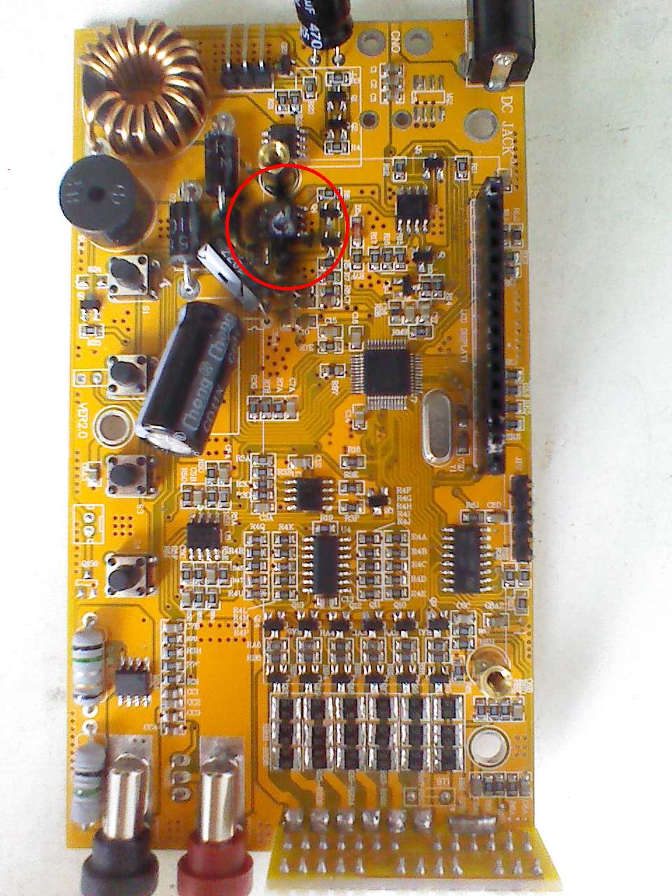
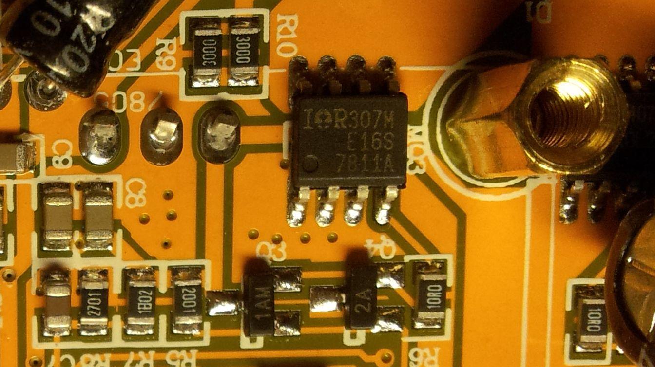
can be IRF7811W
But my PCB is very different from all what I seen here..
My 7811 is connected by all 4 left paws to the diode near the buzzer
My 7811 is connected by all 4 left paws to the diode near the buzzer
Paweł Si
Jun 29, 2014, 5:09:03 PM6/29/14
to cheali-...@googlegroups.com
Thanks,
I added a few changes to the "arm_draft" branch.
I would say that the charger is in a pre alfa stage now,
it should work, but some improvements can still be made:
1. UART - needs to be implemented.
2. ADC:
a) I'm quite impressed, I had to slow down the ADC clock 100x
to get reasonable results (so there is still room for improvements)
b) ADC capacitor discharge (at the multiplexer) - needs to be implemented.
3. PWM - works, but can be improved.
4. LCD - for some reason the refresh rate seems to be slow
(probably it's just a cheap one)
to "pull" the changes just run in "git bash":
>git pull
Have fun, and be careful! yesterday I had a fire in my room ;)

Andrew Frewer
Jun 30, 2014, 4:29:02 PM6/30/14
to cheali-...@googlegroups.com
Hello all, it turns out that my B6AC+ clone from TomTop on ebay is one of the Nuvoton ARM based clones. I took it apart immediately once I got it in the mail today and have been testing it out with some nimh 5 cell packs that I've got.
So far it's working well, but I'm eager to help and or test with this project to port cheali-charger to ARM.
Is this the programmer that I need for my clone: http://www.aliexpress.com/item/Free-Shipping-1SET-Bu-Link-Compatible-Nuvoton-Nu-Link-for-all-Cortex-M0-MINI51-M052-NUC120/1570055317.html
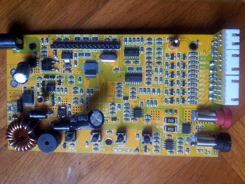
I have the version 2.0 PCB. I've attached a picture.


sasam
Jun 30, 2014, 8:22:17 PM6/30/14
to cheali-...@googlegroups.com
This programer is OK I have one and it work well. Few post before I post one photo with my programer.
My PCB is also V2.0.
My PCB is also V2.0.
Andrew Frewer
Jun 30, 2014, 10:13:18 PM6/30/14
to cheali-...@googlegroups.com
Sasam, did you get yours from aliexpress? Paul's is taking a very long time to get to him.
Currently I'm testing charging nicd batteries with the stock firmware. It doesn't seem to be charging nearly as much as it should...
I know that you are just getting started with programming yours. Have you gotten it to do more that just tests?
Thank you,
Andrew
sasam
Jul 1, 2014, 3:35:26 AM7/1/14
to cheali-...@googlegroups.com
Yes Aliexpres ftom this shop: http://www.aliexpress.com/store/group/Programmer-Emulator/812021_211534006.html
I hope it will be more than just tests :)
I hope it will be more than just tests :)
Andrew Frewer
Jul 1, 2014, 3:29:38 PM7/1/14
to cheali-...@googlegroups.com
Alright. Looks like prices have gone up. I'll pick one up in a few weeks when I have the money... bought an ATMega programmer before I realized I had a Nuvoton clone.
Andrew Frewer
Jul 2, 2014, 12:39:35 AM7/2/14
to cheali-...@googlegroups.com
I don't have any lipos to test but so far my clone is charging nimh and nicd batteries very well. It also has overvoltage protection for the DC input. I tried to plug my 19.5V volt laptop PSU into it to see what would happen (was a little afraid it would kill it) but it just made an unhappy beep at me and said "input voltage fault." For a clone it isn't so bad.
My main complaint is that it doesn't have the auto amp charging that it claims... only manual settings.
Sasam, I hope that your issue with charging nimh batteries isn't a hardware problem!
sasam
Jul 2, 2014, 4:41:28 PM7/2/14
to cheali-...@googlegroups.com
Dana srijeda, 2. srpnja 2014. 06:39:35 UTC+2, korisnik Andrew Frewer napisao je:
I don't have any lipos to test but so far my clone is charging nimh and nicd batteries very well. It also has overvoltage protection for the DC input. I tried to plug my 19.5V volt laptop PSU into it to see what would happen (was a little afraid it would kill it) but it just made an unhappy beep at me and said "input voltage fault." For a clone it isn't so bad.My main complaint is that it doesn't have the auto amp charging that it claims... only manual settings.
Andrew, did you try with original SW or with cheli-charger?
Most of my Lipo is 2S, only one old is 3S. To calibrate all balancer ports I have plan to build something like "calibration bench" at the end of this web page http://www.martinmelchior.be/2013/09/recalibrating-imax-b6-ac-charger.html
Sasam, I hope that your issue with charging nimh batteries isn't a hardware problem!
I hope there was problem with bad calibration.
Yesterday I compile and flash last ARM-cheali-charger sw to may charger, but did not try to charge. I start amiliarizing with SW playing with calibration menu: input voltage & external temp.
Pawel,
Does external temp calibration on last ARM version work properly ?
It seems to me that value range is to small.
I start playing with external temp because it seems to me there is less danger for start :) and it is connected to pin you want to use for serial Tx, and I want to investigate how this part of code work.
Vin: measurement is quite stable. Difference with my voltmeter is 0.06 to 0.07 V (def. calibration in range 10-14V). Calibration work well but I must somewhere check may voltmeter calibration :)
What is correct procedure to debug code. Is it possible to connect charger to power and in same time connect bu-link, and debug with CoIDE ?
When I flash charger I connect only bu-link power without main power to charger, and it work OK on this way.
Andrew Frewer
Jul 2, 2014, 6:46:42 PM7/2/14
to cheali-...@googlegroups.com
Sasam, like I said before I don't have a bulink/nulink programmer so I'm running the stock SW. Please post pictures of your calibration bench if you do end up making one!
Also, could you please post a picture with the programming pins labeled? I know that the one with a square is ground (right?) but that's about it.
It's normal to program without powering the whole thing. The programmers provide enough power for the microchip. :) Same thing when I programmed my FlySky GT3B.
sasam
Jul 2, 2014, 8:47:30 PM7/2/14
to cheali-...@googlegroups.com
Dana četvrtak, 3. srpnja 2014. 00:46:42 UTC+2, korisnik Andrew Frewer napisao je:
Also, could you please post a picture with the programming pins labeled? I know that the one with a square is ground (right?) but that's about it.
I posted it before: https://groups.google.com/group/cheali-charger/attach/2f140ccac893d9e4/jp2_2_CPU_trace_front_02.jpg?part=0.4&authuser=0&view=1
pin description:
1 ICE_DAT
2 ICE_CLK
3 ICE_ RST
4 GND
5 VCC
Bu-link connector description you can find on Aliexpress web shop: http://www.aliexpress.com/store/product/Free-Shipping-1SET-Bu-Link-Compatible-Nuvoton-Nu-Link-for-all-Cortex-M0-MINI51-M052-NUC120/812021_1570055317.html
Andrew Frewer
Jul 2, 2014, 9:54:55 PM7/2/14
to cheali-...@googlegroups.com
Thank you! I thought I had read through the whole thread but I somehow missed it. I'll order a Bulink in the next week or too so I can participate as well. :)
Paul Verburg
Jul 8, 2014, 2:56:46 AM7/8/14
to cheali-...@googlegroups.com
I wonder if you know the hex ID of the 017 mpu my programmer keeps saying chip not found its a kiel link 2 and don't have a 017 option so i used the 016. so was thinking maybe i make my own profile for that chip ?????
sasam
Jul 8, 2014, 5:27:36 AM7/8/14
to cheali-...@googlegroups.com
M0517 is version of M0516 with inacurate internal oscilator
Paul Verburg
Jul 10, 2014, 1:35:42 AM7/10/14
to cheali-...@googlegroups.com
Ok i'm still unable to get the Realview ulink2 to connect to the MPU.
Now have the nuvoton flash board on order to see if I can make that one work.
sasam
Jul 11, 2014, 8:50:51 PM7/11/14
to cheali-...@googlegroups.com
Pawel do you repair your ARM charger?
Few days ago I start playing with CoIDE debugger connected to Bu-link only (without main power). It seems that everything work, even the LCD is usable. Is it safe to connect the main power during a debug session?
For exercise i tray to investigate detail for Texternal calibrate.
Is it posible to increase resolution AD reading for temp sensor? I have LM35 temp sensor (10.0 mV/˚C) and values which is displayed are in relatively short range and not stable. Voltage measurement are much better than temp.
saša
Paweł Si
Jul 12, 2014, 5:47:11 PM7/12/14
to cheali-...@googlegroups.com
Yes
Few days ago I start playing with CoIDE debugger connected to Bu-link only (without main power). It seems that everything work, even the LCD is usable. Is it safe to connect the main power during a debug session?
it should be safe, until you don't start to charge or calibrate the charge/discharge current.
I also accidentally connected the main power and Bu-link at the same time and nothing burned :)
For exercise i tray to investigate detail for Texternal calibrate.
Is it posible to increase resolution AD reading for temp sensor?
no, the ADC is the same for all "inputs", but I'm currently working on it
to increase the stability.
Andrew Frewer
Jul 12, 2014, 10:31:25 PM7/12/14
to cheali-...@googlegroups.com
So, if I'm understanding this, cheali-charger is working on ARM now?
Paweł Si
Jul 13, 2014, 8:39:48 AM7/13/14
to cheali-...@googlegroups.com
2014-07-13 4:31 GMT+02:00 Andrew Frewer <afre...@gmail.com>:
So, if I'm understanding this, cheali-charger is working on ARM now?
almost, the voltage measurement is not as stable as I'd like,
and there is no UART.
and actually it is working only on ARM M0516/M0517 nuvoton CPU,
Andrew Frewer
Jul 13, 2014, 12:28:27 PM7/13/14
to cheali-...@googlegroups.com
Can you tell if it works better than the stock firmware?
Paweł Si
Jul 13, 2014, 1:14:41 PM7/13/14
to cheali-...@googlegroups.com
2014-07-13 18:28 GMT+02:00 Andrew Frewer <afre...@gmail.com>:
Can you tell if it works better than the stock firmware?
I would wait a little, it still needs some work
(especially when it comes to NiMh batteries charging)
.....My main complaint is that it doesn't have the auto amp charging that it claims... only manual settings.
unfortunately cheali-charger doesn't offer any "auto" functionality :/
Andrew Frewer
Jul 13, 2014, 2:29:08 PM7/13/14
to cheali-...@googlegroups.com
Alright. I'm just charging nicd and NiMH cells right now so I'll wait a bit. Stock firmware doesn't seem to like nicds.
sasam
Jul 13, 2014, 4:08:37 PM7/13/14
to cheali-...@googlegroups.com
Dana nedjelja, 13. srpnja 2014. 18:28:27 UTC+2, korisnik Andrew Frewer napisao je:
Can you tell if it works better than the stock firmware?
On my charger cheali-charger its definitely better then stock FW. On stock fw works only Lipo program but with problematic accuracy. All other programs (NiMh, NiCd, Pb) report "connection break" just after charging start.
Paweł Si
Jul 13, 2014, 6:11:52 PM7/13/14
to cheali-...@googlegroups.com
I've add some ADC stability improvements to the repository.
Best Regards,
Paweł
Paweł Si
Jul 15, 2014, 8:36:48 AM7/15/14
to cheali-...@googlegroups.com
2014-07-15 0:46 GMT+02:00 Sasa Mihajlovic <sasa.mi...@gmail.com>:
Hi Pawel,In IO.h you have the same code for enableFuncADC & disableFuncADC
is it OK ?
//based on coocox DrvGPIO
inline void enableFuncADC(uint8_t adc) {
outpw(&SYS->P1_MFP, (inpw(&SYS->P1_MFP) & ~(0x1<<((adc) +8))) | (0x1<<(adc)));
}
inline void disableFuncADC(uint8_t adc) {
outpw(&SYS->P1_MFP, inpw(&SYS->P1_MFP) & ~( (0x1<<(adc+8)) | (0x1<<adc)) );
}
this is the part that enable/disables the ADC on a specific pin.
But the main ADC measurement routine is in src/hardware/[?]/AnalogInputsADC.cpp
there is a table called: "order_analogInputs_on" that contains information
how to read analog data and where to save them
(the measurements are performed "auto-magically" ;) in background),
for example:
reading power supply voltage:
{-1 , V_IN_PIN , AnalogInputs::Vin , false, false},
where:
"-1" - not a multiplexer input
"V_IN_PIN" - read ADC value from this pin
"AnalogInputs::Vin" - where to save the result
reading external temp. sensor:
{MADDR_T_EXTERN, MUX0_Z_D_PIN, AnalogInputs::Textern, false, false},
where:
"MADDR_T_EXTERN" - this is a input from the multiplexer (4051) at adress MADDR_T_EXTERN == 7
"MUX0_Z_D_PIN" - read ADC value from this pin (common for all multiplexed values)
"AnalogInputs::Textern" - where to save the result
Last night i grab you last version and focus on temp sensor measurement.
On room temp (cca 25°C) I have:
0.270V => value fluctuation 3063-3067
when sensor took and warm (dT= cca 8°C) in fingers:
0.351V => value fluctuation 3081-3085when sensor put close to my desktop neon light
0.900V => value fluctuation 3131-3135
hm.. the vales should be in the range 0-65536 it looks like the sensor in not connected
to the multiplexer, I assumed it's exactly like in this schematics (but I have not tested this):
try to replace:
{MADDR_T_EXTERN, MUX0_Z_D_PIN, AnalogInputs::Textern, false, false},
with:
{-1, UART_TX_PIN, AnalogInputs::Textern, false, false},
maybe this will help,
Best Regards,
Paweł
sasam
Jul 15, 2014, 8:03:24 PM7/15/14
to cheali-...@googlegroups.com
last few days I study your "automagical" adc routines. Thereafter start using debugger, I discovered magic in ADC_IRQHandler. Now it is clearer to me how it works.
What are the last two parameters (false, false) in "order_analogInputs_on" config table ?
In my charger Temp sensor is connected directly to pin 45 (&P12). Unfortunately this pin can not be assign as HW uart TX.
Do you have any plan for uart?
Is it safe to set pin 45 as output pin and use it as SW UART_TX_PIN?
In my charger Temp sensor is connected directly to pin 45 (&P12). Unfortunately this pin can not be assign as HW uart TX.
Do you have any plan for uart?
Is it safe to set pin 45 as output pin and use it as SW UART_TX_PIN?
Last night i grab you last version and focus on temp sensor measurement.
On room temp (cca 25°C) I have:
0.270V => value fluctuation 3063-3067
when sensor took and warm (dT= cca 8°C) in fingers:
0.351V => value fluctuation 3081-3085when sensor put close to my desktop neon light
0.900V => value fluctuation 3131-3135hm.. the vales should be in the range 0-65536 it looks like the sensor in not connectedto the multiplexer, I assumed it's exactly like in this schematics (but I have not tested this):try to replace:{MADDR_T_EXTERN, MUX0_Z_D_PIN, AnalogInputs::Textern, false, false},with:{-1, UART_TX_PIN, AnalogInputs::Textern, false, false},maybe this will help,Best Regards,Paweł
Yes it help. Now temp: readings follow value: readings as expected and it is very stable.
Great!
Best Regards,
Saša
Paweł Si
Jul 16, 2014, 5:38:00 AM7/16/14
to cheali-...@googlegroups.com
2014-07-16 2:03 GMT+02:00 sasam <sasa.mi...@gmail.com>:
last few days I study your "automagical" adc routines. Thereafter start using debugger, I discovered magic in ADC_IRQHandler. Now it is clearer to me how it works.
;) your are better then me, It's not always clear to me how it works,
this is a good indicator that something needs to be rewritten.
What are the last two parameters (false, false) in "order_analogInputs_on" config table ?
One of the parameters is not used (should be removed), and the second, see email:
In my charger Temp sensor is connected directly to pin 45 (&P12). Unfortunately this pin can not be assign as HW uart TX.
Do you have any plan for uart?
Is it safe to set pin 45 as output pin and use it as SW UART_TX_PIN?
Yes, I do have a plan: to wait until some implements the software UART :)
(if the plan fails I will do it myself but it won't be this year)
And Yes, it should be safe.
Best Regards,
Paweł
sasam
Jul 16, 2014, 5:58:18 PM7/16/14
to cheali-...@googlegroups.com
In my charger Temp sensor is connected directly to pin 45 (&P12). Unfortunately this pin can not be assign as HW uart TX.
Do you have any plan for uart?
Is it safe to set pin 45 as output pin and use it as SW UART_TX_PIN?Yes, I do have a plan: to wait until some implements the software UART :)(if the plan fails I will do it myself but it won't be this year)And Yes, it should be safe.
OK I will try to do it.
Good exercise for my first programming attempt on microcontroller :)
Is it safe to connect one LED to Tx and GND?
Which timer should I use for that TMR2 or TMR3 ?
0 & 1 are in use?
Do you have any suggestion how to config UART_TX_PIN?
Is it necessary to disable ADC on this pin before config it for output?
For first attempt I can try with one LED connected to Tx, and when learn how to control them i can focus on serial Tx implementation.
Paweł Si
Jul 17, 2014, 7:21:29 AM7/17/14
to cheali-...@googlegroups.com
2014-07-16 23:58 GMT+02:00 sasam <sasa.mi...@gmail.com>:
OK I will try to do it.
Good exercise for my first programming attempt on microcontroller :)
Is it safe to connect one LED to Tx and GND?
hm.. I'm not sure what the Q22 does (it's probably a PNP transistor)
and it is always safer to connect the LED with an resistor (maybe 1K Ohm) in series,
there is also a 10K/10K (?) voltage divider, I'm not sure if it will handle a LED,
but we will know when you try ;)
you may also try to connect it like this (1,2,3 - pins on the plug):
1. Anode
2. Resistor
3. GND (not connected)
cathode connected to the resistor
Which timer should I use for that TMR2 or TMR3 ?
0 & 1 are in use?
TMR2 or TMR3 is ok.
Do you have any suggestion how to config UART_TX_PIN?
if you are using the IO.h header the it should look like this:
IO::pinMode(UART_TX_PIN, OUTPUT);
write "1" to the pin:
IO::digitalWrite(UART_TX_PIN, 1);
write "0" to the pin:
IO::digitalWrite(UART_TX_PIN, 0);
Is it necessary to disable ADC on this pin before config it for output?
I'm not sure, just remove it temporary from AnalogInputsADC.cpp.
Paul Verburg
Jul 17, 2014, 3:34:00 PM7/17/14
to cheali-...@googlegroups.com
Hi I was going to use the uart1 as it is free and leave the external temp sensor so you can have both want to use logview and make sure i don't cook the battery.
I now have bu link and got the first firmware upload working now need to teach my self C
I understand that that is outside the main stream of this project but would fit my need i also trying to workout the schematic around the temp pin its not like the other designs ?
getting to grips with github, C, ARM etc. I'm a pic person and started on a Motorola 6800 some 35years ago so i'm a bit slow.
Paweł Si
Jul 17, 2014, 4:17:36 PM7/17/14
to cheali-...@googlegroups.com
2014-07-17 21:34 GMT+02:00 Paul Verburg <paul.v...@gmail.com>:
Hi I was going to use the uart1 as it is free and leave the external temp sensor so you can have both want to use logview and make sure i don't cook the battery.I now have bu link and got the first firmware upload working now need to teach my self CI understand that that is outside the main stream of this project
no it's not, I will merge both solutions to the project if they will work,
a dedicated UART is something people asked for.
but would fit my need i also trying to workout the schematic around the temp pin its not like the other designs ?
schematic would be great.
getting to grips with github, C, ARM etc. I'm a pic person and started on a Motorola 6800 some 35years ago so i'm a bit slow.
;)
Best Regards,
Paweł
sasam
Jul 17, 2014, 10:13:33 PM7/17/14
to cheali-...@googlegroups.com
hm.. I'm not sure what the Q22 does (it's probably a PNP transistor)and it is always safer to connect the LED with an resistor (maybe 1K Ohm) in series,there is also a 10K/10K (?) voltage divider, I'm not sure if it will handle a LED,but we will know when you try ;)you may also try to connect it like this (1,2,3 - pins on the plug):1. Anode2. Resistor3. GND (not connected)cathode connected to the resistor
I got 1.648V for logical "1" (Tx vs GND), Bu-link power
Is it enough for logical "1" on 3.3V TTL serial?
pin 1. vs 3. = 4.28 V
Do you have any suggestion how to config UART_TX_PIN?if you are using the IO.h header the it should look like this:IO::pinMode(UART_TX_PIN, OUTPUT);write "1" to the pin:IO::digitalWrite(UART_TX_PIN, 1);write "0" to the pin:IO::digitalWrite(UART_TX_PIN, 0);
It works
I wrote few comands to control UART_TX_PIN with UP & DOWN key
I wrote few comands to control UART_TX_PIN with UP & DOWN key
Paweł Si
Jul 18, 2014, 7:58:57 AM7/18/14
to cheali-...@googlegroups.com
2014-07-18 4:13 GMT+02:00 sasam <sasa.mi...@gmail.com>:
I got 1.648V for logical "1" (Tx vs GND), Bu-link power
Is it enough for logical "1" on 3.3V TTL serial?
pin 1. vs 3. = 4.28 V
Do you have any suggestion how to config UART_TX_PIN?if you are using the IO.h header the it should look like this:IO::pinMode(UART_TX_PIN, OUTPUT);
Try to change this line to:
IO::pinMode(UART_TX_PIN, GPIO_PMD_OUTPUT);
you should get 2.5V at "1" state.
This voltage should be enough for a cp2102 USB<->UART dongle
sasam
Jul 18, 2014, 1:41:59 PM7/18/14
to cheali-...@googlegroups.com
I got 1.648V for logical "1" (Tx vs GND), Bu-link power
Is it enough for logical "1" on 3.3V TTL serial?
pin 1. vs 3. = 4.28 V
Do you have any suggestion how to config UART_TX_PIN?if you are using the IO.h header the it should look like this:IO::pinMode(UART_TX_PIN, OUTPUT);Try to change this line to:IO::pinMode(UART_TX_PIN, GPIO_PMD_OUTPUT);you should get 2.5V at "1" state.This voltage should be enough for a cp2102 USB<->UART dongle
Now I have 1.98V for "1"
pin 1 to pin 3 = 4.20V
powerd with Bu-link (4.22V)
It seems that 10K/10K voltage divider is problem here.
sasam
Jul 18, 2014, 3:28:28 PM7/18/14
to cheali-...@googlegroups.com
Now i try with normal power and now i got 2.39V for "1"
Paul Verburg
Jul 18, 2014, 7:09:48 PM7/18/14
to cheali-...@googlegroups.com
Ok need new glasses uart1 tx pin is in use so cant be used for logview.
But I managed to get uart0 tx to work with a demo prog cant see if this pin 5 is used for anything else cant see a track but might be under the MCU ??
when trying to merge it with project it broke it and even removing dint help so back to reloading original project.
At least I have seen "hello world !"
Paweł Si
Jul 18, 2014, 7:37:11 PM7/18/14
to cheali-...@googlegroups.com
2014-07-19 1:09 GMT+02:00 Paul Verburg <paul.v...@gmail.com>:
Ok need new glasses uart1 tx pin is in use so cant be used for logview.But I managed to get uart0 tx to work with a demo prog cant see if this pin 5 is used for anything else cant see a track but might be under the MCU ??when trying to merge it with project it broke it and even removing dint help so back to reloading original project.At least I have seen "hello world !"
nice!
It would be great if you could create:
src/core/ARM-Cortex-M0/Serial.h
src/core/ARM-Cortex-M0/Serial.cpp
in Serial.h should be an object called "Serial"
with methods:
void Serial.begin(unsigned long baud); //initialize uart with speed = baud
void Serial.write(uint8_t c); // send char c through uart (not blocking)
void Serial.flush(); //can be empty
void Serial.end(); //can be empty
it would be also nice if the uart would have a buffer of 256 characters.
if You do that you need to add:
#define ENABLE_SERIAL_LOG
to:
src/hardware/imaxB6-clone-ARM-Cortex-M0/HardwareConfigGeneric.h
and it should work.
Best Regards,
Paweł
Paweł Si
Jul 20, 2014, 1:50:47 PM7/20/14
to cheali-...@googlegroups.com
Hi All,
I have fixed some bugs in NiMH, NiCd battery charging
and also added MCU internal temperature measurement,
all changes are in the "arm_draft" branch.
Best Regards
Paweł
Paweł
Andrew Frewer
Jul 20, 2014, 4:54:59 PM7/20/14
to cheali-...@googlegroups.com
Great! If if ever have any money I'll have to get a Bulink to test it out.
Unfortunately I left my radio at the track yesterday so that's my top priority. :(
Andrew Frewer
Jul 20, 2014, 5:17:08 PM7/20/14
to cheali-...@googlegroups.com
Never mind. Radio was found. Now to find a Bulink.

Андрей Кудрявцев
Jul 26, 2014, 1:19:28 PM7/26/14
to cheali-...@googlegroups.com
Hi, All!
On my win7-x64 it's automatically detected as USB HID device (USB\VID_0416&PID_511B&REV_0100).
Nuvoton NuMicro ICP Programming Tool 1.25 reports "Nu-Link connected (ID: 77888a01)".

CooCox Cortex Flash Programmer didn't connect. Debugging from CoIDE isn't working too.

Any suggestions?
Best Regards,
Andrei
sasam
Jul 26, 2014, 7:27:10 PM7/26/14
to cheali-...@googlegroups.com
On my win7-x64 it's automatically detected as USB HID device (USB\VID_0416&PID_511B&REV_0100).Nuvoton NuMicro ICP Programming Tool 1.25 reports "Nu-Link connected (ID: 77888a01)".
Try to instal last verson of ICP_Programming_Tool: http://www.nuvoton.com/resource-files/NuMicro_ICP_Programming_Tool_V1.26.6314.zip than flash Bu-link with the FW from this version.
Yesterday I had similar problem on my laptop Win 7 (32bit). Currently I am on vacations and I took my laptop, bu-link & charger to play with in spare time. Unfortunately I did not tray Bu-link on my laptop at home and yesterday i discover that I have problem. Problem is solved with this last version.
Best Regards,
Saša
Андрей Кудрявцев
Jul 27, 2014, 1:07:49 AM7/27/14
to cheali-...@googlegroups.com
Saša, thanks for your reply.
воскресенье, 27 июля 2014 г., 6:27:10 UTC+7 пользователь sasam написал:
I've intalled new version of ICP and upgraded Bu-link FW.
No luck, situation is the same. Connected B6 just beeps and show "INPUT VOL ERROR" message.
воскресенье, 27 июля 2014 г., 6:27:10 UTC+7 пользователь sasam написал:
sasam
Jul 27, 2014, 6:32:20 AM7/27/14
to cheali-...@googlegroups.com
I've intalled new version of ICP and upgraded Bu-link FW.No luck, situation is the same. Connected B6 just beeps and show "INPUT VOL ERROR" message.
You have ARM version B6?
Wiring (Bu-link <=> B6) is OK?
look at https://groups.google.com/d/msg/cheali-charger/VATJQ4-GpVE/IReGVD_tXgMJ
What happen when try to connect with ICP programing tool (select "M051 series" and press connect) ?
воскресенье, 27 июля 2014 г., 6:27:10 UTC+7 пользователь sasam написал:On my win7-x64 it's automatically detected as USB HID device (USB\VID_0416&PID_511B&REV_0100).
I have the same USB HW Id for my Bu-link connected on Win7-x32
Андрей Кудрявцев
Jul 27, 2014, 8:17:10 AM7/27/14
to cheali-...@googlegroups.com
воскресенье, 27 июля 2014 г., 17:32:20 UTC+7 пользователь sasam написал:
I've intalled new version of ICP and upgraded Bu-link FW.No luck, situation is the same. Connected B6 just beeps and show "INPUT VOL ERROR" message.
You have ARM version B6?
Yes.
Wiring (Bu-link <=> B6) is OK?
Same as shown.
What happen when try to connect with ICP programing tool (select "M051 series" and press connect) ?
ICP says "Nu-Link connected (ID: 7788635f)". Leds "grn" and "red" blinks. With or without B6, doesn't matter.
When I connect B6 and plug Bu-link to computer, backlight of B6 goes on like loading, but LCD symbols are dim. Connected B6 just beeps and stop on "INPUT VOL ERROR" message.
Then, I start ICP and press "Connect". ICP says the same "Nu-Link connected (ID: 7788635f)". B6 beeps and restarts for every 5 sec? until I press "Disconnect"
It is loading more messages.
0 new messages