Clone iMax B6 SKYRC (80W)

29,079 views
Skip to first unread message

Paul Verburg

unread,
Jul 3, 2014, 1:15:23 AM7/3/14
to cheali-...@googlegroups.com
Specs:
max charge 80W
max Dischr 10W
charge current 0.1-6.0 A
Disch current 0.1-2.0 A
Curr ball lipo 300mah/cell

MPU ????

working on it just want to post the board layout.

Paul V.

Front new board imaxB6 (80W).jpg
Back new board imaxB6 (80W).jpg

Andrew Frewer

unread,
Jul 3, 2014, 2:01:03 AM7/3/14
to cheali-...@googlegroups.com
How much did it cost? Source.

Too bad the chip is blanked out. Noticed they spelled enter as "entor." ;)

Andrew Frewer

unread,
Jul 3, 2014, 2:02:22 AM7/3/14
to cheali-...@googlegroups.com
Oh, and nice nail polish! Just noticed the pink nails. :)

Andrew Frewer

unread,
Jul 3, 2014, 2:03:23 AM7/3/14
to cheali-...@googlegroups.com
Unless those aren't nails and I'm going to look like an idiot.

Paul Verburg

unread,
Jul 3, 2014, 3:21:12 PM7/3/14
to cheali-...@googlegroups.com
ebay
$23.00 AU

and I'm glad you like the colour of the handles of my side cutters.;-)

Andrew Frewer

unread,
Jul 3, 2014, 4:13:10 PM7/3/14
to cheali-...@googlegroups.com
Whoops. D:

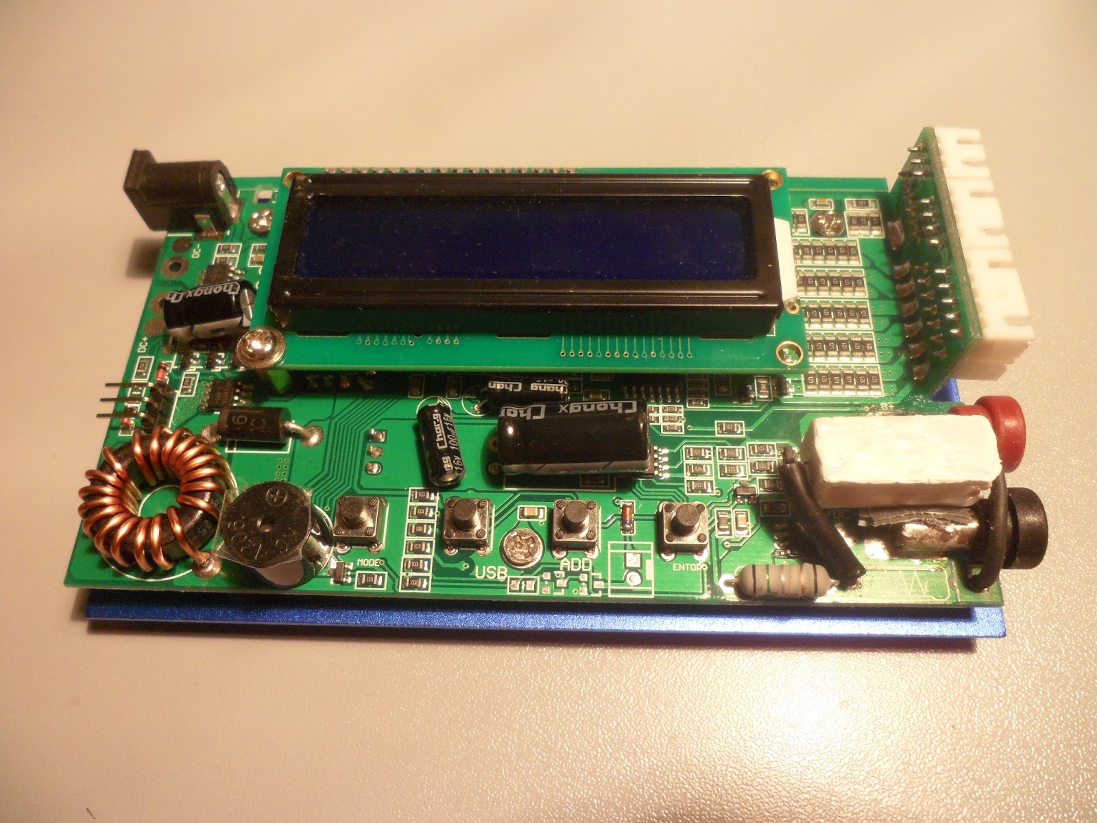
That PCB looks pretty different. With those extra MOSFETs it might actually be capable of 80W.

Paweł Si

unread,
Jul 4, 2014, 6:23:47 PM7/4/14
to cheali-...@googlegroups.com
have you tried to connect a usbasp to the charger?


2014-07-03 21:21 GMT+02:00 Paul Verburg <paul.v...@gmail.com>:
ebay
$23.00 AU

and I'm glad you like the colour of the handles of my side cutters.;-)

hm.. very nice side cutters ;)


Paul Verburg

unread,
Jul 6, 2014, 3:05:15 AM7/6/14
to cheali-...@googlegroups.com
Yes I have no luck tracing the pins found ground and one high pin the rest appears to be at ground level and even with board running no signals at all i traced the xtal cant find a mpu that lines up unless they moved pin 1 by 45drge ??
real bummer i hoped they would be more M051......
will keep tryinging to identify the MPU.
Paul V.

Paweł Si

unread,
Jul 8, 2014, 6:41:33 AM7/8/14
to cheali-...@googlegroups.com
2014-07-06 9:05 GMT+02:00 Paul Verburg <paul.v...@gmail.com>:
Yes I have no luck tracing the pins found ground and one high pin the rest appears to be at ground level and even with board running no signals at all i traced the xtal cant find a mpu that lines up unless they moved pin 1 by 45drge ??
real bummer i hoped they would be more M051......
will keep tryinging to identify the MPU.
Paul V.


It seems to me that this is not a "nuvoton" processor,
as far as I know they don't have 44-pin ARM cpus.
even if it was so, there is no pin layout documentation,
so it would be very difficult to support this chip.
 

AV Sync

unread,
Jul 12, 2014, 3:21:36 AM7/12/14
to cheali-...@googlegroups.com
I have the exact same board. Stock firmware is terrible, really hoping I can save the charger with cheali. Any luck identifying the chip yet?

I've probed out the following so far:

Header (Left to Right)
Header Pin 1 - ?
Header Pin 2 - MCU Pin 38
Header Pin 3 - MCU PIN 39 - GND
Header Pin 4 - ?
Header Pin 5 - MCU Pin 37
Header Pin 6 - MCU Pin 36
MCU Pin 40 - XTAL
MCU Pin 41 - XTAL

Gerhard Schindler

unread,
Aug 31, 2014, 5:45:46 PM8/31/14
to cheali-...@googlegroups.com
Unpacked my new charger ==> I have the same board!

Are there any news about the MCU?

cheers
Gerhard

Ivan Ivanov

unread,
Nov 20, 2014, 1:38:56 PM11/20/14
to cheali-...@googlegroups.com

Hello. I got the same charger. Here sketched some connection. What is this microcontroller?

20-11-2014 21-36-17.jpg

Paul Verburg

unread,
Nov 23, 2014, 2:37:46 PM11/23/14
to cheali-...@googlegroups.com
Hi we still don't know I'm hooping someone will find the pin out and the MPU I have had no luck.

Paul V.  

Albert Llurba

unread,
Nov 27, 2014, 8:32:43 AM11/27/14
to cheali-...@googlegroups.com
Hello, is there any news? I have the same board and it works very badly.

Roman Sand

unread,
Dec 23, 2014, 4:22:41 PM12/23/14
to cheali-...@googlegroups.com
Have same device did someone identify the chip ?
Thanks. 

zapparello

unread,
Jan 5, 2015, 4:46:54 PM1/5/15
to cheali-...@googlegroups.com
Hello!

I have absolutely same charger and I'm trying to find what microcontroller it uses.
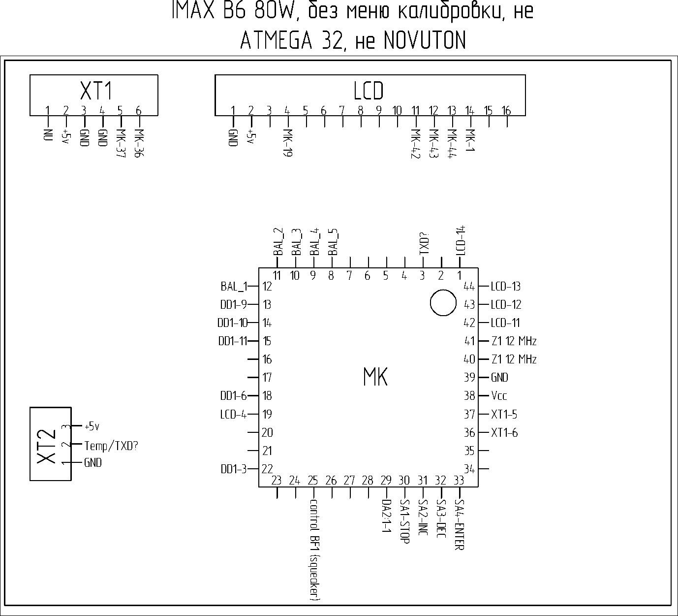
You have a error in your pinout: the XT1 pin 4 is not connected to anything.
Pin 3 is connected to GND, this is correct.

Also one can observe that the right row of pins on the microcontroller (pins 34-44) ressembles very much the pins 1-11 of a regular atmega32.
The crystal is placed at the same pins, GND and VCC are at the same pins, and pins 36 and 37 are "SCK" and "RESET" on atmega32 which is logic to put on the programming connector.
However, MISO and MOSI are not connected to XT1, which is strange.
Also there are no GND/VCC pins along the other three sides of the microcontroller.

So, I suppose this could be some old Atmel microcontroller. Possibly, the chinese guys found a source of some very cheap very old microcontrollers and implemented an IMAX on them.
This is very laudable from nature protection point of view :-]

четверг, 20 ноября 2014 г., 21:38:56 UTC+3 пользователь Ivan Ivanov написал:

Hello. I got the same charger. Here sketched some connection. What is this microcontroller?

Paweł Si

unread,
Jan 5, 2015, 5:54:56 PM1/5/15
to cheali-...@googlegroups.com
Hi guys,
I already gave up the search, but I wish you luck on that!

My guess is that it's a freescale arm cpu,
but repackaged into a "cheaper" socket version
(where "cheaper" refers to license costs ;) )
something like this:
http://www.freescale.com/webapp/sps/site/taxonomy.jsp?code=KINETIS_E_SERIES&cof=0&am=0

I'm also guessing that the XT1 connector is a SWD port:

maybe it would be a good idea to connect a SWD capable JTAG (St-link V2 for example)
to it and check if you get any connection?
 

Best regards and wish you luck!
Paweł

Sergio

unread,
Apr 10, 2015, 5:02:41 PM4/10/15
to cheali-...@googlegroups.com
In my opinion it's an Holtek mcu. HT67F489 seems to match, apart from a 90° rotation of orientation relative to pin n.1.
Vdd and Vgnd match, XTAL matches, analog inputs (balancing voltages) and also the 2 pins for programmer.

Petar Horvat

unread,
May 4, 2015, 2:44:44 AM5/4/15
to cheali-...@googlegroups.com
hi.. did you try it... or did you figure this out only from the pictures.. i have the same chharger.. i would like to test if its a holtek.. i need to calibrate it somehow.. but the usuall button combinations dont work :)

Mindaugas Markauskas

unread,
May 4, 2015, 9:59:47 AM5/4/15
to cheali-...@googlegroups.com
I also have charger with same hardware, but with 50W charging and 10W discharging software. Looking for chanse to rewrite/recalibrate it on first place then it will be posible.

One more thing: my charger enters strange menu then pressing Start and Enter buttons during power on. It's shows voltages of 6 cells (like LiPo balance ports measurments) Does anyone have this menu and having ideo what it means? 

Jiří Holubčík

unread,
May 19, 2015, 3:42:48 PM5/19/15
to cheali-...@googlegroups.com
Hi,
is anybody solve this problem? I have same board with blanked chip and I want to upload Jozsefs firmware.
Thank You

Pritish singh

unread,
Jun 5, 2015, 4:09:09 AM6/5/15
to cheali-...@googlegroups.com

I have 5 chargers with same board,please someone figure out what is this mess.

alex alex

unread,
Jun 5, 2015, 6:39:05 AM6/5/15
to cheali-...@googlegroups.com
Guys, you own those chargers. So the only way is you to take the board and check CPU pins where they go to. It's hard for us (who don't have the board) to to this analysis based on the pictures (if they are provided). So I would expect to see what pin is power and gnd, then pins for programming connector, display connections, balance port connection... as much as you can find. Then we would have something.

Regards.

compucell

unread,
Jun 9, 2015, 6:38:58 PM6/9/15
to cheali-...@googlegroups.com
hi I think I found the  calibration menu hold  Batt.Type (stop) and start (enter) plug power in


On Thursday, 3 July 2014 07:15:23 UTC+2, Paul Verburg wrote:

Eric Flynn

unread,
Jun 9, 2015, 7:19:29 PM6/9/15
to cheali-...@googlegroups.com
I just got one of these as well.  That is not the correct calibration button combination unless they are shipping different firmware versions.  It does not work on mine.

I have tried all button combinations and they do nothing.

I am going to try and track down what the MPU is so we can get them flashed with proper firmware.

compucell

unread,
Jun 10, 2015, 4:13:21 PM6/10/15
to cheali-...@googlegroups.com
Photo of imax b6 clone
           maybe it it a different firmware
20150610_175702.jpg
20150610_175721.jpg
20150610_175753.jpg
Message has been deleted

Pritish singh

unread,
Jun 18, 2015, 2:59:11 AM6/18/15
to cheali-...@googlegroups.com
Guys,I think I found out the MCU of this board,It might be an NXP P87C591.
datasheet: http://www.futurlec.com/Philips/P87C591VFAApr.shtml
It's based on 8-bit 8051 family of MCUs.
First we have to try to dump the firmware from this charger.
sdfsadf.JPG
20-11-2014 21-36-17 (2).jpg

Eric Flynn

unread,
Jun 18, 2015, 12:51:28 PM6/18/15
to cheali-...@googlegroups.com
Pritish,  please study it closer.  I think you are wrong.

andmiller

unread,
Jun 24, 2015, 9:58:03 PM6/24/15
to cheali-...@googlegroups.com
Hey, is there anything I can do to help the search? Have the same charger and it is a piece of junk, I think the new software would help.

alex alex

unread,
Jun 25, 2015, 1:32:21 AM6/25/15
to cheali-...@googlegroups.com

alex alex

unread,
Jun 26, 2015, 1:39:35 AM6/26/15
to cheali-...@googlegroups.com

Eric Flynn 

3:28 PM (17 hours ago)

to me
It appears that the majority of the clones on the shelf now are going to be the unknown MCU.  I have bought 3 "different" chargers now, and they all have it.  It looks as if cheali-charger is to remain useful to its fullest, that a solution needs to be found.

I am going to try to probe out the schematic for it.  I do not think it matches the pic you have there Alex.

If nothing else, I am planning to get an Atmega32 breakout/carrier board, pull the current chip off, and hack in the Atmega32.

The hardware actually seems to be pretty well made, with decent components.  If the shipped software would just allow calibration, it wouldnt be so bad. The calibration as it is shipped is just too bad to use without potentially ruining your cells.

andmiller

unread,
Jun 26, 2015, 11:44:34 AM6/26/15
to cheali-...@googlegroups.com
Eric,
Would something like this work? http://www.hobbyking.com/hobbyking/store/__27195__Atmel_Atmega_Socket_Firmware_Flashing_Tool.html
If it is an atmel MCU, it may be easier than desoldering...

Alex,
Looking through the pictures in the thread, I am sure it is the same.
BTW, I got mine from Banggood.
 Was trying to balance charge 6s and it would never finish, I think the calibration is way off, I am afraid to use it anymore.

Joe Rouvier

unread,
Jun 28, 2015, 7:19:22 AM6/28/15
to cheali-...@googlegroups.com
Indeed, holding down stop and start while powering on does calibrate it.  I've found the best results by feeding 24.75v across the charging point and 4.125v across each of the balancing pins.

You'll also need to supply about 1v to the middle pin of the temperature probe port.  If you don't do this it will abort charging with temp alarms.


On Tuesday, June 9, 2015 at 3:38:58 PM UTC-7, compucell wrote:

andmiller

unread,
Jun 28, 2015, 10:37:45 AM6/28/15
to cheali-...@googlegroups.com
Joe, I could not get this to work. When it goes into calibration mode, the voltages start off about 4.16 and goes to 4.19-4.2 and just stays there. It does the same whether anything is connected or not. Any other suggestions?

Joe Rouvier

unread,
Jun 30, 2015, 3:39:41 AM6/30/15
to cheali-...@googlegroups.com
Couple things to note:

* Regardless of what voltage it sees during calibration, it's going to call that 4.2v.  If you give it 3v, then it's going to think 3v is 4.2v
* There is a small amount of leakage current in the balance port (as with just about everything containing a semiconductor).  If you don't connect anything to the balance port, and leave it floating, it's going to see a voltage there

Here's the circuit I used to calibrate mine:


PS1 was sourced from my bench power supply
R1 - R6 are 2k 25-turn trimmer pots, but just about any value should work
U1 - U5 are RC4558 op-amps (actually 3 chips since the the RC4558 is a dual op-amp)
C1 - C6 are 1F caps in parallel with 1uF Poly caps
C8 is a 100uF, which is probably way more than what you need

The above circuit is far from ideal, it's just what I had on hand.  I used the RC4558's because they can survive a dead short on their output.  The 1F caps simulated a battery enough that I could trick the charger into trying to charge / discharge, so I didn't have to disconnect everything after calibration and hook up a battery before I could to see the resulting voltage readings after calibration.

You could instead do this:


All the trimmer pots (except the temp calibration one) are now plain 'ol resistors.  Since the charger itself is throwing things off, I'd try to use as low value resistors as possible.  six 100-ohm 0.1% 1/4w resistors would run you about $1.14 from digikey (part #A105969CT-ND ).  The Caps could be any size, 1uF is probably fine, but you'd want low-leakage.

-Joe

Pritish singh

unread,
Jul 1, 2015, 12:42:47 AM7/1/15
to cheali-...@googlegroups.com
Guys,there is no calibration mode in our chargers,I've tried all combinations.How are you even calibrating?

Mindaugas Markauskas

unread,
Jul 1, 2015, 1:51:51 AM7/1/15
to cheali-...@googlegroups.com
Thank you for circuits, going to try it definitely. My situation is what then i entered calibration mode using STOP+START combination without calibration nominal connected i ruined all the readings. After during then all voltages becomes incorrect in all charging modes. After i conected +25.2V into charging output i got correct reading on charging Nimh, NiCd and Pb batteries, but LiPo charging was incorrect. Charger done 1S  cell on 4.20, but in reality cell was charger only 3.5V.

Yesterday i tried to calibrate using 10% 100R resistors in your circuit (nothing to lose for me now), so I've got now thing better a litthe bit but not in right direction. Without finishing charging i've saw that cell hes more voltage then charger shows. So 0.1% resistors are necessary for me to finish all the calibration. To the note, i tested may 100R resistors and all of them was 116R in reality, so them are out of specs for 10% measurements. In circuit i had connected about 4.5V per balance port, so logically calibration supposed to end wrong in first place :)

alex alex

unread,
Jul 1, 2015, 3:58:54 AM7/1/15
to cheali-...@googlegroups.com
I've heard that some chargers were calibrated once at the factory and don't allow a second time calibration. The same happened to me. So I uploaded the cheally charger firmware. 

Mindaugas Markauskas

unread,
Jul 1, 2015, 4:17:56 AM7/1/15
to cheali-...@googlegroups.com
I could enter this calibration mode as much as i want. I think this is for this hardware+firmware only.

Joe Rouvier

unread,
Jul 1, 2015, 1:32:47 PM7/1/15
to cheali-...@googlegroups.com
Hmm, it shouldn't matter if all your resistors are 116 or 100, as long as they are all the same.  The absolute value of them shouldn't matter, only the ratio between them.  However, if just one of them is off, it will throw off everything.

Was the voltage on the circuit 4.5V with or without the charger connected?  It's possible that your charger is throwing off the circuit more than expected.


--
You received this message because you are subscribed to the Google Groups "cheali-charger" group.
To unsubscribe from this group and stop receiving emails from it, send an email to cheali-charge...@googlegroups.com.
For more options, visit https://groups.google.com/d/optout.

Mindaugas Markauskas

unread,
Jul 2, 2015, 12:19:16 AM7/2/15
to cheali-...@googlegroups.com
Tomorrow i'm getting thous .1% precision resistors anyway. I think 4.5V was before I powered charger, but with it connected. One more thing i'am going to do if resistors will not helps is to lower thous 25.2V till i get 4.2V for balance ports. But i think this would be problem for main charging leads, because voltage will be low here too.

andmiller

unread,
Jul 7, 2015, 9:02:51 AM7/7/15
to cheali-...@googlegroups.com
What about using 6 properly charged lipos? I think this did not work for me before, because you had said 24.75V in a previous post, will try with the higher voltage.
Thanks,

Morten Schmidt

unread,
Jul 26, 2015, 10:17:59 AM7/26/15
to cheali-charger
How do you save or complete the calibration? I have the circuit with 6 resistors connected and am supplying 25.2V (each voltage is around 4.19-4.20v) and can enter same menu by holding start+stop, and it shows 6 balance readings, but I'm not sure it saves anything.

After powering off and trying charging, it still reads 4.2v on balance ports but only 8.2v on main screen while in CV phase of charging. 4.2+4.2 should not be 8.20...

I guess I will try charging some old cells and see if they end up closer to 4.2v without getting overcharged, just wondering if I am doing the calibration right or there is another step needed to do the overall voltage calibration.

Morten Schmidt

unread,
Jul 27, 2015, 5:35:31 PM7/27/15
to cheali-charger, morten.s...@gmail.com
To update, after the START+STOP balance calibration my charger now slightly under charges in balance mode (4.16-4.17v per cell - charger displays 4.20v per cell and 8.20V overall). So seems calibration is stored automatically (simply pull power cord to end calibration). 

But in non-balance or one-cell charge mode, it overcharges (4.25V while charger  displays 4.10V), just like before calibration (before calibration it would overcharge in both balance and non-balance mode). I am charging in Li-Ion mode which should charge to 4.1V according to manual. It seems the calibration carried out is only for balance ports, not main output. There must be another hidden menu to calibrate main port.

Also, I had strange problem with discharging after calibration - a 1S3P pack will only discharge at 0.4A (as reported on charger display). Only 1.5W discharge. Did any of you who did the calibration notice problems with discharging after?

Morten

Morten Schmidt

unread,
Jul 30, 2015, 11:32:35 AM7/30/15
to cheali-charger, morten.s...@gmail.com
OK, I played some more with the charger. By supplying 4.1 per balance port instead of 4.2 seems to have brought the accuracy closer, but current calibration is seriously shot. Then charger says it supplies 3.0A, I get between 1.42 to 1.47A. 

Same problem with discharging, discharge current is less than half what charger displays, and pack capacity is reported at more than double what real capacity is. 
(Discharging a 2S pack can be done at 1.2A (hittting the 10W limit if that 1.2A was real. Not sure why it wouldn't discharge a 1S pack at more than 0.4A).

Has anybody ended up with a usable charger of this type (Start+Stop to calibrate) after attempting to calibrate it? Please share exactly what you did.

Thanks,
Morten

alex alex

unread,
Jul 31, 2015, 2:33:48 AM7/31/15
to cheali-charger, morten.s...@gmail.com
Hi Morten,

I haven't have any experience with this particular charger, nor with balancing with START+STOP combination. But from I've read on other forums they supply exactly 4.2 volts on each balance port. I don't remember any other options.
In your case, whether this is different from others, and you should know exactly how to calibrate as per manufacturer design, or something is broken in your charger ( I would dig into this and maybe would change some ICs).

If everything is ok with the hardware, then there is one other method of fixing it by determining the right values for some resistors and change them, thus calibrating it at the hardware level. Here are more details about it http://members.home.nl/marion.ben/Instructions%20for%20upgrading%20Imax%20B6%20charger%20V2.doc. Here is a guy who did this http://forum.rcdesign.ru/f8/thread189907-34.html#post5517686. Here there are some details about how to calibrate the second port http://forum.rcdesign.ru/f88/thread139479-49.html#post2750737.

Hope it helps.

Глазков Евгений

unread,
Aug 2, 2015, 6:12:20 AM8/2/15
to cheali-charger
2015_03_25_(18-14-51-68).jpg

Joe

unread,
Aug 14, 2015, 2:11:02 PM8/14/15
to cheali-charger
I just bought this exact model from Amazon and I wanted to tinker as well. Firmware is really sloppy. I polled the pins and I came up with the following:

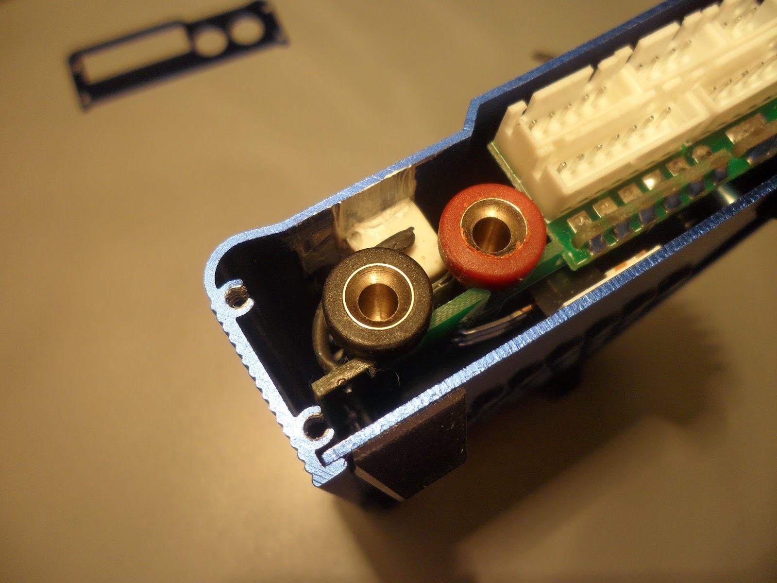
From Left-to-right like yours:
Pin 1 = Float(Not GND)
Pin 2 = VCC(5v)
Pin 3 = RST(5v Active Reset)
Pin 4 = Float(Not GND)
Pin 5 = GND
Pin 6 = GND

I say float because you can't use it as a ground for pin 2. I feel like it is tri-stated and may need a pull-up or it is activley held low by the MCU. Worst case, disabled pins for debug mode.
I ran out of wick and I don't have anything around to make my LCD socketed. I will have to gather a few supplies. Has anyone tried to poll the 5 USB pads under the DEC button? Maybe hook a cable up to windows and see if it finds a device(asks for drivers) or shows a resource IO tree. I will give that a go, can't hurt. If I find a PCI_VEN it would point us in the right direction.

On Saturday, July 12, 2014 at 3:21:36 AM UTC-4, AV Sync wrote:
I have the exact same board. Stock firmware is terrible, really hoping I can save the charger with cheali. Any luck identifying the chip yet?

I've probed out the following so far:

Header (Left to Right)
Header Pin 1 - ?
Header Pin 2 - MCU Pin 38
Header Pin 3 - MCU PIN 39 - GND
Header Pin 4 - ?
Header Pin 5 - MCU Pin 37
Header Pin 6 - MCU Pin 36
MCU Pin 40 - XTAL
MCU Pin 41 - XTAL

Grzegorz S

unread,
Aug 25, 2015, 4:29:43 AM8/25/15
to cheali-charger
I tried STM32 ST-LINK Utility by my ST-LINKv2 dongle without succes :(. 

I can send you this board for science :) if you want.

W dniu poniedziałek, 5 stycznia 2015 23:54:56 UTC+1 użytkownik cheali-charger napisał:
Hi guys,
I already gave up the search, but I wish you luck on that!

My guess is that it's a freescale arm cpu,
but repackaged into a "cheaper" socket version
(where "cheaper" refers to license costs ;) )
something like this:
http://www.freescale.com/webapp/sps/site/taxonomy.jsp?code=KINETIS_E_SERIES&cof=0&am=0

I'm also guessing that the XT1 connector is a SWD port:

maybe it would be a good idea to connect a SWD capable JTAG (St-link V2 for example)
to it and check if you get any connection?
 

Best regards and wish you luck!
Paweł

priv...@gmail.com

unread,
Sep 8, 2015, 11:07:59 PM9/8/15
to cheali-charger
what about this?

ATMEL 
XMega A4U TQFN-44

Grzegorz S

unread,
Sep 10, 2015, 4:09:04 AM9/10/15
to cheali-charger
I've probed out the following so far:

Header (Left to Right)
Header Pin 1 - ?
Header Pin 2 - MCU Pin 38
Header Pin 3 - MCU PIN 39 - GND
Header Pin 4 - ?
Header Pin 5 - MCU Pin 37
Header Pin 6 - MCU Pin 36
MCU Pin 40 - XTAL
MCU Pin 41 - XTAL

 
what about this?

According to http://www.atmel.com/images/Atmel-8387-8-and16-bit-AVR-Microcontroller-XMEGA-A4U_Datasheet.pdf pinout doesn't match.

XMega pin 39 is Vcc, our MCU pin 39 is GND
XMega pin 38 is GND, our MCU pin 38 is unknown
XMega pins 36 and 37 are XTAL but our MCU XTAL pins are 40, 41.

This looks like in mirror. 

dekzz

unread,
Sep 19, 2015, 5:00:35 PM9/19/15
to cheali-charger
Hi guyz,
I bought the exact same chager as the photos of 1-st post. Since i knew I got the clone i opened it at once. I've read other forums and  If ound out that not the schematic, nor the firmware are the same as the original or of the other clones. Firstly I fond out that voltages are not real (suppose not calibrated) and I tried to enter the orignal service menu bu holding start+dercrease whle power on, but nothing happened. I tried randomly combination until I got the start+end + power until got the 6s grid menu. Since then I lost my charger. Tough is hardware malfunction cuz I got the silicon smell and verry hot case. Voltage readings were about 45-48 volts per single 1s cell?!!! After 4-5-6 calibration menu enterings I got 1.06 volts per 5s battery!!?!!!? Then I hooked 6s almost charged battery at balance port and plug charging cord at charger via XT60 plug into the charger then holded start+cancel and powered on. The 4.20V appeared at the screen at all 6 positions. Plugged off fhe grid. After powering on I tried NIMH, LIPO 1s and 5s and all voltages were within 1% tolerance with my FLUKE precision voltmeter. Glad I saved the clone. Tough is for the garbage. Now everything is fine, exept on discharge - the higher the voltage, the lower the current. At 5s got nax 0.4A, at 6s max 0.3A discharge current... I dont remember if this was in the beggining since I almost "fried" the brand new charger in "software" way. Hope I was in help of s.o. Be well!
Greetings!

Juha-Matti Sidorow

unread,
Oct 2, 2015, 4:31:20 AM10/2/15
to cheali-charger
Have you noticed that USB text on PCB (bottom)? Possible to use skyrc software?

Juha-Matti Sidorow

unread,
Oct 8, 2015, 9:41:26 AM10/8/15
to cheali-charger
there is low quality picture of pcb with some extra components.


i guess those transistors and one rsestor is for fan or something, not usb.

dfly

unread,
Oct 29, 2015, 3:51:58 AM10/29/15
to cheali-charger
OMG!!!
this works perfect for my charger!!! 
it started charging crazy hi on #3, i bought a flasher but after checking pins realised I only have 4! and the mysterious USB pads.
i had put it away and was using a real charger..until i touched a connector to the case and lost the magic smoke ...
and really needed this one.
i used charged (4.16) 500mah batteries on my breakout cable; it would balance 2 at a time before i bought the new one so I managed to top up a set.
after pressing "stop" and "enter" on power up I got a display with 6 voltages flashing around until they all stopped at 4.20. i powered down. and up and 
its charging a 3s perfect now!!!!
I'm totally afraid to do this again in case it's a "one time menu".
thanks so much dekzz

Juha-Matti Sidorow

unread,
Nov 6, 2015, 9:13:41 AM11/6/15
to cheali-charger

Here is pins traces.


Andrzej Lalek

unread,
Nov 10, 2015, 6:08:01 AM11/10/15
to cheali-charger
I also have that charger! and I found something like this:

Could it be that chip? 

Juha-Matti Sidorow

unread,
Nov 13, 2015, 10:55:52 AM11/13/15
to cheali-charger
No, pinout doesn't match.

Paul Paku

unread,
Nov 21, 2015, 4:47:57 PM11/21/15
to cheali-charger
Hi,
I have just got this sh...t and tried to get it calibrated using resistors.
The problem is that charger is hard looped now  like:  LiPo6 Discharge mode >> battery check >> "Connection Error" message.
And can not change this behaviour.
All I can do is just enter start/stop calibration but nothing changing on the LCD. It's not entering so called "calibration" ...\

Any ideas ??

Paul Paku

unread,
Nov 21, 2015, 5:21:11 PM11/21/15
to cheali-charger


Case seems be the same and not so common...

Juha-Matti Sidorow

unread,
Dec 3, 2015, 3:27:38 AM12/3/15
to cheali-charger
That SAA7120H; SAA7121H is

Digital video encoder

:)

Mickaël Quirin

unread,
Dec 3, 2015, 2:30:12 PM12/3/15
to cheali-charger
Hi
I have the exact same behavior.
Tried all button before searching the web and found the calibration menu (without anything hook up in the balance port)
I did it again with lipo on 6S port and it show 2.80~ on each cell (they're about 4,15 each).
And' when I turn it on normally it loop on the lipo discharge mode 3S (9V) and its like the enter button was stuck (whick is not since i need to push it to enter calibration mode).
If a battery is connected it show overvoltage and connection error if nothing is plugged in (make sense).

slyfox net

unread,
Dec 6, 2015, 8:27:57 AM12/6/15
to cheali-charger
Здравствуйте!. Имею точно такую же зарядку на неизвестном процессоре. И тоже как и все пытался откалибровать и попал в сервисное меню. Вы уже нашли способ выхода из этой ситуации - или еще нет?. Если нет- могу помочь!

четверг, 3 июля 2014 г., 8:15:23 UTC+3 пользователь Paul Verburg написал:

slyfox net

unread,
Dec 9, 2015, 6:57:18 AM12/9/15
to cheali-charger

slyfox net

unread,
Dec 17, 2015, 9:39:04 AM12/17/15
to cheali-charger

Читаем внимательно! Что не понятно – спрашивайте. Объясню все что знаю. Ковыряю всего неделю- поэтому могут быть ошибки и дополнения.!


Ну вот и я как и все кто хотел подешевле стал обладателем этого китайского чуда- клона imax b6  на неизвестном процессоре, с неизвестной 

прошивкой да еще и без коммутатора 4051. Лучше или хуже хрен знает , говорят с прогревом данная микросхема дрейфует и измеренное 

напряжение плывет. У меги 32 ножек не хватало  или АЦП шек, а тут неизвестный проц и вроде все хватает. Пошли китайцы по упрощенному 

пути. Ну и как всегда хотелось улучшить китайское творение. Стандартное сервис меню в этом клоне не доступно. Но поигравшись с кнопками 

 и включением и выключением- я , как и все попал в него. И думал что ничего страшного- ничего трогать не буду- просто выйду из него. Но 

выхода из него нет, только выключение. Со всеми сброшенными настройками и константами получили почти кирпич. А нехрен лазить шаловливыми 

ручонками. Но ладно - а что же делать дальше?


Читаем.


В двух словах- что произошло. При нажатии двух кнопок stop+ enter и подачи питания зарядка пытается откалиброватся от подключенных 

батарей через семи контактный разъем для балансировки на 6 батарей. Это понятно. Далее при включении - она пытается замерить напряжение 

со всех банок под нагрузкой ( около 24,5) вольт, включается разрядка на 10 секунд. Это у всех одинаково. А вот далее  у всех по разному 

- я считаю это баг в программе. Она пытается измерить напряжение на одной- двух - трех - четырех- пяти - или шести банок в зависимости 

от того какое значение стояло в разрядке Lipo(1s)(2s)(3S) и т.д. до момента нажатия кнопок входа в сервис и если условие не соблюдается  - 

виснет на этом, не реагируя на кнопки. Наша задача сделать так- что бы все условия соблюдались -  и о чудо - зарядка оживает, выходит из 

меню и реагирует на кнопки, но могут быть сбиты константы и она неправильно все будет измерять.  

 Теперь о том что нужно сделать для этого правильно и что бы не пошел дымок из зарядки.

1. Раздобыть где то 6 литиевых батарей 3.7-4.2 вольта и зарядить их. Идеально до одинакового значения. Я 6 штук соединил параллельно и 

подал на них с блока питания 4.1-4.2 вольта контролируя ток чтоб не превышал. Главное напряжение- при 4.3-4.5 в батарее сработает защита 

и она сдохнет. Во общем не важно как вы их зарядите. желательно одинаково.

2. Соединить их последовательно и подключить к разъему (6S) плюс питание( плюс на плюс- минус на минус) как обычно вы их заряжаете.

3. Входим в сервис режим  нажатием двух кнопок stop+ enter. На дисплее отобразится вольтаж по банкам что то около 3.2 - 3.5 вольт что 

нормально, несмотря на то что батареи заряжены на 4.2 вольта.

4. Выключаем зарядку - Теперь ВНИМАНИЕ - если не хотите чтоб пошел дым из нее отключите пока  разъем (6S). Неизвестно в каком режиме она 

включится после выключения.

5. Зарядка включится на разряд всех 6(должна 6, а может и 1 и 2 и т.д.) банок - 10 сек, после этого она захочет замерить напряжение их всех.

6. Это как раз тот баг который надо  обойти. Маленькое отступление. Если ее нужно откалибровать в штатном режиме , то нужно было в о всех

 режимах Lipo выставить (6S), (хотя бы в разрядке 6S) но мы то не знаем что у нас там было. И зарядка пытаясь измерить напряжение с 1 (2,3,4,5 батарей) - получает 22 вольта со всех батарей и виснет с надписью слишком высокий вольтаж. Что мы делаем в этом случае - на все 1 секунда. Когда она пытается измерить напряжение сначала разряжает батарею(или несколько) 10 секунд- она пишет на дисплее сколько  батарей- если(6S) - то ничего делать не нужно, а вот если 1S-2S-3S-4S-5S быстро переносим красный, плюсовой крокодил на плюс того аккумулятора ( или не переносим а начинаем

с него - 1(2,3,4,5) аккумулятора), который указан и через секунду – две-три – обычно десять  (как на дисплее высветится) обратно на 22 вольта (на все аккумуляторы) когда надпись на дисплее изменится на измерение опять всех 6 банок и их балансировку. Если все сделано правильно и вы успели- зарядка уйдет в балансировку 6 банок (так задумал производитель при подключенном  балансировочном разъеме) или в ошибку ,Но ОНА ЗАРАБОТАЕТ. То есть будет реагировать на кнопки входить в меню и т.д. Но может врать  напряжение. Если не успели - пробуйте еще раз. Далее надо калибровать.

Например -у кого пишет РАЗРЯДКА и 1S в левом нижнем углу делаем так: Уже были в сервис режиме и измерили напряжение всех банок.

Балансировочный разъем пока не подключаем! 6 аккумуляторов соединенные последовательно.

Красный и черный крокодил на первом аккумуляторе, Включаем зарядка включается на разряд 10 сек -держим 10 секунд, на разрядке 4 вольта,

 а когда разряд кончится и идет измерение всех банок - на дисплее меняется надпись- есть 1 секунда  переносим на все аккумуляторы красный

 то есть подаем  22 вольта на  нее, (красный переносим на последний аккумулятор). Она потестит и выйдет из режима в балансировку или ошибку.

 И заработает.


Для тех кто не совсем понял!


Как задумал калибровку производитель- это мои домыслы. Выставляем в меню LiPo  везде (6S). Подключаем 6 заряженных и сбалансированных ( 

эталонных) аккумуляторов на заряд + балансир. Нажимаем 2 кнопки в меню. смотрим надписи по банкам. Выключаем. Ничего не отсоединяя 

включаем. Она все делает сама и если видит в конце разбалансировку аккумуляторов встает в режим балансировки из которого выходим кнопкой 

стоп. Все.


Теперь когда мы знаем как калибровать. Калибруем.

Как я калибровал. Да все просто - после того как оживил зарядку - даже если она врет напряжение то все равно ею можно разрядить или 

зарядить все 6 аккумуляторов. Контролируя по эталонному  вольтметру. Изменяя общее напряжение на всех аккумуляторах от 24,2 до 25,2 

зарядив или разрядив их входим в сервис. Вкл. Выкл. Вкл. ожидаем конца - смотрим напряжение на дисплее если оно отличается от вольтметра и 

показывает больше чем на вольтметре, разряжаем аккумуляторы  на 0,2-0,4 вольта и производим повторную калибровку. Я зарядил их до 

25.2 вольта и потихоньку калибровал разряжая. у меня получилось около 24.8 вольт на аккумуляторах по эталонному вольтметру, на дисплее 

24,9- 25,2. Что считаю достаточным. Небольшой запас в минус 0,2-0,4 вольта на погрешности.


Из за чего может пойти дым.


1. Из за переполюсовки сразу- со всеми резисторами. В сервис режиме нет проверки на переполюсовки. А 

калибровка происходит под нагрузкой через 20 омные резисторы и 0.5 тоже да еще 25вольт от лития. Пшик - и нет зарядки. шина 120 ом горит 

сразу причем вместе с дорожками.

2.Не отключенный разъем балансировки при выходе из 1(первого) сервиса ( черт его знает что она делает при первом включении и какие 

параметры у вас ранее стояли, вы ведь случайно как и я в сервис режим попали =)) ) 

3. Когда я долго разряжал все 6 банок с 25.2 до 24 вольт на не откалиброванной зарядке - сгорел (почему-то z44 и был тут же заменен на 

IRFz3205 (по параметрам в 2 раза лучше), полевик заряда(вот тут я вообще не понял почему) пару мелких транзисторов ну и конечно 0,5 

резистор. (похоже был плохой контакт в балансировочном разъеме).

4. Перепутаете что нибудь  в балансировочном  разъеме, отвалится контакт одной из батарей или силовой +или – отвалится- может пойти дымок.


И еще самое главное - В РАЗЪЕМЕ (6S) должен быть хороший контакт!!! При плохом контакте зарядку невозможно откалибровать, она меряет напряжение под нагрузкой!

Ну вот как-то так.

alex alex

unread,
Dec 17, 2015, 1:58:26 PM12/17/15
to cheali-charger
Thanks for sharing this. It's a little too long, and hard to understand everything with translation but the idea is clear.
Message has been deleted

Филчерд Хэнкс

unread,
Dec 23, 2015, 11:34:56 AM12/23/15
to cheali-charger
In this post I describe how to replace discharging resistor. See bottom of post.

slyfox net, огромное спасибо за подробный мануал. Сам таким же образом запорол заводские настройки, пытаясь выяснить есть ли у этого хлама меню калибровки. При чём заводские настройки были очень точные, но любопытной Варваре... Жаль народ заранее никак не предупредить.
По поводу темы хотел добавить, что в моём случае после выхода из меню калибровки и рестарта - никаких действий не последовало. А входил Я в меню несколько раз. Так же ничего не изменилось и после калибровки на самостряпном говностенде. Ну и на дымок намёков не было.
Говорят же - скупой платит дважды. Погнался за дешевизной и купил это дерьмо. Надо было оригинал брать.

А теперь к тому, почему же наш девайс полный хлам.
Для тех, кто использовал iMax как измеритель ёмкости, не является секретом, что он жутко воняет при разрядке. Я по началу не предавал этому значения, но потом понял в чём же дело, когда вдруг прибор стал врать по току разрядки - реальный стал меньше в 10 раз того, что на дисплее. Взглянув в потроха Я сразу понял в чём дело. Сгорел токоизмеряющий резистор. Для такого мелкого резистора это и не удивительно. Поэтому, если вы будете разряжать аккумуляторы iMax-ом, то настоятельно рекомендую сменить этот резистор на более мощный. Я использовал 5W; 0.51 Ohm. По приборам ток с таким шунтом измеряется точно. Ну и расположил Я его между банановыми мамами, подложив изоленту снизу и смазав сверху термопастой для контакта с корпусом. Тестовый прогон показал отсутствие сильного нагрева резистора и как следствие - вони.
Ну и фотографии.

If you want to use this iMax for discharging batteries it's desirable replace this marked resistor. It's necessary to prevent burning out this resistor due to its low dissipation power. I burned it's when discharge 3S 12V Li-Ion battery.
Attention! In my device resistor color code of this resistor was incorrect. By colors it's meant approx 18 Ohm, but in fact it was 0.5 Ohm!!! I check it through soldered onto 3.3 Ohm resistor and see - displayed by iMax current was more than measured current. If you not sure what resistance is true, you can do it as me.
I bought standard 5W 0.51 Ohm resistor and replace the old one.
Then I place it between banana mamas and rubbed thermal paste on top of resistor. Thats all.

Hint: If you want extract buttons without harm to device, you can pull up buttons by tweezers or pliers when device assembled. They are safely disconnected from the small onboard buttons, but do not overdo it.)


Jake Stewart

unread,
Dec 25, 2015, 12:21:16 AM12/25/15
to cheali-charger
Wonder what the "974" on the MCU means?
I tried contacting some suppliers on alibaba, but they refused to tell me the MCU type, saying it was their "confidential info".
If I had the cash, I'd order a shipping container full of them and have them held at the port as counterfeit goods until they produced everything including source code.

Albert Reusen

unread,
Dec 26, 2015, 1:37:03 PM12/26/15
to cheali-charger


Op zaterdag 21 november 2015 22:47:57 UTC+1 schreef Paul Paku:
 I have exactly the same problem.

You already have a solution?

I try them all.

can someone describe me exactly how the calibration should be performed?

I have 6 resistors in series placed and supplied with voltage (4.2V per cell)
also connected to the output of the charger.
1v on the temp input.
Power up with pressure and end stop.
the screen with the sixth voltage is shown (6 x 3.2)
otherwise nothing happens.
Pressing any button has changed nothing.

After disconnecting and removing all the wires still the same problem.

The problem is That charger is hard looped like: LiPo6 Discharge mode >> batterycheck >> "Connection Error" message.
And can not change this behavior.

anyone a solution?

alex alex

unread,
Dec 26, 2015, 10:10:02 PM12/26/15
to cheali-charger
Hi Albert, have you tried what slyfox sugested ? He says that after you see 3.2v in calibration menu, you turn it off, remove the balance port and turn it on. Now it should enter into discharge mode... and then do the trick with voltage checking. Does it do the same for you?

Albert Reusen

unread,
Dec 27, 2015, 8:41:30 AM12/27/15
to cheali-charger


Op zondag 27 december 2015 04:10:02 UTC+1 schreef alex alex:
Hi Albert, have you tried what slyfox sugested ? He says that after you see 3.2v in calibration menu, you turn it off, remove the balance port and turn it on. Now it should enter into discharge mode... and then do the trick with voltage checking. Does it do the same for you?


what do you mean, and then do the trick with voltage checking? 

Albert Reusen

unread,
Dec 27, 2015, 8:51:10 AM12/27/15
to cheali-charger


Op zondag 27 december 2015 14:41:30 UTC+1 schreef Albert Reusen:


Op zondag 27 december 2015 04:10:02 UTC+1 schreef alex alex:
Hi Albert, have you tried what slyfox sugested ? He says that after you see 3.2v in calibration menu, you turn it off, remove the balance port and turn it on. Now it should enter into discharge mode... and then do the trick with voltage checking. Does it do the same for you?


what do you mean, and then do the trick with voltage checking? 


I try to translate the text of slyfox but that fails me
via google translate to the Dutch unit offers an incomprehensible text. 

Albert Reusen

unread,
Dec 27, 2015, 10:33:19 AM12/27/15
to cheali-charger


Op zondag 27 december 2015 14:51:10 UTC+1 schreef Albert Reusen:
thanks for the tip. The charger works again.
still calibration.

I read the text carefully and read again.
then tried what I thought I had read.

waaaaaaaaaaaaaaaaaaaaaaaaaaaaaaaaaaaaaaaw

It works.

thanks 

alex alex

unread,
Dec 28, 2015, 1:33:26 AM12/28/15
to cheali-charger
Hi Albert,

I see you managed to fixed it, still I will try to answer your question for others (because it took me time to understand what he's talking about).
So he says, that before entering the calibration mode is very important to know what was the latest pack (1s - 6s) in the discharge programme. It would be troublesome if it is not 6s! Anyway you need to know whether it is 1s, 2s,... or 5s in order to do "the trick". If it is 6s then there is nothing to do and the calibration goes flawless.
So you get this 4.2v 6s pack (or resistor divider whatever), connect it to the charger, then holding power and start buttons pressed turn the power on (well this is all as usual). The charger shows 3.2v on each channel, disregard this (though, maybe this charger expects 3.2v 6s bank as input, not 4.2? I don't know. slyfox says to disregard this). Then turn it on. And if you don't want to burn your charger (It might) disconnect the 6s port from the charger (next step is to power up it and you never know what the charger will do). Now power up the charger and it should try to discharge your pack for 10 seconds. Now, if you have 6s selected before, it will try to discharge for 10 seconds, measure the voltage and all done. If you have something different than 6s then you need to spot when the charger tries to measure the voltage. Though you have 6s connected to it, it is trying to measure what you had before callibration in discharge programme. So, if you have 1s there, you'll need to connect the red terminal to 1s, let it measure the voltage, and then quickly put it back on to the positive terminal of your 6s pack (I have never done this, I'm just translating.

 Hope this is useful.

222Viktor

unread,
Jan 5, 2016, 1:49:35 PM1/5/16
to cheali-charger
Доброе время можете помочь если Вы с Москвы? 

воскресенье, 6 декабря 2015 г., 16:27:57 UTC+3 пользователь slyfox net написал:

yasha nechepaev

unread,
Jan 6, 2016, 2:31:22 PM1/6/16
to cheali-charger
Читай чуть выше есть описание на нашем просмотри.

вторник, 5 января 2016 г., 20:49:35 UTC+2 пользователь 222Viktor написал:

yasha nechepaev

unread,
Jan 6, 2016, 2:36:41 PM1/6/16
to cheali-charger
писал Slyfox net .Прочти его описание

среда, 6 января 2016 г., 21:31:22 UTC+2 пользователь yasha nechepaev написал:

222Viktor

unread,
Jan 6, 2016, 2:50:59 PM1/6/16
to cheali-charger
Здравствуйте! Вот пытаюсь по Вашей инструкции то отсчёт идёт то ни идёт десяти секундный 

вторник, 5 января 2016 г., 21:49:35 UTC+3 пользователь 222Viktor написал:

222Viktor

unread,
Jan 6, 2016, 2:53:00 PM1/6/16
to cheali-charger
Здравствуйте! Вот пытаюсь по Вашей инструкции то отсчёт идёт то ни идёт десяти секундный 

воскресенье, 6 декабря 2015 г., 16:27:57 UTC+3 пользователь slyfox net написал:
Здравствуйте!. Имею точно такую же зарядку на неизвестном процессоре. И тоже как и все пытался откалибровать и попал в сервисное меню. Вы уже нашли способ выхода из этой ситуации - или еще нет?. Если нет- могу помочь!

222Viktor

unread,
Jan 6, 2016, 3:59:14 PM1/6/16
to cheali-charger
теперь не пищит синие тобло и надпись при включении  загрузочная весит и не на что не реогирует


воскресенье, 6 декабря 2015 г., 16:27:57 UTC+3 пользователь slyfox net написал:
Здравствуйте!. Имею точно такую же зарядку на неизвестном процессоре. И тоже как и все пытался откалибровать и попал в сервисное меню. Вы уже нашли способ выхода из этой ситуации - или еще нет?. Если нет- могу помочь!

slyfox net

unread,
Jan 7, 2016, 5:18:00 AM1/7/16
to cheali-charger
222viktor   дуй сюда, http://forum.rcdesign.ru/f63/thread239077-31.html    и расскажи о своей проблеме.  Обсудим.

Дмитрий Владимирович

unread,
Jan 9, 2016, 6:50:59 AM1/9/16
to cheali-charger
Доброе время суток. Намучился я с калибровкой imax 80W может добрый человек поможет! Проблема следующая: после калибровки по инструкции с 6s разъемом прибор работает нормально,но не может завершить зарядку 1s (одного акб 18650) там где ток - пишет 0.0А, время идет а завершение заряда с надписью Full не появляется, причем тестер показывал напряжение до 4.35 и такое подозрение если не остановить он и дальше будет перезаряжать. А несколько последовательно соединенных акб заряжате и выключает правильно... Я в замешательстве, прошу помощи!

222Viktor

unread,
Jan 9, 2016, 7:23:37 AM1/9/16
to cheali-charger
Спасибо вроде как ожил ща пробую аки гонять смотрю как работает .

четверг, 7 января 2016 г., 13:18:00 UTC+3 пользователь slyfox net написал:

alex alex

unread,
Jan 10, 2016, 1:00:18 PM1/10/16
to cheali-charger
Hi,

try to use balance port when charging 1s batteries. It should improve voltage readings and maybe this will fix your issue.

Regards,

Juha-Matti Sidorow

unread,
Feb 3, 2016, 3:57:28 AM2/3/16
to cheali-charger
Is it possible that this 80W version with unknown MCU use FTDI to program chip instead AVR?

pins 3-4 are probably tx/rx but 2,5 are gnd. 6 maybe vcc, 1 reset or sck. Can some one check with oscilloscope?


perjantai 6. marraskuuta 2015 16.13.41 UTC+2 Juha-Matti Sidorow kirjoitti:

Here is pins traces.


Diogo Carvalho

unread,
Feb 3, 2016, 4:51:21 AM2/3/16
to cheali-charger
You have here the schematic of Imax B6 clone with unknown MCU.
ImaxB6_clone.pdf

Juha-Matti Sidorow

unread,
Feb 3, 2016, 5:56:46 AM2/3/16
to cheali-charger
Ok, thanks for schematic!

Maybe this works?


If there is bootloader and this is atmega with special package

Juha-Matti Sidorow

unread,
Feb 3, 2016, 7:03:17 AM2/3/16
to cheali-charger


so PIN 6 is reset and 3-4 rx/tx ? 1 = vcc, 2-5 = gnd

Diogo Carvalho

unread,
Feb 3, 2016, 9:11:07 AM2/3/16
to cheali-charger
Yes could be that pins. But I doubt that the MCU is an atmega.

Juha-Matti Sidorow

unread,
Feb 4, 2016, 2:02:52 AM2/4/16
to cheali-charger
I tried to communicate with ttl pins 3-4, but no luck. These pins are constantly high state. "reset" pin also does nothing.

Juha-Matti Sidorow

unread,
Feb 4, 2016, 8:29:10 AM2/4/16
to cheali-charger
I removed MCU and tried to open it (crack it) with no success. There is "e1201" mark in package corner "spot", but that doesn't mean nothing. This charger is now scrap.


Diogo Carvalho

unread,
Feb 4, 2016, 9:16:37 AM2/4/16
to cheali-charger
Buy an Atmega32 adapt the connections and you have a working charger ;)

Paweł Si

unread,
Feb 4, 2016, 10:53:57 AM2/4/16
to cheali-charger

2016-02-03 10:51 GMT+01:00 Diogo Carvalho <diogoc....@gmail.com>:
You have here the schematic of Imax B6 clone with unknown MCU.

Nice work!

i'm wondering, why pins: 1, 44,43,42 are connected to LCD_D7 (D6,D5,D4) and connector JP1 doesn't use them?

Diogo Carvalho

unread,
Feb 4, 2016, 11:06:06 AM2/4/16
to cheali-charger
Hum it is a mistake. The LCD_D0 to LCD_D7 are connected to JP1

Juha-Matti Sidorow

unread,
Feb 5, 2016, 2:08:17 AM2/5/16
to cheali-charger
If someone can change code to match this pcb little bit closer, i can try. I can re-route some traces. Atmega32 cost only ~1$ at ebay, so it is cheap experiment.

Juha-Matti Sidorow

unread,
Feb 5, 2016, 3:13:36 AM2/5/16
to cheali-charger
What is this unknown mcu's socket?

Juha-Matti Sidorow

unread,
Feb 5, 2016, 8:43:39 AM2/5/16
to cheali-charger
I make picture where atmega32 is placed to this pcb and rotate it 90 degrees to right


Paweł Si

unread,
Feb 5, 2016, 8:58:11 AM2/5/16
to cheali-charger
2016-02-05 8:08 GMT+01:00 Juha-Matti Sidorow <jus...@gmail.com>:
If someone can change code to match this pcb little bit closer, i can try. I can re-route some traces. Atmega32 cost only ~1$ at ebay, so it is cheap experiment.

based on the schematics you need a MCU with at least 12 ADC inputs, atmega32 is not enough 
It is loading more messages.
0 new messages