Bone VDD_3V3EXP Disable Issues

4,601 views
Skip to first unread message

Andrew Bradford

unread,
Oct 25, 2012, 5:07:11 PM10/25/12
to beagl...@googlegroups.com
If I disable LDO3 in the TPS65217, VDD_3V3A should turn off. VDD_3V3A
turning off should disable U8 linear regulator causing VDD_3V3EXP to
turn off.

It doesn't.

Disabling LDO3 in the TPS65217 causes VDD_3V3A to drop to approximately
2.4 V. This is not low enough to disable the U8 linear regulator's
enable pin. Further, disabling LDO4 after this only causes VDD_3V3A to
drop to approximately 1.2 V. Again, this is not enough to disable U8
linear regulator's enable pin.

I've tested on an A3 and an A6 bone.

I realize there's grave impacts to disabling LDO3 or LDO4, ie: much of
the board won't work any more although the ARM core and DDR will still
be operating. That's OK for my experiments.

How can I turn off VDD_3V3EXP from software without completely turning
off all rails on the TPS65217? Is it possible?

I'm trying to do this in order to debug an issue we see with a custom
cape at power down when running on 3.7 V lithium battery. With our cape
attached, VDD_3V3EXP latches on even when the rest of the BeagleBone is
powered off. This is due to SYS_5V staying present due to the battery
and U8 linear regulator not powering down before the latch action
occurs. The TPS65217 and AM3359 are both in the proper states, I can
boot due to power button press once in the OFF state (defined by the
TPS65217 data sheet). But keeping VDD_3V3EXP running will ruin the
battery life while in the OFF state.

On the cape, we pull up to VDD_3V3EXP for things like MMC/SD and I2C.
I believe this is part of the problem as there may be power back feeding
through the pull-ups enough to cause the latch situation. But we
believe we're following the recommended pull-up strategy documented in
the Bone SRM.

Has any one else seen issues like this when attempting to enter the
TPS65217 OFF state with capes attached that use pull-ups to VDD_3V3EXP
while running on 3.7 V lithium battery power? If so, what capes work?

Yes, I realize this is quite a corner case. Sadly, it's an important
one for me.

Thanks,
Andrew

Gerald Coley

unread,
Oct 25, 2012, 5:13:48 PM10/25/12
to beagl...@googlegroups.com
You are correct. This is something we just ran into yesterday and we are looking at a solution. The solution is being tested and will not be something that shows up in the near future, but hopefully soon. It MAY be something that could be done with a wire mod, but it is too early to tell. Should know more by Monday.

Gerald

Andrew Bradford

unread,
Oct 25, 2012, 5:23:33 PM10/25/12
to beagl...@googlegroups.com, ger...@beagleboard.org
On Thu, 25 Oct 2012 16:13:48 -0500
Gerald Coley <ger...@beagleboard.org> wrote:

> You are correct. This is something we just ran into yesterday and we
> are looking at a solution. The solution is being tested and will not
> be something that shows up in the near future, but hopefully soon. It
> MAY be something that could be done with a wire mod, but it is too
> early to tell. Should know more by Monday.

Thanks! So I'm not crazy, that's good to know. :)
Even if the wire mod is complex, it'd be great if you could share it.

anderse...@gmail.com

unread,
Dec 18, 2013, 5:38:21 PM12/18/13
to beagl...@googlegroups.com, ger...@beagleboard.org, and...@bradfordembedded.com
I ran into a similar finding on the A6 board.  Interestingly, the A5C works correctly.  These are with a battery connected.

I'm investigating a proper shutdown and power-off if the main 5V is removed.  I have a Li-Ion battery connected to keep everything running until a proper shutdown/power-off can occur.
Using the method in "Re: [beagleboard] Chip power down and PMIC_POWER_EN" while in Uboot, I can see that the A5C shuts everything down including the VDD_3V3B supply (see schematic).  The A6 does not.

Now if there is no battery connected, they both power-off.

So what's happening?

Brad

Gerald Coley

unread,
Dec 18, 2013, 7:35:24 PM12/18/13
to anderse...@gmail.com, beagl...@googlegroups.com, Andrew Bradford
Did you look here?


3) Moved the enable for the VDD_3V3B regulator to VDD_3V3A rail. Change was made to reduce the delay between the ramp up of the 3.3V rails. No evidence of this being an issue, but it really needs to be as close to the same as possible.

So, you have to shutdown VDD_3V3A to shutdown the VDD_3V3B.

Gerald

Gerald Coley

unread,
Dec 19, 2013, 10:43:03 AM12/19/13
to Brad Andersen, beagl...@googlegroups.com, Andrew Bradford
The change only affected when the 3V3B rail was enabled by enabling it with the 3V3A rail. So, I can't see how they are related. Both LDOs are powered by the same SYS_5V bus.

What is the level of the SYS_5V bus?

The battery in this case is now supplying all of the LDOs and switchers. So I am thinking that maybe we need to make sure all rails are actually tuned off via SW.

Gerald


On Thu, Dec 19, 2013 at 9:26 AM, Brad Andersen <br...@lite-check.com> wrote:

Thanks for replying.


Yes I have seen that note.  And when the battery is not connected the VDD_3V3A does shutdown, but not when a battery is connected (A6 version).  When I measure the voltage on VDD_3V3A after the ‘shutdown’, it is about 2.4V (it is 3.3V when ON).  Is there a path for leakage back to that node that is keeping the voltage up?


The registers in the PMIC are the same for both board versions.  I have not changed them from what comes with the BBB.


I used this method to test the shutdown:

Uboot example:

  1. Boot to the uboot prompt by pressing any key before the kernel boots
  2. Set the PMIC i2c status register to turn OFF when EN line goes down. (i2c, memory write, device 24, address A, value 0x80)
    > i2c mw 24 A 80
  3. Set the memory base to the RTC registers
    > base 44e3e000
  4. Enable PWR_ENABLE_EN bit (memory write, offset address 98, value in hex 0x00010000)
    > mw 98 10000
  5. Enable ALARM2 interrupt once (memory write, offset address 48, value in hex 0x00000010)
    > mw 48 10
  6. Copy over RTC current time to ALARM2 times for hour/day/month/year (memory copy, from address 8, to address 88, 4 times)
    > cp 8 88 4
  7. This next part is where it gets slightly more complicated because you are going to manually set the ALARM2 minutes to one or two minutes after the current time.
    1. Read the current seconds, minutes. This is easy to manually do because they are in BCD and not in hex. (memory display, address zero, 2 times)
      > md 0 2
      44e3e000: 00000008 00000011    (8 seconds, 11 minutes)
    2. Write to the ALARM2 minutes (seconds should already be zero) (memory write, address 84, value 0x00000012)
      > mw 84 12 (12 minutes)
  8. Wait until the current time catches up to the ALARM2 time and the system will power down. If you took too long doing step 7.2 and the time has already passed, just do step 7.2 again.
    1. While you're waiting you can keep checking the current time ( this will show all 6 fields, second, minute, hour, day, month, year)
      > md 0 6
    2. And if you think you have passed your ALARM2 time you can compare above results with ALARM2 time. If so, go to step 7.2. If you went onto a new hour, you might have to start from step 6.
      > md 80 6

Thanks,

Brad

Brad Andersen

unread,
Dec 19, 2013, 10:26:42 AM12/19/13
to Gerald Coley, beagl...@googlegroups.com, Andrew Bradford

Did you look here?

Gerald Coley

unread,
Dec 19, 2013, 11:05:58 AM12/19/13
to Brad Andersen, beagl...@googlegroups.com, Andrew Bradford
Check the registers in the datasheets. There is a away to group which rails are up and down when you go into the power down  mode. However, it changes back to default when you power back up so you have to write them again..

Gerald


On Thu, Dec 19, 2013 at 10:01 AM, Brad Andersen <br...@lite-check.com> wrote:

The SYS_5V bus has the Battery supply, approx. 3.8V


How can I make sure “all rails are actually turned off via SW”?


I’ll go through the procedure and measure all the voltages and report back.

Brad Andersen

unread,
Dec 19, 2013, 11:01:30 AM12/19/13
to Gerald Coley, beagl...@googlegroups.com, Andrew Bradford

The SYS_5V bus has the Battery supply, approx. 3.8V


How can I make sure “all rails are actually turned off via SW”?


I’ll go through the procedure and measure all the voltages and report back.


Brad


From: Gerald Coley [mailto:ger...@beagleboard.org]

Sent: Thursday, December 19, 2013 7:43 AM
To: Brad Andersen

Brad Andersen

unread,
Dec 19, 2013, 11:55:44 AM12/19/13
to Andrew Bradford, Gerald Coley, beagl...@googlegroups.com
This is without a cape and it is with the BB Black. That's probably why I
was confused about the dates and board versions you referred to.

Brad

-----Original Message-----
From: Andrew Bradford [mailto:and...@bradfordembedded.com]
Sent: Thursday, December 19, 2013 8:50 AM
To: Brad Andersen
Cc: 'Gerald Coley'; beagl...@googlegroups.com
Subject: Re: [beagleboard] Bone VDD_3V3EXP Disable Issues

On 12/19/2013 11:01 AM, Brad Andersen wrote:
> The SYS_5V bus has the Battery supply, approx. 3.8V
>
>
>
> How can I make sure "all rails are actually turned off via SW"?
>
>
>
> I'll go through the procedure and measure all the voltages and report
back.

Are you running a cape during your tests or not?
If so, does your cape have any pull-up resistors on it?

Are we talking about white or black bones? I've lost that in this
conversation. My original experiments were all with white bones.

Thanks,
Andrew

PS: Please keep me CC'ed, I'm no longer subscribed to the list.
> 1. Boot to the uboot prompt by pressing any key before the kernel boots
> 2. Set the PMIC i2c status register to turn OFF when EN line goes down.
> (i2c, memory write, device 24, address A, value 0x80)
>> i2c mw 24 A 80
> 3. Set the memory base to the RTC registers
>> base 44e3e000
> 4. Enable PWR_ENABLE_EN bit (memory write, offset address 98, value in
> hex 0x00010000)
>> mw 98 10000
> 5. Enable ALARM2 interrupt once (memory write, offset address 48, value
> in hex 0x00000010)
>> mw 48 10
> 6. Copy over RTC current time to ALARM2 times for hour/day/month/year
> (memory copy, from address 8, to address 88, 4 times)
>> cp 8 88 4
> 7. This next part is where it gets slightly more complicated because
> you are going to manually set the ALARM2 minutes to one or two minutes
> after the current time.
>
> 1. Read the current seconds, minutes. This is easy to manually do
> because they are in BCD and not in hex. (memory display, address zero,
> 2
> times)
>> md 0 2
> 44e3e000: 00000008 00000011 (8 seconds, 11 minutes)
> 2. Write to the ALARM2 minutes (seconds should already be zero) (memory
> write, address 84, value 0x00000012)
>> mw 84 12 (12 minutes)
>
> 8. Wait until the current time catches up to the ALARM2 time and the
> system will power down. If you took too long doing step 7.2 and the
> time has already passed, just do step 7.2 again.
>
> 1. While you're waiting you can keep checking the current time ( this
> will show all 6 fields, second, minute, hour, day, month, year)
>> md 0 6
> 2. And if you think you have passed your ALARM2 time you can compare

Andrew Bradford

unread,
Dec 19, 2013, 11:49:55 AM12/19/13
to Brad Andersen, Gerald Coley, beagl...@googlegroups.com
On 12/19/2013 11:01 AM, Brad Andersen wrote:
> The SYS_5V bus has the Battery supply, approx. 3.8V
>
>
>
> How can I make sure "all rails are actually turned off via SW"?
>
>
>
> I'll go through the procedure and measure all the voltages and report back.

Are you running a cape during your tests or not?
If so, does your cape have any pull-up resistors on it?

Are we talking about white or black bones? I've lost that in this
conversation. My original experiments were all with white bones.

Thanks,
Andrew

PS: Please keep me CC'ed, I'm no longer subscribed to the list.

> From: Gerald Coley [mailto:ger...@beagleboard.org]
> Sent: Thursday, December 19, 2013 7:43 AM
> To: Brad Andersen
> Cc: beagl...@googlegroups.com; Andrew Bradford
> Subject: Re: [beagleboard] Bone VDD_3V3EXP Disable Issues
>
>
>
> The change only affected when the 3V3B rail was enabled by enabling it with
> the 3V3A rail. So, I can't see how they are related. Both LDOs are powered
> by the same SYS_5V bus.
>
>
>
> What is the level of the SYS_5V bus?
>
>
>
> The battery in this case is now supplying all of the LDOs and switchers. So
> I am thinking that maybe we need to make sure all rails are actually tuned
> off via SW.
>
>
>
> Gerald
>
>
>
>
>
> On Thu, Dec 19, 2013 at 9:26 AM, Brad Andersen <br...@lite-check.com> wrote:
>
> Thanks for replying.
>
>
>
> Yes I have seen that note. And when the battery is not connected the
> VDD_3V3A does shutdown, but not when a battery is connected (A6 version).
> When I measure the voltage on VDD_3V3A after the 'shutdown', it is about
> 2.4V (it is 3.3V when ON). Is there a path for leakage back to that node
> that is keeping the voltage up?
>
>
>
> The registers in the PMIC are the same for both board versions. I have not
> changed them from what comes with the BBB.
>
>
>
> I used this method to test the shutdown:
>
> Uboot example:
>
> 1. Boot to the uboot prompt by pressing any key before the kernel boots
> 2. Set the PMIC i2c status register to turn OFF when EN line goes down.
> (i2c, memory write, device 24, address A, value 0x80)
>> i2c mw 24 A 80
> 3. Set the memory base to the RTC registers
>> base 44e3e000
> 4. Enable PWR_ENABLE_EN bit (memory write, offset address 98, value in
> hex 0x00010000)
>> mw 98 10000
> 5. Enable ALARM2 interrupt once (memory write, offset address 48, value
> in hex 0x00000010)
>> mw 48 10
> 6. Copy over RTC current time to ALARM2 times for hour/day/month/year
> (memory copy, from address 8, to address 88, 4 times)
>> cp 8 88 4
> 7. This next part is where it gets slightly more complicated because
> you are going to manually set the ALARM2 minutes to one or two minutes after
> the current time.
>
> 1. Read the current seconds, minutes. This is easy to manually do
> because they are in BCD and not in hex. (memory display, address zero, 2
> times)
>> md 0 2
> 44e3e000: 00000008 00000011 (8 seconds, 11 minutes)
> 2. Write to the ALARM2 minutes (seconds should already be zero) (memory
> write, address 84, value 0x00000012)
>> mw 84 12 (12 minutes)
>
> 8. Wait until the current time catches up to the ALARM2 time and the
> system will power down. If you took too long doing step 7.2 and the time has
> already passed, just do step 7.2 again.
>
> 1. While you're waiting you can keep checking the current time ( this
> will show all 6 fields, second, minute, hour, day, month, year)
>> md 0 6
> 2. And if you think you have passed your ALARM2 time you can compare

Brad Andersen

unread,
Dec 19, 2013, 2:04:36 PM12/19/13
to Gerald Coley, beagl...@googlegroups.com, Andrew Bradford

Ok, here’s what I did:


No cape

Debug serial connected to desktop computer


1.       Connect battery as designed

a.       Batt+ to TP5

b.      Batt+ to TP6

c.       10k between TP7 and TP8

d.      Gnd to TP8

2.       Connect +5V to power plug

3.       Let BBB boot up

4.       Login

5.       Disconnect +5V

6.       Dump PMIC registers (in order) (same for both boards)

a.       0xE2

b.      0x3E

c.       0

d.      0

e.      0xB1

f.        0x80

g.       0xB2

h.      0x01

i.         0

j.        0

k.       0x80

l.         0

m.    0x7F

n.      0x0C

o.      0x18

p.      0x02

q.      0x09

r.        0x06

s.       0x09

t.        0x38

u.      0x26

v.       0x3F

w.     0x7F

x.       0

y.       0x03

z.       0x15

aa.   0x5F

bb.  0x32

cc.    0x40

dd.  0x20

ee.  0

7.       Shutdown –r now

8.       Boot to Uboot prompt

9.       “i2c mw 24 a 80” (set PMIC status register to turn OFF when PMIC_POWER_EN goes down)

10.   “base 44e3e000”

11.   “mw 98 10000”

12.   “mw 48 10”

13.   “cp 8 88 4”

14.   “md 8 4”

15.   “md 88 4” to check that the data transferred

16.   “md 0 2”

17.   “mw 84 xx”, time in future for Alarm2 to act

18.   Wait for the shutdown

19.   Measure voltages:

a.       A6:

                                                               i.      Vbatt = 4.03

                                                             ii.      SYS_5V = 4.00

                                                            iii.      VDD_5V = 0

                                                           iv.      VDD_3V3B = 3.39

                                                             v.      VDD_3V3A = 2.27

                                                           vi.      VDDS_DDR = 0

                                                          vii.      VDD_MPU = 0

                                                        viii.      VDD_CORE = 0

                                                           ix.      VDD_1V8 = 0.16

                                                             x.      VRTC = 0.16

                                                           xi.      VDD_3V3AUX = 0.16

b.      A5C

                                                               i.      Vbatt = 4.03

                                                             ii.      SYS_5V = 4.03

                                                            iii.      VDD_5V = 0

                                                           iv.      VDD_3V3B = 0

                                                             v.      VDD_3V3A = 0

                                                           vi.      VDDS_DDR = 0

                                                          vii.      VDD_MPU = 0

                                                        viii.      VDD_CORE = 0

                                                           ix.      VDD_1V8 = 0

                                                             x.      VRTC = 0

                                                           xi.      VDD_3V3AUX = 0


So those are my results.  Any thoughts?

Brad Andersen

unread,
Jan 30, 2014, 12:34:51 PM1/30/14
to beagl...@googlegroups.com, and...@bradfordembedded.com
An update:

For the A6 (Beaglebone Black) version, I connected U4 pin 1 (enable) back to VDD_3V3AUX (same as A5C).  It now shuts down correctly while on battery.  This was verified on two A6 BBB.

The mystery is what causes the VDD_3V3A to hang up on the A6 version when shutting down while on battery.

Darren McInnes

unread,
May 11, 2014, 10:15:21 AM5/11/14
to beagl...@googlegroups.com, and...@bradfordembedded.com
Brad,

Thank you for this post. I thought I was going madder than usual when the production units wouldn't turn off but the prototypes did!

all it required was lifting pin 1 of U4 and soldering a wire-wrap wire to the power led anode (side furthest from the edge of the board)

you have as they say "saved my bacon"

Best Wishes,

Darren

Terry

unread,
Jun 26, 2014, 4:01:02 PM6/26/14
to beagl...@googlegroups.com, and...@bradfordembedded.com
Does anyone know if there is a software solution to this issue?  I haven't seen any changes in the recent hardware revisions to address this.  We are currently planning on deploying a couple of dozen BBB and I would prefer not having to make hardware mods.

Terry

John Syn

unread,
Jun 26, 2014, 10:53:36 PM6/26/14
to beagl...@googlegroups.com

From: Terry <smit...@gmail.com>
Reply-To: "beagl...@googlegroups.com" <beagl...@googlegroups.com>
Date: Thursday, June 26, 2014 at 1:01 PM
To: "beagl...@googlegroups.com" <beagl...@googlegroups.com>
Cc: <and...@bradfordembedded.com>
Subject: [beagleboard] Re: Bone VDD_3V3EXP Disable Issues

Does anyone know if there is a software solution to this issue?  I haven't seen any changes in the recent hardware revisions to address this.  We are currently planning on deploying a couple of dozen BBB and I would prefer not having to make hardware mods.
I’ve just been looking into the PMIC for another user and this is probably a configuration issue. The PMIC supports several modes (page 15 of the TPS65217C datasheet). I believe the PMIC isn’t configured to enter OFF mode, but rather it is entering SLEEP mode which means any rails not controlled by the power-down sequencer will remain enabled in SLEEP mode. 

Here is what I think the solution might be:

Add "pmic-shutdown-controller" as shown in
/Documentation/devicetree/bindings/regulator/tps65217.txt.

In the V3.15.1-bone2 kernel, /drivers/mfd/tps65217.c line 213, the
comments “Set the PMIC to shutdown on PWR_EN toggle”. This should work for all kernel V3.8 onwards.

Reading “Power Down Sequence” on page 18 (TPS65217C datasheet), this will initiate the power
down sequence and leave the PMIC in OFF mode.

I want to confirm this with Robert Nelson first before proceeding; however, you can add "pmic-shutdown-controller” as described in the kernel docs to /arch/arm/boot/dts/tps65217.dtsi and see if this works for you.

Regards,
John 


Terry

On Thursday, January 30, 2014 12:34:51 PM UTC-5, Brad Andersen wrote:
An update:

For the A6 (Beaglebone Black) version, I connected U4 pin 1 (enable) back to VDD_3V3AUX (same as A5C).  It now shuts down correctly while on battery.  This was verified on two A6 BBB.

The mystery is what causes the VDD_3V3A to hang up on the A6 version when shutting down while on battery.

--
For more options, visit http://beagleboard.org/discuss
---
You received this message because you are subscribed to the Google Groups "BeagleBoard" group.
To unsubscribe from this group and stop receiving emails from it, send an email to beagleboard...@googlegroups.com.
For more options, visit https://groups.google.com/d/optout.

JohnP

unread,
Jul 19, 2014, 1:12:20 PM7/19/14
to beagl...@googlegroups.com
I just learned the hard way that there's a shutdown difference in the Rev C boards vs. Rev A5, so I'm glad to find this thread.  I confirmed with 'i2cdump -f 0 0x24' that register 0x0Ah = 84 which means it IS configured to enter OFF mode when the button is pushed.  Should the 'pmic-shutdown-controller' code change still be made?  Is there a better way to get the PMIC into OFF mode when the button is pushed?  I really need this function so the battery isn't drained during extended off time.  I'm 2 for 2 with Rev C boards that act this way, so I assume it's common.
Thanks for any help, JP

jjpit...@gmail.com

unread,
Nov 4, 2014, 10:59:45 PM11/4/14
to beagl...@googlegroups.com, jjpit...@gmail.com
Pinging this group again in hopes for some advice or info or updates:
Has anyone successfully shutdown the PMIC from software while on battery pwr?
I can confirm the board mod works, but now I'm facing a qty 100 order!  That's too much rework for me, so I can't place an order until I have a reasonable resolution.
Thanks, JP

Matthijs van Duin

unread,
Apr 29, 2015, 3:10:37 AM4/29/15
to beagl...@googlegroups.com, and...@bradfordembedded.com
The PMIC is not the problem here, it properly shuts down all DCDC and LDO supplies, and requires no configuration other than voltage adjustments when desired, and setting the OFF bit before using the RTC to request shutdown. ("SLEEP state" of the PMIC, aka "RTC-only sleep", is not supported since vdds was moved from LDO3 to LDO1 in rev A6A.)

The issue is the interconnection of the 3v3a and 3v3b power domains, resulting in significant leakage current between them (e.g. via protection diodes) whenever one is powered while the other is not. The 3v3b -> 3v3a leakage was of course exactly the reason for moving the enable-signal of the 3v3b regulator (U4) from 3v3aux (LDO2) to 3v3a. However, while this resolved the issue at boot, it did not resolve it at shutdown when running on dc power, and made it far worse when running on battery.

The problem is that when the 3v3a supply (LDO4) is disabled, the 3v3b regulator remains enabled until 3v3a drops below the threshold voltage of the enable-input of U4, which is far below 3.3V (specified to be somewhere between 0.4V (at 25 ͏°C) and 2V). As a result, current will start to flow from 3v3b to 3v3a, and apparently enough current to keep it logic-high in the opinion of the 3v3b-regulator (despite the ~375 ohm discharge resistor the PMIC applies when LDO4 is disabled!).

Thus, once turned on, the 3v3b regulator manages to keep itself enabled indefinitely as long as it is supplied from SYS_5V. When entering off-state, the PMIC automatically connects SYS to battery power rather than DC- or USB-supply. If there's no battery, then the capacitors on SYS will drain pretty fast hence the 3v3b shutdown is not delayed much. If there's a battery, then you're pretty screwed.

It is very important to note that this issue is not merely one of battery lifetime; this leakage current may damage the processor.

To illustrate all this, let's stare at some pretty pictures.

Here's a capture of various power terminals during boot and shutdown while on DC power (click to zoom):

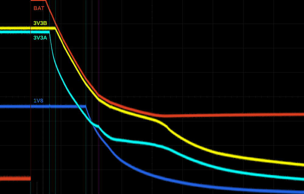
I've marked the PMIC sequencer "strobes" with vertical dashed lines, partially cut away when irrelevant or visually interfering with the signal plots. Unless noted otherwise, the interval between strobes is 1 ms.

As I mentioned, in off-state SYS is tied to BAT, and when DC-powered they hover around 1V for some reason (they'll drop if you try to drain power from either, but once you stop they bounce back to 1V). All regulated supplies are off. Once the PMIC has detected a wakeup event, it connects SYS to the DC power supply, asserts the wakeup signal, and the sequencer powers up the "always-on" supplies:

  • strobe 15: LDO1 (rtc, vdds)
  • strobe 14: unused
The AM335x RTC asserts PW_EN and once debounced by the PMIC (~50 ms) the sequencer completes the power-on sequence:

  • strobe 1: DCDC1 (ddr)
  • strobe 2: LDO3 (1v8)
  • [5 ms delay]
  • strobe 3: LDO2 (3v3aux = power led)
  • strobe 4: LDO4 (3v3a, enables 3v3b)
  • strobe 5: DCDC2 (mpu), DCDC3 (core)
  • strobe 6: unused
  • strobe 7: unused
Meanwhile, since BATMON isn't connected to BAT, the PMIC doesn't really get what's going on there. It seems to attempt to charge it for a while, then gives up, and later BAT somehow manages to drop below 0V and stay there (behaviour is quite different if BATMON is connected to BAT, in which case it's pulsed a few times then drops to about 0.2V - 0.4V, apparently depending on system load).

When reentering off-state the PMIC shuts down the supplies in reverse order, with 1 ms between strobes 1 and 14. Strobe 7 is relevant this time because it marks when shutdown is initiated, and as a result SYS is disconnected from DC power and connects to BAT, which immediately shoots up to SYS level. Note however that 3v3b is not disabled at strobe 4 but stays slightly below SYS until long after the PMIC has completed shutdown. About 20 ms after it was supposed to, it finally begins to drop to zero while SYS, now unloaded and heavily supported by fat capacitors, begins its long and slow journey back towards the 1V.

For comparison, the same plot but now powered at 3.6V through BAT (using a variable power supply).
 

When BAT was powered up, SYS started tracking it once it reached 1V (hmm, sounds familiar), but the PMIC initially remains in off-state. The boot and shutdown are essentially the same, except SYS follows BAT continuously. As a result, once 3v3b is turned on, it remains on until power to BAT is cut.


Bottom line: if you want to run on battery power, this is a serious problem. You'll need to keep the PMIC in active-state, though you can minimize power by commanding the ethernet phy and hdmi framer to power themselves down, and then enter a deepsleep mode. Alternatively, you'd need to patch the hardware, or have an external circuit detect this situation (3v3b on while 1v8_adc off) and disconnect the battery to resolve it.

Andrew Bradford

unread,
Apr 29, 2015, 8:00:17 AM4/29/15
to Matthijs van Duin, beagl...@googlegroups.com
Hi Matthijs,
> lifetime; this leakage current may *damage the processor*.
>
> To illustrate all this, let's stare at some pretty pictures.
>
> Here's a capture of various power terminals during boot and shutdown
> while
> on DC power (click to zoom):
>
> <https://lh3.googleusercontent.com/-aWEH_7JAEbw/VUBn8aVmaoI/AAAAAAAAACE/5RFxipIqG_E/s1600/dc.png>
>
> I've marked the PMIC sequencer "strobes" with vertical dashed lines,
> partially cut away when irrelevant or visually interfering with the
> signal
> plots. Unless noted otherwise, the interval between strobes is 1 ms.
>
> As I mentioned, in off-state SYS is tied to BAT, and when DC-powered they
> hover around 1V for some reason (they'll drop if you try to drain power
> from either, but once you stop they bounce back to 1V). All regulated
> supplies are off. Once the PMIC has detected a wakeup event, it connects
> SYS to the DC power supply, asserts the wakeup signal, and the sequencer
> powers up the "always-on" supplies:
>
>
> - strobe 15: LDO1 (rtc, vdds)
> - strobe 14: unused
>
> The AM335x RTC asserts PW_EN and once debounced by the PMIC (~50 ms) the
> sequencer completes the power-on sequence:
>
>
> - strobe 1: DCDC1 (ddr)
> - strobe 2: LDO3 (1v8)
> - [5 ms delay]
> - strobe 3: LDO2 (3v3aux = power led)
> - strobe 4: LDO4 (3v3a, enables 3v3b)
> - strobe 5: DCDC2 (mpu), DCDC3 (core)
> - strobe 6: unused
> - strobe 7: unused
>
> Meanwhile, since BATMON isn't connected to BAT, the PMIC doesn't really
> get
> what's going on there. It seems to attempt to charge it for a while, then
> gives up, and later BAT somehow manages to drop below 0V and stay there
> (behaviour is quite different if BATMON is connected to BAT, in which
> case
> it's pulsed a few times then drops to about 0.2V - 0.4V, apparently
> depending on system load).
>
> When reentering off-state the PMIC shuts down the supplies in reverse
> order, with 1 ms between strobes 1 and 14. Strobe 7 is relevant this time
> because it marks when shutdown is initiated, and as a result SYS is
> disconnected from DC power and connects to BAT, which immediately shoots
> up
> to SYS level. Note however that 3v3b is *not* disabled at strobe 4 but
> stays slightly below SYS until long after the PMIC has completed
> shutdown.
> About 20 ms after it was supposed to, it finally begins to drop to zero
> while SYS, now unloaded and heavily supported by fat capacitors, begins
> its
> long and slow journey back towards the 1V.
>
> For comparison, the same plot but now powered at 3.6V through BAT (using
> a
> variable power supply).
>
> <https://lh3.googleusercontent.com/-igtCZe5bffg/VUBoUPZ5PKI/AAAAAAAAACM/xKL_ZMFQLso/s1600/bat.png>
>
> When BAT was powered up, SYS started tracking it once it reached 1V (hmm,
> sounds familiar), but the PMIC initially remains in off-state. The boot
> and
> shutdown are essentially the same, except SYS follows BAT continuously.
> As
> a result, once 3v3b is turned on, it remains on until power to BAT is
> cut.
>
>
> Bottom line: if you want to run on battery power, this is a serious
> problem. You'll need to keep the PMIC in active-state, though you can
> minimize power by commanding the ethernet phy and hdmi framer to power
> themselves down, and then enter a deepsleep mode. Alternatively, you'd
> need
> to patch the hardware, or have an external circuit detect this situation
> (3v3b on while 1v8_adc off) and disconnect the battery to resolve it.

You seem to be talking about the BBB, correct?
My initial work was on BBW back in 2012 (prior to BBB release).

It sounds like BBB has similar issues to BBW with running on battery but
that the issues are slightly different.

I'm not subscribed to this list any longer so please keep me in CC.
Thanks!
-Andrew

Matthijs van Duin

unread,
Apr 29, 2015, 11:30:14 AM4/29/15
to beagl...@googlegroups.com, matthij...@gmail.com, and...@bradfordembedded.com
On Wednesday, 29 April 2015 14:00:17 UTC+2, Andrew Bradford wrote:
You seem to be talking about the BBB, correct?

Correct, though it seems nearly all posts in this thread are referring to the BBB issue?

My initial work was on BBW back in 2012 (prior to BBB release).

It sounds like BBB has similar issues to BBW with running on battery but
that the issues are slightly different.

Well the similarity is that the regulator was being kept alive by leakage currents.

Your original question is actually very easy to answer: disabling 3V3A like you were is really really not allowed, and if leakage currents didn't keep it logic-high then the result would have been pulling nRESET low, game over.

Shutting down 3V3B is something you may be able to do if appropriate pad configuration is done (high-Z with receiver disabled, pull-up disabled, maybe pull-down enabled) depending a bit on the rest of the BBW schematic (I didn't study it in any detail), but that doesn't help you since it doesn't control 3V3EXP.

Bottom line: shutting down 3V3EXP on the BBW (other than in off-state or rtc-only sleep) is not going to happen without a hardware patch.

Matthijs van Duin

unread,
Apr 29, 2015, 1:07:05 PM4/29/15
to beagl...@googlegroups.com, and...@bradfordembedded.com, matthij...@gmail.com
On Wednesday, 29 April 2015 17:30:14 UTC+2, Matthijs van Duin wrote:
Your original question is actually very easy to answer

I posted a bit too hastily since I missed the second half of your original post.

If external hardware unconditionally drives or pulls up to 3V3EXP (in case of BBW) or 3V3B (in case of BBB) then at shutdown they are indeed applying power to IOs while the corresponding power domain has already been shut down, which is not allowed.

The BBB SRM (but not the BBW SRM) warns that "no pins are to be driven until after the sys_reset line goes high" but this statement isn't quite right since it only addresses boot and not shutdown (it should say "unless the sys_reset line is high") and pull-ups can also cause problems. Powering processor IO banks and attached hardware using separate supply lines is tricky to get right, all versions of beaglebones get it wrong, and it was wrong to dump responsibility for these issues onto CAPE developers by putting a statement like that in the SRM. The mandate given in the SRM is actually also violated by on-board peripherals of the BBB, for example by the UART level shifter.

I think the best solution would have been to have the regulator controlled by the PMIC_PGOOD output which also controls the power-on-reset input of the AM335x, but this too would need to be carefully analyzed to verify it doesn't cause issues.

Andrew Bradford

unread,
Apr 29, 2015, 2:18:51 PM4/29/15
to Matthijs van Duin, beagl...@googlegroups.com
If you take a BBW and cut the trace coming from U8 pin 5 (the LDO enable
line) and then wire U8 pin 5 to the PWR_LED net on page 2 of the
schematic, then the U8 LDO will shutdown correctly when on battery.
This fix was incorporated into BBB but apparently there are other
problems, too.

This is the only mod required to fix my original problem. No fancy
software needed.

Thanks,
Andrew

Matthijs van Duin

unread,
Apr 29, 2015, 4:12:00 PM4/29/15
to beagl...@googlegroups.com, matthij...@gmail.com, and...@bradfordembedded.com
On Wednesday, 29 April 2015 20:18:51 UTC+2, Andrew Bradford wrote:
If you take a BBW and cut the trace coming from U8 pin 5 (the LDO enable
line) and then wire U8 pin 5 to the PWR_LED net on page 2 of the
schematic, then the U8 LDO will shutdown correctly when on battery.

It will shut down.
It will however not shut down correctly, neither on battery nor on dc power.

So, the BBW has a slightly different power scheme, including a different variant of the PMIC which affects timing and use of strobes. For reference, the relevant changes are:
  • strobe 15: LDO1 (rtc)
and
  • strobe 1: DCDC1 (vdds, 1v8, ddr)
  • [5 ms delay]
  • strobe 2: LDO2 (power led)
  • strobe 3: LDO3 (3v3a, enables 3v3exp)
  • strobe 4: LDO4 (3v3b)
This works for boot, and it may have been okay for shutdown if strobe 3 directly controlled 3v3exp (some other TI PMICs have GPIOs in the power sequence for such purposes), though it'd still make me slightly nervous and I would have preferred a later strobe. Using 3v3b to enable 3v3exp would certainly have made more sense to me than 3v3a, and I think has a decent chance of working correctly.

In all cases it would be highly desirable to have the 3v3exp actively discharged when disabled like the PMIC LDOs do, but neither the BBW 3v3exp regulator nor the BBB 3v3b regulator does this. This means that even if they are shutdown before the 3v3a, their output rails may not discharge quickly enough and still end up getting (partially) discharged via processor IOs when the 3v3a shuts down. This is of course highly dependent on CAPE(s) present (if any), especially on the BBW.

Moving the enable to strobe 2 as you're suggesting however means that 3v3exp gets powered up a full milisecond before the 3v3a at boot. Any pins driven or strongly pulled high to 3v3exp by an external CAPE will heavily leak to the 3v3a through processor IOs. During shutdown the same thing happens again, plus some remaining discharge after the 3v3exp is disabled. This is not good for the long-term health of the processor.

This fix was incorporated into BBB but apparently there are other problems, too.

It was incorporated into BBB, and then undone in rev A6 for exactly the reason stated above. Unfortunately, instead of actually fixing the problem they reverted to using the 3v3a as enable-signal, even though the early posts in this thread show they knew about the problems this causes for battery-powered operation (though maybe they forgot).

To make matters worse, while the BBW needs a CAPE to trigger the problem since the 3v3exp is used exclusively for those, on the BBB the 3v3b and 3v3exp have been merged and the on-board peripherals powered by it already get the job done.

Matthijs

Andrew Bradford

unread,
Apr 30, 2015, 6:14:19 AM4/30/15
to Matthijs van Duin, beagl...@googlegroups.com
Hi Matthijs,

On 04/29/2015 04:12 PM, Matthijs van Duin wrote:
> On Wednesday, 29 April 2015 20:18:51 UTC+2, Andrew Bradford wrote:
>>
>> If you take a BBW and cut the trace coming from U8 pin 5 (the LDO enable
>> line) and then wire U8 pin 5 to the PWR_LED net on page 2 of the
>> schematic, then the U8 LDO will shutdown correctly when on battery.
>>
>
> It will shut down.
> It will however not shut down *correctly*, neither on battery nor on dc
> power.
>
> So, the BBW has a slightly different power scheme, including a different
> variant of the PMIC which affects timing and use of strobes. For reference,
> the relevant changes are:
>
> - strobe 15: LDO1 (rtc)
>
> and
>
> - strobe 1: DCDC1 (vdds, 1v8, ddr)
> - [5 ms delay]
> - strobe 2: LDO2 (power led)
> - strobe 3: LDO3 (3v3a, enables 3v3exp)
> - strobe 4: LDO4 (3v3b)
Thanks for the info!

I'm sure wonky power up and down timing is not helping the silicon.

For reference, I've not seen any failure of the am335x with this rework
when using a custom cape at my previous job. That's not saying there
isn't damage, just that I didn't see any. We had built up probably 200
BBW+cape systems. The custom cape used the 3V3EXP as an enable for
cape-side power converters, so that likely added a slight delay to the
cape actually starting and may mitigate some of the issue you're
pointing out.

Thanks,
Andrew

Matthijs van Duin

unread,
May 1, 2015, 1:01:06 PM5/1/15
to beagl...@googlegroups.com, and...@bradfordembedded.com, matthij...@gmail.com
On Thursday, 30 April 2015 12:14:19 UTC+2, Andrew Bradford wrote:
For reference, I've not seen any failure of the am335x with this rework
when using a custom cape at my previous job.  That's not saying there
isn't damage, just that I didn't see any.

I'm also not sure how easily the am335x would get damaged in this way... it'll be very much dependent on the external hardware anyhow. This is nicely illustrated by what I encountered in my continued investigation of the leakage caused by BBB on-board hardware:


I've captured the shutdown sequence on DC versus BAT power in more detail by zooming in, omitting the 5V rails, and including the 3V3A. This is with no external hardware connected to the BBB other than the power supply and measurement probes:


Since location of jumps/bends in the signals made me suspicious about the location of some strobes, I also measured LDOs 1 and 2 (not included here to avoid clutter). It turned out strobe 15 follows strobe 1 on shutdown, in contradiction of figure 5 of the TPS datasheet. Given the bend in 3V3A around strobe 15 it also seems that some leakage from one of the LDO1 supplies (vrtc, vio, vdds) to 3V3A is also happening? That would be rather weird and unexpected (not to mention highly undesirable), so maybe I'm misreading this or it's just a coincidence.

In the BAT-supply case, the current measured through BAT after shutdown is around 35 mA (somewhat dependent on temperature). I've analyzed the schematic and it appears there's no specific culprit: there are many IO lines with pull-ups to 3v3b:
  • 2× 4.75k for am335x boot mode (EMU0, EMU1)
  • 11× 10k for eMMC
  • 7× 10k for SD card
  • 1× 10k for HDMI irq
  • 4× 1.5k for ethernet (MDIO and phy mode select)
Since the total leakage is not huge and diffusely spread across dozens of processor IOs, and afaict no absolute maximum ratings are violated, it seems intuitively unlikely the cpu will get damaged this way. This will probably then also be true of the brief leakage currents occurring during boot and shutdown on DC power. (Not that I'm 100% sure about either)

Of course 35 mA @ 3.6V = 126 mW of power consumption is pretty bad, so even if the processor doesn't get damaged it seems to me that people who run into this problem and are unable or unwilling to patch it in hardware should focus on deepsleep modes (which keep the PMIC in active-state) instead. Optimizing these will be hard work though.


One thing one should however definitely never do, is leave a serial cable attached to a BAT-powered BBB whose 3v3b is stuck high. The uart buffer U15 is powered by 3v3b and directly drives the cpu UART0_RXD pin (even though ironically its intended purpose was to isolate the uart pins when the cpu is powered down). It has a pull-down on the associated input, but if you connect a serial cable it will be driven high instead. Here's the result:


Lots of thoughts going on staring at those pictures: Much steeper slopes in the DC power case already indicate much higher currents. On battery power the 3V3A ends up a full volt higher than before, whoa, and wtf is that sudden surge on the 3V3A shortly after shutdown? Red warning lights start flashing in my head. Uhh, 3V3A is exceeding the 1.8V supplies by more than 2V there, a situation the am335x datasheet repeatedly and emphatically warns should be avoided under all circumstances.

Current through BAT (right before I quickly turned the PSU off) read 80 mA, 45 mA higher than before. Wait, does that mean this 45 mA flows through a single pin of the cpu? What's the specified latch-up limit anyway? Looks it up... 45 mA. Uh oh...


So here we have a case where the situation was changed from "hmm, annoying power consumption" to "DANGER WILL ROBINSON, DANGER" by something as seemingly innocuous as attaching a serial cable to the console port.

In the DC-powered case everything is happening rather quickly and I have no idea how to estimate how big the risks are to the CPU, or whether cumulative damage may occur. At first glance it seems to avoid overvoltage stresses in this case (which I know are cumulative), and overcurrent situations are afaik mainly thermal in nature hence dependent on their duration. But even 1 ms may very well be an epic age to a processor like the am335x, I just have no idea.

In any case, the leakage currents occurring due to enabling 3v3b 1ms before 3v3a were sufficient motivation for a patch in BBB rev A6, so presumably they are not something to be ignored.


When CAPEs are attached, everything will depend on what exactly they are doing.


As far as hardware patches go, probably the most elegant solution would be to have the 3v3b (3v3exp in case of BBW) regulator actively track the 3v3a voltage rather than using it as enable-input. This avoids a problematic voltage difference under all circumstances, and all nets needed for this are already available at the site of the regulator, which simplifies things. (If the gods are in a very generous mood, perhaps there's even some pin-compatible chip that does it... yeah right, just dreaming here.)

It would also allow the 3v3b to take advantage of the better calibration the 3v3a voltage seems to have, and the ability to adjust it at runtime for fine-tuning. In my pictures the 3v3b is evidently set slightly too high, and as a result gets poorly regulated on 3.6V supply.

The next best thing would be using a proper enable-signal occurring somewhere in the power sequence after the 3V3A but no later than PMIC_PGOOD (= am335x PORz). The PGOOD signal itself still seems like the best choice, unless some CAPE ends up unintentially pulling down SYSBOOT pins as a result (though iirc the cpu samples sysboot some time after PORz goes high, but this would need to be verified).

Using an enable-signal asserted before and/or deasserted after the 3V3A (such as LDO2 feeding the power led) is suboptimal but may work adequately. I'd still especially try to avoid strongly driving cpu pins during boot or shutdown (as happens on the BBB when console rxd is high), since that would leave me worried about the cpu's long-term health.

If one plans some ugly hack to make working enable-signal out of the 3V3A itself using voltage dividers or such, keep in mind it will still shut off later than desirable (3V3A only needs to drop 0.3V below 3V3B for leakage to start occurring) and the regulator isn't guaranteed to shut off unless EN drops below:
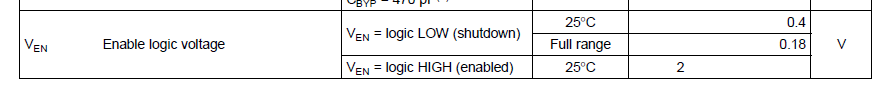
  • 0.50 V (BBW regulator)
  • 0.40 V (BBB regulator, 25 ͏°C)
  • 0.18 V (BBB regulator, whole temperature range)

Anyhow, I'm inclined to declare this issue "fully clarified" now, or at least I've done all investigation I'm probably going to. To those suffering from this issue I'd advise carefully reading this thread (or at least this branch thereof) and weighing the pros and cons of the various workarounds suggested, since the most suitable one will depend the individual situation.

Good luck to everyone!

Matthijs

Matthijs van Duin

unread,
May 1, 2015, 7:35:04 PM5/1/15
to beagl...@googlegroups.com, matthij...@gmail.com, and...@bradfordembedded.com
On Friday, 1 May 2015 19:01:06 UTC+2, Matthijs van Duin wrote:
I've captured the shutdown sequence on DC versus BAT power in more detail
 
Just a quick clarification to avoid confusion:

Unlike the scope images in my original post, these were captured with BATMON connected to BAT even in the DC-powered case. As I mentioned in my original post this somewhat changes the behaviour of the TPS65217, and in particular prevents BAT from ever dropping below 0V, which would be out of view in these images.

The vertical range of these images is 0V...4V, grid lines are spaced 0.5V and 5ms, minor ticks 0.125V and 1ms.

The images in my original post have vertical range -1V...6V, grid lines spaced 1V and 20ms, minor ticks 0.25V and 4ms. They were taken with serial cable attached.

Matthijs

Max

unread,
May 19, 2015, 4:41:38 PM5/19/15
to beagl...@googlegroups.com, matthij...@gmail.com
Matthijs,
Did you try any change in the EN pin of U4 (enable signal of 3V3B)?
I'm about to try SYS_RESETn (PMIC_PGOOD after U16), but I'm concerned about the 20ms turn on delay (plus 10ms due to the RC).
The other option is to go back to use 3V3AUX, and add a 1k load resistor to reduce the discharge time.
Thanks,
Max

Matthijs van Duin

unread,
May 19, 2015, 10:52:06 PM5/19/15
to Max, beagl...@googlegroups.com
On 19 May 2015 at 22:41, Max <msonn...@gmail.com> wrote:
Did you try any change in the EN pin of U4 (enable signal of 3V3B)?

No, we replaced U4 by this state-of-the-art voltage-tracking regulator:


It can't supply as much current as the original, but our needs are modest enough.

 
I'm about to try SYS_RESETn (PMIC_PGOOD after U16), but I'm concerned about the 20ms turn on delay (plus 10ms due to the RC).
The other option is to go back to use 3V3AUX, and add a 1k load resistor to reduce the discharge time.

I would advise against both of these choices: Only PORz guarantees that the AM335x IOs will be high-Z, SYS_RESETn is deasserted considerably later during power-on. Using it would also case 3v3b to be power-cycled during warm reset, which may have pros and cons but in any case if I'm reading the TRM right it is asserted too early in this case and therefore there's a risk the AM335x ends up driving into unpowered external peripherals.

Any reason why you're not considering PMIC_PGOOD itself? In general I'd restrict to PMIC signals that transition somewhere between strobe 4 and PGOOD, which makes PGOOD itself basically the only signal that qualifies.

If you do use LDO2 (3v3aux) for whatever reason, try to avoid having any signal to the AM335x being driven high from the 3v3b during boot. In particular, avoid having a console cable connected at boot (at least during production use) given the stress this would put on the UART0_RXD pin. It would then also be a good idea to reprogram LDO2 to strobe 7 as soon as possible during early boot (preferably in the SPL).

A load resistor on 3v3b may be a good idea anyway since it lacks the active discharging that the PMIC LDOs have.

Maximiliano O. Sonnaillon

unread,
May 20, 2015, 7:55:44 AM5/20/15
to Matthijs van Duin, beagl...@googlegroups.com
Thanks for your response.
I see your point about not using SYS_RESETn signal... it can be driven low by the processor.
I was considering that one because it's a 3.3V logic signal. PGOOD is a 1.8V signal and the EN pin of U4 has a minimum of 2V to consider it high.
Inline image 1
I will probably have to add an extra buffer to have PGOOD in 3.3V level to drive the U4-1 and also use it to enable a regulator in my cape (it's actually more like a motherboard). Maybe in the next rev of my custom BBB I will make U16 a dual gate.

The reason I'm investigating these PMIC details is that I'm using a custom BBB for am industrial application, and we had a couple boards (BBB and custom one) fail. I recently found warnings in new BBBs to avoid "damage in the board". https://groups.google.com/forum/#!topic/beaglebone/CKuTbHepHYE

Matthijs van Duin

unread,
May 22, 2015, 4:05:51 PM5/22/15
to Maximiliano O. Sonnaillon, beagl...@googlegroups.com
On 20 May 2015 at 13:55, Maximiliano O. Sonnaillon <msonn...@gmail.com> wrote:
I was considering that one because it's a 3.3V logic signal. PGOOD is a 1.8V signal and the EN pin of U4 has a minimum of 2V to consider it high.

Ick, I completely overlooked that. So it seems there's no single simple solution...

my cape (it's actually more like a motherboard).

Same here, that's actually why we can get away with removing U4 and tying 3v3a and 3v3b together: power-hungry stuff on our board is supplied separately anyway. Perhaps the same could work in your case?

LDO4 is rated for 400 mA, about half of which can be consumed by eMMC + ethernet, which leaves about 200 mA for basically just communication between the BBB and the cape. This is really a quick back-of-envelope estimate which will need more careful analysis of course.

Having a unified 3.3V supply on the BBB really does make things a lot easier. If your cape uses the same supply (or one that tracks its voltage) for its IO drivers towards the BBB, the problem of current flowing through protection diodes due to uneven 3.3V supplies during power-up/down should be solved entirely. You can ignore PGOOD and reset signals in that case.

The reason I'm investigating these PMIC details is that I'm using a custom BBB for am industrial application, and we had a couple boards (BBB and custom one) fail. I recently found warnings in new BBBs to avoid "damage in the board".https://groups.google.com/forum/#!topic/beaglebone/CKuTbHepHYE

I'm investigating the PMIC details basically to avoid similar things happening to us ;-)  Especially since there's no way in hell our end-users are going to perform clean shutdowns.

The quirky PMIC and the power supply structure of the BBB are both headache-inducing material.

When I find a moment I'll be sure to post some observations on shutdown behaviour in that thread.

Matthijs van Duin

unread,
May 24, 2015, 8:47:05 PM5/24/15
to Maximiliano O. Sonnaillon, beagl...@googlegroups.com
On 20 May 2015 at 13:55, Maximiliano O. Sonnaillon <msonn...@gmail.com> wrote:
I will probably have to add an extra buffer to have PGOOD in 3.3V level

Heh, it's a pity U3 is an inverter rather than a buffer... it's currently not actually used (hardware reset is not enabled in eMMC), it's located at the top of the PCB (where you can also find PGOOD) while its output is available via R162 on the bottom of the PCB (where you'd need the enable signal for the regulator), and since its existing input and output connect to pins which are high-Z/don't-care by default you wouldn't even need to disconnect those.

But there's no useful inverted signal available to use as enable afaict...
Reply all
Reply to author
Forward
0 new messages