Smoked ssr
447 views
Skip to first unread message

adam paul
Nov 12, 2015, 2:33:42 PM11/12/15
to 3D Printer Tips, Tricks and Reviews
I set my big bot to preheat last night, and went up to do some chores, 10ish minutes later I think to myself "hmm, what's that funky smell", which in my house is usually more toddler related. I go and check the printer with the hbp saying 97/70 and the led indicating further heating. Shutting down the preheat using the menu did not affect the heating. My hbp is 12v being switched by the 24v mightyboard. The ssr, sourced from Amazon, is fauxtek I'm sure. Any suggestions on a good ssr for dc-dc? I am hesitant to use a mains powered heater for my moving z bed, but I could be convinced with proper strain relief, maybe.

Jetguy
Nov 12, 2015, 2:37:08 PM11/12/15
to 3D Printer Tips, Tricks and Reviews
There are no good DC DC SSRs. It needs to be a FET. I went through this and blew one sky high.
I can build you one and mail it to you.
I can build you one and mail it to you.
adam paul
Nov 12, 2015, 4:32:22 PM11/12/15
to 3D Printer Tips, Tricks and Reviews
Thanks, I'll pm you when I'm not at on mobile.
adam paul
Nov 17, 2015, 1:48:54 AM11/17/15
to 3D Printer Tips, Tricks and Reviews
Thought I would post a post mortem....
looks like the magic smoke decided to quit and vacate. I think I might switch to 24V, should make the smoke less angry.

Chris P
Nov 17, 2015, 8:00:53 AM11/17/15
to 3D Printer Tips, Tricks and Reviews
Impressive. Did you have any heat sink attached to the bottom plate? I've played with a few and they get scary warm unless they're attached to a heat sink. Wondering if that contributed to the magic smoke escaping.
Jetguy
Nov 17, 2015, 8:12:34 AM11/17/15
to 3D Printer Tips, Tricks and Reviews
I had a whole thread on the exact same failure.
On so many levels, just junk.
The actual transistor is a bipolar NOT a FET.
It's also NOT on this planet rated for the nameplate current rating.
Heatsink or not- NOBODY should use the cheap DC to DC SSRs for more than 1-2A and even that's a stretch......
On so many levels, just junk.
The actual transistor is a bipolar NOT a FET.
It's also NOT on this planet rated for the nameplate current rating.
Heatsink or not- NOBODY should use the cheap DC to DC SSRs for more than 1-2A and even that's a stretch......
Chris P
Nov 17, 2015, 9:14:07 AM11/17/15
to 3D Printer Tips, Tricks and Reviews
I had a whole thread on the exact same failure.
Do you have a link? I'd like some light lunchtime reading :-)
Jetguy
Nov 17, 2015, 9:30:52 AM11/17/15
to 3D Printer Tips, Tricks and Reviews
Fair enough so the story begins here and continues on through that thread https://groups.google.com/d/msg/3dprintertipstricksreviews/rz6fpdRMus8/bhWncvhRqHMJ
OK, so for S's and G's i opened up the SSR.
Output device is an NEC C2751 http://html.alldatasheet.net/html-pdf/438982/ISC/2SC2751/54/1/2SC2751.html
It's rated at 15A and a peak of 30A. The fact it's an NPN and not a MOSFET as i had predicted is interesting (maybe only to me).
It is blown and is currently conducting 0.6 Ohms.
So, word to the wise, This Fotek (I'm no calling these FU-tek because they must think this is OK) is NOT rated for 25A on the face.
SSR-25 DD
However, searching the web, I cannot find any reference to this SSR on any Fotek site. They only make DC SSR of 5 and 10 Amp rating????
Just saying, double failure today.
SSR is junk at best and potentially counterfeit and even if not, the rating is not to be trusted given the "find out what's inside test".
On Tuesday, November 17, 2015 at 9:14:07 AM UTC-5, Chris P wrote:
Jetguy
Nov 17, 2015, 9:42:24 AM11/17/15
to 3D Printer Tips, Tricks and Reviews
Relevant back to Adam who I need to send this circuit. FYI, I have run this for several months and it has proven to be a working solution. We can have debates if it's "right" or passes even basic EE protocols. What I did is parallel 2 matching FETS from the below parts bin (I think I used IRFZ44) bolted and insulated on an old PC power supply internal heatsink using thermal pads and insulated washers on the tab screws. I then connected heavy gauge wire #12 to a source and drain pins to a high current rated pair of insulated screw terminals.
The tiny SSR removed from previous mightyboards safety circuits (I have a little baggie of these removed ones over the years) makes a perfect inverting gate driver.
Assumptions!!!!!
ONLY works on a 12V system. I'm feeding roughly 11V gate drive to FULLY saturate the FETS into the lowest RDS on resistance state.
It's using both of the screw terminals on the HBP output from the mainboard and is polarity sensitive.
But it serves the function since the mightyboard switches low side, the LED in the optocoupler portion of the SSR only lights when grounded. When that happens, the SSR enables the 12V to the gate of the paralleled FETs thus turning them on. A 5K pulldown ensures when the gate drive is off, we pull the gate back down into the off state.
Again, this is extremely polarity sensitive. It has 1 purpose in life, to invert the mightyboard output and drive the paralleled FETS to full on to reduce any heating.
So i dug into the parts drawer and here's what I got:
IRFZ44 - 35A continuous
FQP50N06L - 35A continuous
From mightyboards- removed AQV252G SSR (trick little opto-isolator and FET module rated at 2.5A max)
So the opto-isolator is ideal to invert the low side switched output of our mightyboards. Simply use the correct value resistor in series and all you are doing is lighting an LED inside the opto.
The output then drives the gate of the larger main current FET and you now have an opto isolated switch capable of some serious current without blowing sky high.
Jetguy
Nov 17, 2015, 10:39:02 AM11/17/15
to 3D Printer Tips, Tricks and Reviews
Disclaimer, I just did the worlds worst schematic in MS paint. This is horrible but gives you an idea.
There may be mistakes, I'm going off of what I did several months ago and stuck under heatshrink after it worked.
This was a total parts bin build made from scrap removed parts from PSU and failed mightyboards.
I did not add protection diodes since this is a non-inductive load and the IRFZ44s have some internal protection.


Rich Webb
Nov 17, 2015, 10:46:02 AM11/17/15
to 3D Printer Tips, Tricks and Reviews
OMFG. Painful but nice. Pick up a copy of KiCad, even if you only use it once a year. It's FOSS and has been picked up by CERN, so not a toy. RC2 of the new stable release was out a few days ago.
Jetguy
Nov 17, 2015, 10:48:02 AM11/17/15
to 3dprintertips...@googlegroups.com
DARN Immediate mistake. See, I warned you.
The pulldown as drawn is a massive failure on my part.
The truth is, I soldered the resistors right on top of the FETS
Fixed diagram

On Tuesday, November 17, 2015 at 10:39:02 AM UTC-5, Jetguy wrote:
Jetguy
Nov 17, 2015, 10:49:17 AM11/17/15
to 3D Printer Tips, Tricks and Reviews
Great suggestion on KiCad, but not on a personal laptop at the moment where I could install software.
Hence- MS Paint.
Chris P
Nov 17, 2015, 10:49:49 AM11/17/15
to 3D Printer Tips, Tricks and Reviews
@Jetguy: So the SSR failed immediately, or after some number of hours of runtime?
Jetguy
Nov 17, 2015, 11:05:19 AM11/17/15
to 3D Printer Tips, Tricks and Reviews
I my case immediately but would have failed sooner rather than later.
I had a situation where even my own personal checking failed me. I had a few 300mm AKA 12inch heater pads in the parts pile. NONE had a label.
As I remembered it, some where 12V and I thought I had a 24V version. So, I measured them using a multimeter. Typical 12V is 1-1.5 Ohms for a bed of that size.
I know I double and triple measured it and got a high value for a 24V bed. I marked with a sharpie 24V bed.
I connected it to 24V and blamo- loud pop and heating of the bed stuck on.
Amazingly, the Meanwell 24V 14A rated PSU took this insane abuse without tripping or exploding!!!!
It PEGGED my 20A rated meter in current mode and that PSU did it's job for SEVERAL minutes of serious abuse without a wimper.
Again, AT best, the circuit inside this 25A "rated" SSR module from FOTEK was actually rated for 15A sustained in a best case scenario (massive heatsink, fan cooling, etc)
Knowing these are using BJTs, knowing they are totally bogus rated, and knowing they fail shorted ON, nobody on the planet should use the SRRs for heated beds (the Foteks and anything like them)
This only applies to the DC to DC ones. I have and am using the AC versions and they work fine.
Jetguy
Nov 17, 2015, 11:14:25 AM11/17/15
to 3D Printer Tips, Tricks and Reviews
Back to the circuit.
Again, you might say why are you using an SSR in that circuit?
The big reason is a I needed a simple way to invert the mightyboard output since it is ground switched.
I had the parts on hand after removing them from miightyboards and they were sitting in the parts bin.
IN theory, even if the circuit fails, the mightyboard is not damaged or modified.
It's not perfect, it's not the best answer. However, it was a fix and worked good enough for me to share.
And, I'm sending Adam a completed and proven tested (my own personal one) since I switched to 120V AC bed and SSR.
I can build myself another one for when I use that bed in another bot.
You could build the circuit a number of ways for sure, but this one fails safe if the mightyboard is unpowered or not connected. The FETs have no reason to turn on.
It takes a proper input and polarity into the SSR to even make the heater turn on.
Yes, like any circuit, the FETs could fail. It's not ESD protected by much other than the pulldown at the FETs.
It was a low parts count scrap bin build.
adam paul
Nov 17, 2015, 5:56:12 PM11/17/15
to 3D Printer Tips, Tricks and Reviews
Thanks JG! Next time you come to bay area, I'll cook you dinner.
@Chris, my ssr failed after 100 hours or so. It may have been the first time I set it to ABS temps. I'm not sure where the 110 came from in the preheat settings, I mostly print PETG at 70 on that printer and have not had the ABS out in a while. It was on the standard ssr heatsink.
Chris P
Nov 17, 2015, 8:16:30 PM11/17/15
to 3D Printer Tips, Tricks and Reviews
Thanks for the info. I have one under test now running about 400W through it at 24vdc at whatever repetier's pwm frequency is (30 Hz?) We're a couple days in and no "boom" yet :-) I do have it mounted to a massive 1.8" AL plate to act as a heat sink, with CPU thermal paste to aid the heat transfer. The base of the SSR is warm but comfortable to touch.
I'm no EE, but it seems like most SSR failures can be traced back to getting too hot, no? Besides Jetguy trying to feed infinity amps through his :P
Chris
Jetguy
Nov 17, 2015, 8:36:26 PM11/17/15
to 3D Printer Tips, Tricks and Reviews
Correct, the problem is thermal runaway. https://www.youtube.com/watch?v=YNoZd8FvLLg
Also, you can have a huge heatsink, and if the cheaply made device has high internal thermal resistance to the case- thermal runaway and failure.
Simply put, BJT is not the right way to run a heated bed.
The thing is, that the root can be thermal, but again, there are simply circumstances that are out of a users hand. You think it's heatsinked and it is, but the actual junction die to everything else is the thermal limit.

Dan Newman
Nov 17, 2015, 8:49:47 PM11/17/15
to 3dprintertips...@googlegroups.com
On 17/11/2015 5:36 PM, Jetguy wrote:
> Correct, the problem is thermal runaway.
> https://www.youtube.com/watch?v=YNoZd8FvLLg
>
> Also, you can have a huge heatsink, and if the cheaply made device has high
> internal thermal resistance to the case- thermal runaway and failure.
> Simply put, BJT is not the right way to run a heated bed.
>
> The thing is, that the root can be thermal, but again, there are simply
> circumstances that are out of a users hand. You think it's heatsinked and
> it is, but the actual junction die to everything else is the thermal limit.
FWIW, I've used Crydom SSRs in the past. Well made, reputable brand. Never had
> Correct, the problem is thermal runaway.
> https://www.youtube.com/watch?v=YNoZd8FvLLg
>
> Also, you can have a huge heatsink, and if the cheaply made device has high
> internal thermal resistance to the case- thermal runaway and failure.
> Simply put, BJT is not the right way to run a heated bed.
>
> The thing is, that the root can be thermal, but again, there are simply
> circumstances that are out of a users hand. You think it's heatsinked and
> it is, but the actual junction die to everything else is the thermal limit.
any problem with them when used properly. OTOH, I've seen pretty suspect SSRs
which people have bought from Joe Random suppliers on eBay and Amazon.
Dan
Jetguy
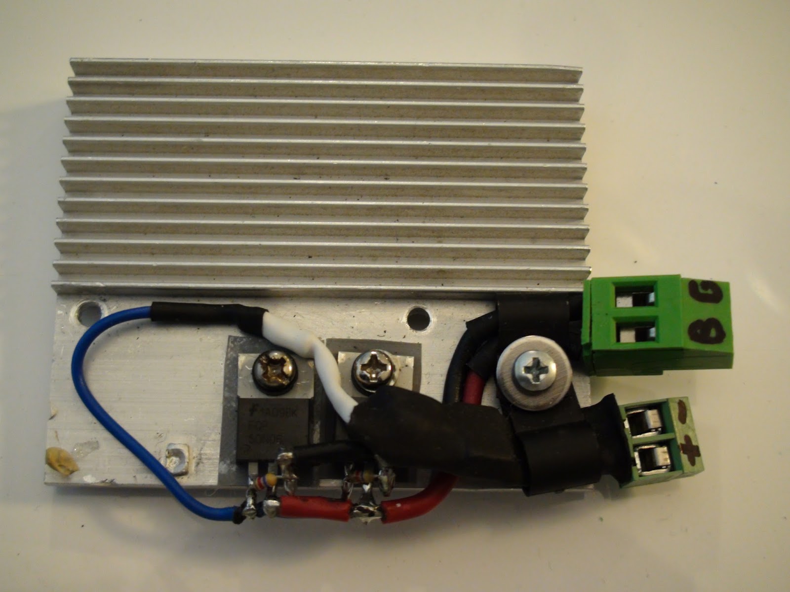
Nov 18, 2015, 7:54:28 AM11/18/15
to 3D Printer Tips, Tricks and Reviews
Man, I just seem to be full of screw-ups. Reversed the FET Source and Drain connections.
Here is the actual unit
The small screw terminals go to the HBP output at the mainboard
The large high current beasts go to the PSU negative (labeled "G") and then the terminal labeled "B" goes to the return wire of the BED while the other bed wire goes to the +12v PSU

Jetguy
Nov 18, 2015, 8:15:34 AM11/18/15
to 3D Printer Tips, Tricks and Reviews
Correct diagram

adam paul
Nov 19, 2015, 1:36:57 AM11/19/15
to 3D Printer Tips, Tricks and Reviews
I was really going over the drawings tonight, then went back to re read your posts. The drawing clearly is labeled 12v on both the mightyboard and the hbp sides of the FETs, and your post confirms that. I have a 24v mightyboard switching a 12v hbp. Are the FETs not 24v tolerant or the ssr?
While I understand on my bike why I need 6 FETs for 12 amps, 10 for 25 amps...... And coming soon in the mail 24 FET for 110 amps at up to 132v, we can get away with 2 for 20 amp.
Also a 10kW/h motor coming from Croatia, I might want to race your little lawnmower

Joseph Chiu (Toybuilder)
Nov 19, 2015, 4:53:47 AM11/19/15
to 3D Printer Tips, Tricks and Reviews
The key thing to remember is that many of these devices have a rated current limit AND total power dissipation limit AND thermal limit.
So, yeah, sufficient heat sinking is often needed.
--
You received this message because you are subscribed to the Google Groups "3D Printer Tips, Tricks and Reviews" group.
To unsubscribe from this group and stop receiving emails from it, send an email to 3dprintertipstricks...@googlegroups.com.
To post to this group, send email to 3dprintertips...@googlegroups.com.
Jetguy
Nov 19, 2015, 8:07:22 AM11/19/15
to 3D Printer Tips, Tricks and Reviews
OK, so a minor wiring change.
Again, let's go over the challenges we face.
#1 the mightybord output does not switch a positive signal, it is an FET that grounds. That cannot "drive" any other circuit as it "sinks" current, not sources it.
#2 in order to ensure the FET is fully on, we need a voltage greater than 5V signals produced by the atmega 5V processor outputs. That is why your other controller also uses more FETs, they are not being driven to a full on and lowest resistance state to prevent heating. Paralleling them lowers the total effective on resistance and "shares" the load across multiple devices.
#3 there is an upper limit we can drive the gate voltage with and that's 20V not the 24V. Gate drive voltage as drawn is sourced from the HBP output terminals as drawn. I assumed you used 1 power supply voltage of 12V and now you have a mixed system of 12V and 24V.
What I didn't want to do was modify the mighty board. For a number of reasons, that's not easy and also just not the safest option.
It still can work, we just need to slightly adapt the wiring.
First, BOTH the 12V and 24 V PSUs need the negative output terminals tied together with a single wire. I realize you probably have both connected to ground or earth on the mains inputs but the output negative only must also be bonded between the 2 supplies.
Then the only wire going from the new FET module to the main board will be the smaller screw terminal negative goes to the switched HBP output negative. The smaller screw terminal positive now would run a short wire back to the 12V power supply + terminal. The HBP also has 1 wire that goes to the positive PSU 12V terminal and the other wire from the bed goes to the "B" terminal on the FET. The "G" terminal on the FET is connected to the 12V negative PSU OUTPUT.
Again, the summary of changes is 2 wires.
The 12v and 24V PSUs get a wire added connecting the negatives.
The + labeled small screw terminal no longer connects to the mighty board and instead, connects to the 12V + PSU output.
I'll make a drawing.

WZ9V
Dec 8, 2015, 9:00:26 PM12/8/15
to 3D Printer Tips, Tricks and Reviews
These might be an option if you don't want to build something.
Jetguy
Dec 8, 2015, 10:56:24 PM12/8/15
to 3D Printer Tips, Tricks and Reviews
No, the common ground input prevents proper operation.
It keeps going back to the fact of the mightyboard and most every other board on the planet switching ground outputs not high side.
Sure, you could always mod the mightyboard and use the direct 5V output gate of the 1280/2560 but that's hacky.
The whole point is a totally external circuit that translates a switched ground output into a gate drive of a properly rated FET.
WZ9V
Dec 9, 2015, 8:15:47 AM12/9/15
to 3D Printer Tips, Tricks and Reviews
Why not just have the FET drive a voltage divider and then use the voltage from that to drive the CTRL pin or gate n the case of the external FET. It's essentially just like the old open collector TTL logic. When the FET is off the line will be pulled high by the resistor when on it will will be pulled low by the FET. The voltage divider just gives you the range you want, since it's a 12V or 24V on the high side of the connector.
Jetguy
Dec 9, 2015, 8:26:48 AM12/9/15
to 3D Printer Tips, Tricks and Reviews
That inverts the on/off state.
Jetguy
Dec 9, 2015, 8:34:01 AM12/9/15
to 3D Printer Tips, Tricks and Reviews
Point being, generally we hope for 3 things
#1 not modifying the board
#2 not using anything but stock firmware
#3 using an external module that simply wires to the existing output.
Few devices are made to handle this.
This is one of the few devices made that meets those specifications http://reprap.me/power-expander.html
The basic circuit isn't all that different from what I've created.
I described it earlier- that is a 6 wire device.
You have main power in, high power ouput, and the incoming control signal.
My circuit was reduced since technically, the input signal power is the same as the main power input.
Electrically, the circuit is the same- the connections look different, but at the schematic level- circuit is identical.
Input is opto isolated and because all you are doing is lighting an LED in a photo pair- it can use the switched ground output at the mainboard.
The gate drive voltage to the FET is still coming from the incoming power source switched by the optocoupler.
WZ9V
Dec 9, 2015, 10:50:30 AM12/9/15
to 3D Printer Tips, Tricks and Reviews
True but in Smoothie at least that's a simple config setting on that pin.
Your opto-isolator seems redundant since it your driving the gate off of the input power supply. Wouldn't it be better for that to be powered from the output side PS which would totally isolate the output side from the input side which is the point of the opto-isolator.
Your opto-isolator seems redundant since it your driving the gate off of the input power supply. Wouldn't it be better for that to be powered from the output side PS which would totally isolate the output side from the input side which is the point of the opto-isolator.
On Wednesday, December 9, 2015 at 8:26:48 AM UTC-5, Jetguy wrote:
Jetguy
Dec 9, 2015, 10:58:34 AM12/9/15
to 3D Printer Tips, Tricks and Reviews
No, the point of the isolator is to invert a current sinking output into a voltage sourcing output.
How you get from A-B doesn't matter.
The rules are quite simple.
Yes, you can use 6 terminals and go "through" the device.
Or you can smartly look at the bigger schematic and see it's ALL the same source.
Jetguy
Dec 9, 2015, 11:06:03 AM12/9/15
to 3D Printer Tips, Tricks and Reviews
Again, let's look at rules AKA requirements.
#1 not mod the mainboard
#2 not mod the firmware
#3 Not mention Smoothie again
#4 device should be simple and low cost
#5 FET input must be fully turned on. typical FET rating is 10V gate. Also must make a note of typical 19-20V MAX gate voltage.
So depending on the setup, we need to look at the bigger picture.
In this case, the mightyboard was 24V power.
The heater was 12V high amperage
You can gate drive directly from the 12V source but NOT from a 24V source as that exceeds the 19-20V max gate voltage.
You could use a regulator or voltage divider but that's more parts/added complexity/room for failure to lead to a failed and stuck on FET
In my machine, I was running a SINGLE 12V supply.
That mean no matter where I sourced the 12V from, it ALL was 12V from the same place.
LESS terminals in the HIGH CURRENT side is HIGHLY recommended.
There is ZERO need to pass HIGH CURRENT 12V positive into the FET board and back out another connector to the bed. All I needed was a VOLTAGE source of 12V with minimal current.
My device has only 4 screw terminals- 2 high current and 2 low current.

Ryan Carlyle
Dec 9, 2015, 11:31:39 AM12/9/15
to 3D Printer Tips, Tricks and Reviews
Another thing to consider is whether non-firmware behavior (bootloaders, pull-downs, etc) will cause an inverted heater to go ON at startup because the non-firmware design assumed non-inverted heater logic. This can be a fairly big problem when you invert heater logic if the firmware hangs at startup or what have you.
In general, making the controller actively assert the "heater off" state is terrible design.

JolietDelta
Dec 9, 2015, 11:32:49 PM12/9/15
to 3D Printer Tips, Tricks and Reviews
Good point Ryan. One of the older revisions of Repetier came to a sudden halt every now and then. Usually after some hours printing time. In one of those cases one of my 24V HB transformed a already finishec print into a nice
PLA meatball. From this time on none of my printers ran without a thermal fuse on the printhead and on the HB.
Additionally I slightly modified the FW. The HB is driven over two power FETs. Repetier now uses two pins. One for the PWM and one for sensing the actual PWM behind the FETs. Behind the FETs is a simple voltage devider, an optocoupler and a Schmidt-Trigger for generating a clean signal. The watchdog loop in Repetier now compares the falling edges of the signals on these two pins, PWM out and sense in. If the hardware fails, and - in theory - it shouldn't make any difference if an external SSR blows up or the onboard MOSFET, the watchdog routine detects a daviation between outgoing PWM and the incoming sensing signal. This also prevents damage if one manages to short the HB.
Every modern ceramic hob has this kind of safety circuit. At least in the EU it is mandatory for getting CE certified.
~Jens
Ryan Carlyle
Dec 10, 2015, 5:04:12 PM12/10/15
to 3D Printer Tips, Tricks and Reviews
That's a cool approach.
Reply all
Reply to author
Forward
0 new messages