Building a Prusa i3 now....

2,319 views
Skip to first unread message

TheMakerGuy

unread,
May 19, 2013, 8:29:20 PM5/19/13
to 3dprintertips...@googlegroups.com
I've kind of had enough of this Rostock Max. After I adjusted the Delta_Radius I got a much better print from it. Then I tried to do better and could not. I took a look around the bot and noticed black dust below the idlers and belts. Guess what? The metal pulleys have been chewing through my belts. The little gaps in the belts are a bit transparent now. I only did about 15 prints so far. It works out that SeeMeCnc switched to plastic pulleys now in their kits for this reason. I requested new pulleys and belts from them for free. Let's see what they say. Anyway, I just ordered a bunch of Prusa i3 parts with the metal frame. I should be able to take about $400 dollars worth of parts out of this one an build it.

James Armstrong

unread,
May 20, 2013, 8:28:11 AM5/20/13
to 3dprintertips...@googlegroups.com
I hear ya. I have a classic rostock and just upgraded my rods to magnetic joints. I see improvements with just that. I am hoping it gets better with new firmware updates and now Alexis with Slic3r has one and is starting to make improvements with the slicing software for it. It still bugs me that it still doesn't match the quality of my modified TOM and sailfish.

TheMakerGuy

unread,
May 20, 2013, 8:35:48 AM5/20/13
to 3dprintertips...@googlegroups.com
I simply don't have the time anymore. And remember you came into this delta thing with a lot more experience than me, I'm lucky I got this close. The other thing is I'm using a kit and I'm a bit dependent on the designers to work out the kinks which they don't really seem to be doing. They are still selling the Rostock Max with an Onyx heated bed using a poor power supply. Perhaps if I switched to PLA if I get new belts and pulleys it could work fine. I hear you with the TOM. As for the TOM I'm pretty convinced it was the best machine I owned (all 9 of them). I get onto Youtube and the Deltas look great but then you get one at home and it's nothing but fiddling and messing around with it to even get a half way decent print out of it and now you have to take into account the motion of the arms as it moves away from the center.

TheMakerGuy

unread,
May 20, 2013, 8:38:02 AM5/20/13
to 3dprintertips...@googlegroups.com
The only issue with Prusa i3 is that Joe didn't publish any documentation. You have to search the internet and see what others are doing, particularly the manuals for the people selling the kits. I'm pretty confident I can do it without a manual as it is so similiar to all the other machines I built and it has less parts.

Mark Cohen

unread,
May 20, 2013, 9:21:40 AM5/20/13
to 3dprintertips...@googlegroups.com
SeeMeCNC is sending me new belts and pulleys. It might be worth my while to switch to them before I take apart my rostock for parts.

--
You received this message because you are subscribed to the Google Groups "3D Printer Tips, Tricks and Reviews" group.
To post to this group, send email to 3dprintertips...@googlegroups.com.


JohnA.

unread,
May 20, 2013, 4:10:06 PM5/20/13
to 3dprintertips...@googlegroups.com
Marc,

I'm doing the same: 

http://imgur.com/a/cYDeE


We can compare notes...


JohnA.

Mark Cohen

unread,
May 20, 2013, 4:39:51 PM5/20/13
to 3dprintertips...@googlegroups.com, 3dprintertips...@googlegroups.com
Cool
I ordered T2.5 belts and pulleys 
Some instructions say GT2 
Any real difference there?
What is the standard? Is it that I will need to compute Esteps?
--

Mark Cohen

unread,
May 20, 2013, 4:40:47 PM5/20/13
to 3dprintertips...@googlegroups.com, 3dprintertips...@googlegroups.com
Is that painted wood?

On May 20, 2013, at 4:10 PM, "JohnA." <john....@gmail.com> wrote:

--

TheMakerGuy

unread,
May 20, 2013, 4:46:42 PM5/20/13
to 3dprintertips...@googlegroups.com
i was just wondering if anyone in the Brooklyn/New York area wants to take this Rostock Max off my hands for $800? I can drop it off but I will not ship it as it is very large and would likely get damaged.
I am getting new belts and pulleys which you would need to install (maybe I will do it) and adjust the firmware accordingly. It really does print, just poorly and I think it is mostly a software issue.
This might be a better idea then me just tearing it apart and using the electronics and motors and selling the shell on ebay. I could use the money to buy new parts and pay for my Prusa.
To post to this group, send email to 3dprintertipstricksreviews@googlegroups.com.


JohnA.

unread,
May 20, 2013, 5:05:14 PM5/20/13
to 3dprintertips...@googlegroups.com
Black anodized aluminum.   I got GT2 belts / pulleys, ordered RAMBO for it, etc.  Parts should start arriving Friday.


JohnA.


On Monday, May 20, 2013 4:40:47 PM UTC-4, TheMakerGuy wrote:

Mark Cohen

unread,
May 20, 2013, 7:33:43 PM5/20/13
to 3dprintertips...@googlegroups.com, 3dprintertips...@googlegroups.com
Where did you get that! It's beautiful.
I got a plain alum frame no Prusa logo and metal parts on ebay and some parts at makerfarm. What hotend will you choose?

Joseph Chiu

unread,
May 20, 2013, 8:20:28 PM5/20/13
to 3dprintertips...@googlegroups.com

Just an idea to open your market... Amtrak station to station shipping is not terribly expensive, and the bot will not get tossed around much if you are going on a single route with continuous service.

To post to this group, send email to 3dprintertips...@googlegroups.com.


Mark Cohen

unread,
May 20, 2013, 9:17:08 PM5/20/13
to 3dprintertips...@googlegroups.com, 3dprintertips...@googlegroups.com
I think I will strip it next week and send the carcass to Jetguy for reanimation.

JohnA.

unread,
May 20, 2013, 9:46:49 PM5/20/13
to 3dprintertips...@googlegroups.com
I cheated - my frame came as part of a few that were imported from Jo directly.  He even signed the back of the frames, lol.

I printed my parts in yellow PLA - except for the extruder parts, which are in yellow ABS.   

Today I ordered:   RAMBO set, steppers, power supply, belts / pulleys (GT2), HBP, glass plate, a few bearings, hobbed bolt, etc....  It SHOULD get me close to finishing it.    I got a J-head MKV for it for a hot-end.  I was looking at budashnozzles and jo's Prusa nozzle, but wanted something fast and known to work.   

Parts should start arriving later this week for next steps.     

Did you print parts already?


JohnA.

Mark Cohen

unread,
May 20, 2013, 10:01:13 PM5/20/13
to 3dprintertips...@googlegroups.com, 3dprintertips...@googlegroups.com
I am printing all parts in PLA now and will replace the extruder with abs when my machine is working. I was going to get a j head but I think I saw them all in 3mm and I want 1.75mm. I might get that new trinity labs one I a few weeks or probably get the cu-bd one. I also have Rambo from my Rostock along with reprap discount LCD so if you figure out the firmware please send me a link. I ordered the MK2A heater board for $25 on ebay.
I currently printed a couple of parts and a cover for the LCD is printing now. The thing with the parts is that Jo is incredibly sloppy with bolt sizes so don't print them all until you test a few. Look in the box frame source for a configuration STL to use to get the sizes correct by adjusting the configuration file in the single frame scad files. Let me know if you don't understand what I said as that sounded confusing. By default marlin uses 1/8th stepping and Rambo 1.1 uses 1/16th stepping so you will need to make adjustments if you see the machine moving less than half of what you expect.

Mark Cohen

unread,
May 20, 2013, 10:05:04 PM5/20/13
to 3dprintertips...@googlegroups.com, 3dprintertips...@googlegroups.com
What tubing did you get to connect the z motors to the rods? I ordered a couple of spider couplers from makerfarm but looking at some pictures I think perhaps they will rub up against something.

On May 20, 2013, at 9:46 PM, "JohnA." <john....@gmail.com> wrote:

JohnA.

unread,
May 20, 2013, 10:06:32 PM5/20/13
to 3dprintertips...@googlegroups.com

JohnA.

unread,
May 20, 2013, 10:08:33 PM5/20/13
to 3dprintertips...@googlegroups.com
My first few parts bolted to the main plate without an issue - bolt hole sizes seemed great?  I got a big bag of m3 x 10mm bolts and they thread right into the plate so far.   

Lots of 3mm J-heads on eBay....

JohnA.

unread,
May 20, 2013, 10:09:04 PM5/20/13
to 3dprintertips...@googlegroups.com
No tubing yet, will scrounge Home Depot or use heat shrink? 

JohnA.

JohnA.

unread,
May 26, 2013, 2:42:42 PM5/26/13
to 3dprintertips...@googlegroups.com
Made more progress:


Waiting on parts again:

- heated bed / glass
- power supply
- hot end
- one more stepper
- belts / pulleys

I've got Rambo / endstop and such - but this is about as far as it goes for now.      Coming along!

JohnA.

James Armstrong

unread,
May 26, 2013, 7:45:21 PM5/26/13
to 3dprintertips...@googlegroups.com
Ya'll are making me want to build one now. Love my ToM. Have mixed feeling on my Rostock but will keep playing with it. I can help jetguy with yours if you decide to ship it to him.

Mark Cohen

unread,
May 26, 2013, 8:19:59 PM5/26/13
to 3dprintertips...@googlegroups.com

Jetguy will be getting the frame and heaterboard

On May 26, 2013 7:45 PM, "James Armstrong" <armstro...@gmail.com> wrote:
Ya'll are making me want to build one now. Love my ToM. Have mixed feeling on my Rostock but will keep playing with it. I can help jetguy with yours if you decide to ship it to him.

--
You received this message because you are subscribed to the Google Groups "3D Printer Tips, Tricks and Reviews" group.
To unsubscribe from this group and stop receiving emails from it, send an email to 3dprintertipstricks...@googlegroups.com.

Mark Cohen

unread,
May 28, 2013, 8:32:49 PM5/28/13
to 3dprintertips...@googlegroups.com

So some parts came today.
Does anyone know how I can make the aluminum shiney? Should I tap the holes or just drill if needed and put the bolts through?
Thanks

20130528_202627.jpg

JohnA.

unread,
May 28, 2013, 9:29:11 PM5/28/13
to 3dprintertips...@googlegroups.com
Polishing aluminum is easiest with a benchtop grinding wheel and progressively finer polishes - it's pretty easy on a big flat item like this, but when the edge catches it's a little dangerous.   

My holes are tapped for m3 and if you use m3x10 bolts, they are completely flush when screwed in - nothing sticks through the frame.   I've seen others just bolted with nuts on the back.

My HBP and pulleys showed up today - but I'm still waiting on belts / PSU / hot end / glass.   


JohnA.


On Tuesday, May 28, 2013 8:32:49 PM UTC-4, TheMakerGuy wrote:

So some parts came today.
Does anyone know how I can make the aluminum shiney? Should I tap the holes or just drill if needed and put the bolts through?
Thanks

On May 26, 2013 8:19 PM, "Mark Cohen" <markc...@gmail.com> wrote:

Jetguy will be getting the frame and heaterboard

On May 26, 2013 7:45 PM, "James Armstrong" <armstro...@gmail.com> wrote:
Ya'll are making me want to build one now. Love my ToM. Have mixed feeling on my Rostock but will keep playing with it. I can help jetguy with yours if you decide to ship it to him.

--
You received this message because you are subscribed to the Google Groups "3D Printer Tips, Tricks and Reviews" group.
To unsubscribe from this group and stop receiving emails from it, send an email to 3dprintertipstricksreviews+unsub...@googlegroups.com.

Mark Cohen

unread,
May 29, 2013, 10:23:16 AM5/29/13
to 3dprintertips...@googlegroups.com

I think I am going to drill through and just buff the al a bit.

To unsubscribe from this group and stop receiving emails from it, send an email to 3dprintertipstricks...@googlegroups.com.
20130529_100316.jpg

JohnA.

unread,
May 29, 2013, 12:33:42 PM5/29/13
to 3dprintertips...@googlegroups.com
Ooooh, control panel too.  If Lulzbot doesn't ship my stuff soon, you might be assembled before I am....

JohnA.


On Wednesday, May 29, 2013 10:23:16 AM UTC-4, TheMakerGuy wrote:

I think I am going to drill through and just buff the al a bit.

On May 28, 2013 9:29 PM, "JohnA." <john....@gmail.com> wrote:
Polishing aluminum is easiest with a benchtop grinding wheel and progressively finer polishes - it's pretty easy on a big flat item like this, but when the edge catches it's a little dangerous.   

My holes are tapped for m3 and if you use m3x10 bolts, they are completely flush when screwed in - nothing sticks through the frame.   I've seen others just bolted with nuts on the back.

My HBP and pulleys showed up today - but I'm still waiting on belts / PSU / hot end / glass.   


JohnA.


On Tuesday, May 28, 2013 8:32:49 PM UTC-4, TheMakerGuy wrote:

So some parts came today.
Does anyone know how I can make the aluminum shiney? Should I tap the holes or just drill if needed and put the bolts through?
Thanks

On May 26, 2013 8:19 PM, "Mark Cohen" <markc...@gmail.com> wrote:

Jetguy will be getting the frame and heaterboard

On May 26, 2013 7:45 PM, "James Armstrong" <armstro...@gmail.com> wrote:
Ya'll are making me want to build one now. Love my ToM. Have mixed feeling on my Rostock but will keep playing with it. I can help jetguy with yours if you decide to ship it to him.

--
You received this message because you are subscribed to the Google Groups "3D Printer Tips, Tricks and Reviews" group.
To unsubscribe from this group and stop receiving emails from it, send an email to 3dprintertipstricksreviews+unsubsc...@googlegroups.com.

To post to this group, send email to 3dprintertips...@googlegroups.com.


James Armstrong

unread,
May 29, 2013, 3:28:50 PM5/29/13
to 3dprintertips...@googlegroups.com
What source did you use for the kit? I was trying to get the minimum parts such as aluminum and beams since I have a lot of the other parts.


On Tuesday, May 28, 2013 8:32:49 PM UTC-4, TheMakerGuy wrote:

Mark Cohen

unread,
May 29, 2013, 3:31:14 PM5/29/13
to 3dprintertips...@googlegroups.com

Ebay
Search for prusa i3
There sb only one US source

--

JohnA.

unread,
May 29, 2013, 11:08:54 PM5/29/13
to 3dprintertips...@googlegroups.com
Finished basic assembly tonight, wired up RAMBO and forgot that I had to make some config changes, re-compile, etc.   I'm out of practice....

Took some fiddling, but I've now got it moving in all 3 dimensions smoothly.  HBP is mounted as well.   Next up is:

- mount electronics
- mount endstops
- run all wires neatly

And then wait for extruder stepper and hot-end to arrive (probably Friday) - it might print this weekend?


JohnA.


On Wednesday, May 29, 2013 3:31:14 PM UTC-4, TheMakerGuy wrote:

Ebay
Search for prusa i3
There sb only one US source

On May 29, 2013 3:28 PM, "James Armstrong" <armstro...@gmail.com> wrote:
What source did you use for the kit? I was trying to get the minimum parts such as aluminum and beams since I have a lot of the other parts.


On Tuesday, May 28, 2013 8:32:49 PM UTC-4, TheMakerGuy wrote:

So some parts came today.
Does anyone know how I can make the aluminum shiney? Should I tap the holes or just drill if needed and put the bolts through?
Thanks

--
You received this message because you are subscribed to the Google Groups "3D Printer Tips, Tricks and Reviews" group.
To unsubscribe from this group and stop receiving emails from it, send an email to 3dprintertipstricksreviews+unsub...@googlegroups.com.

JohnA.

unread,
May 30, 2013, 9:11:42 AM5/30/13
to 3dprintertips...@googlegroups.com
This is what it looks like currently, for anyone following along: 

http://i.imgur.com/TbzR4qS.jpg

Shopping list so far:

- Prusa i3 frame
- smooth rods / threaded rods
- Printed parts (PLA for everything except extruder) - self-printed
- Rambo / steppers / nuts / bolts / bearings:  Ultimachine
- Glass / PSU / Belts / fan:  Lulzbot
- HBP / Pulleys / J-Head:  eBay
- Thermistors:  Amazon

JohnA.

Mark Cohen

unread,
May 30, 2013, 9:34:45 AM5/30/13
to 3dprintertips...@googlegroups.com

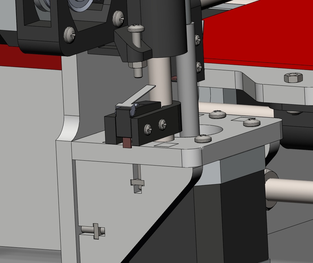
Is the extruder piece upside down?

I am going to drill through my metal as the m3 holes currently can accept an m3 bolt so that means they are to large to tap m3

To unsubscribe from this group and stop receiving emails from it, send an email to 3dprintertipstricks...@googlegroups.com.

Jetguy

unread,
May 30, 2013, 10:53:56 AM5/30/13
to 3dprintertips...@googlegroups.com
I'm following both of your builds build because somewhere I do have appreciation for the oldschool Reprap design. I always said a stock Prusa (well even the Mendels I liked to build) was very weak in the X axis of the frame. Literally, no bracing at all. That giant square is about the perfect solution to that problem.
I must say, I am impressed. Also, nice RAMBO setup for the electronics.
 
For an open frame bot, I bet it will print nicely and give a lot more expensive machines a run for the money for sure. Again, top notch.
 
The picture is at a dead on angle thus it's not visible but it does have the triangular "wings" that brace that tall Z axis in Y also right?

Mark Cohen

unread,
May 30, 2013, 11:07:01 AM5/30/13
to 3dprintertips...@googlegroups.com

No braces
I think the y boltd on with a nut on each side
The wood ones have the brace

To unsubscribe from this group and stop receiving emails from it, send an email to 3dprintertipstricks...@googlegroups.com.

JohnA.

unread,
May 30, 2013, 11:18:39 AM5/30/13
to 3dprintertips...@googlegroups.com
Marc:  Yeah - my extruder piece is upside down.  Damnit. 

Jetguy:  I don't have the 'improved' frame with the big 'wings' - which I kind of wish I did have.  My Z-axis main frame stands on it's own (the steppers are like feet) and then it's also held up by the mounts on the bottom of the Y axis rods - but that's still sorta dicey.  We'll see how it operates like this?

I whipped up a 90 degree mount for the Rambo that'll mount it to the stock Arduino bolt holes - and then realized that the rambo mounting is 95mm x 96mm, and I had it spun the wrong way.   Will print another tonight...


JohnA.

JohnA.

unread,
May 30, 2013, 11:28:15 AM5/30/13
to 3dprintertips...@googlegroups.com
There's a 'single sheet' version that also has wings, I think it's referred to as the 'sgraber i3' frame:  

http://shop.seemecnc.com/images/1358004341668186270148.jpeg

Best thing about it in my mind:  more places to mount power supply and electronics. 

JohnA.
To unsubscribe from this group and stop receiving emails from it, send an email to 3dprintertipstricksreviews+unsubsc...@googlegroups.com.

To post to this group, send email to 3dprintertips...@googlegroups.com.


Mark Cohen

unread,
May 30, 2013, 11:41:36 AM5/30/13
to 3dprintertips...@googlegroups.com

Depending on your extruder their is a dainty back in the mini folder that goes along with the printed platform piece if you know the part i am talking about. It could be in the box frame folder. I am not home so I cant check it out

To unsubscribe from this group and stop receiving emails from it, send an email to 3dprintertipstricks...@googlegroups.com.

Jetguy

unread,
May 30, 2013, 11:53:56 AM5/30/13
to 3dprintertips...@googlegroups.com
You guys want some wings lasercut?
I gotta send Mark a package anyway?
Sorry, it won't be metal but maybe I can dig up some scrap acrylic or something in about 5.2mm thickness.
 
I highy recommend adding the wings. The higher the extruder goes up in Z the more chance there is for a virbration or swaying to occur and therefor tall object get bigger error at the top without them. Just my 2 cents.
 
I think there is this myth that with metal, you can remove bracing but that's exactly opposite. Bracing is what makes the frame stiff. All metals act like a spring. Machines like the Aluminatus look cool but lack bracing. The connection points are the weak spots on all these "minimal" designs.

Mark Cohen

unread,
May 30, 2013, 1:31:48 PM5/30/13
to 3dprintertips...@googlegroups.com
Thanks for the offer, but I want to build it first and see if it actually needs it as  it looks ok in Joe Prusa's videos.

To unsubscribe from this group and stop receiving emails from it, send an email to 3dprintertipstricks...@googlegroups.com.

Kurt Wendt

unread,
May 30, 2013, 3:40:10 PM5/30/13
to 3dprintertips...@googlegroups.com

Like JetGuy – I also appreciate you guys showing us your progress on building your new Bots. Its great to see W.I.P. stuff, different Bot designs – and also keep the Pics coming!


-K-


To unsubscribe from this group and stop receiving emails from it, send an email to 3dprintertipstricks...@googlegroups.com.

Jetguy

unread,
May 30, 2013, 3:49:06 PM5/30/13
to 3dprintertips...@googlegroups.com, ku...@isssusa.com
Just for declining it, there is a set going in the box. I can't make you wear them like a little kid, but at least you can say you were prepared.

On Thursday, May 30, 2013 3:40:10 PM UTC-4, Kurt Wendt wrote:

Like JetGuy – I also appreciate you guys showing us your progress on building your new Bots. Its great to see W.I.P. stuff, different Bot designs – and also keep the Pics coming!


-K-


Kurt Wendt

unread,
May 30, 2013, 3:50:23 PM5/30/13
to 3dprintertips...@googlegroups.com

OK – JetGuy – that IS Funny!


To unsubscribe from this group and stop receiving emails from it, send an email to 3dprintertipstricks...@googlegroups.com.

Mark Cohen

unread,
May 30, 2013, 4:22:36 PM5/30/13
to 3dprintertips...@googlegroups.com

Oh alright.....
Someone wants to show me his laser-fu I think!
Your ultimaker parts are on the way now.

To unsubscribe from this group and stop receiving emails from it, send an email to 3dprintertipstricks...@googlegroups.com.

JohnA.

unread,
May 30, 2013, 4:55:38 PM5/30/13
to 3dprintertips...@googlegroups.com, ku...@isssusa.com
I definitely want a set - but can't figure out how I'd attach them since the frame isn't notched / drilled for it?


JohnA.

JohnA.

unread,
May 30, 2013, 4:57:10 PM5/30/13
to 3dprintertips...@googlegroups.com
Jetguy's getting an Ultimaker to play with too?   Nice! 

Mine's been great... 


JohnA.

To unsubscribe from this group and stop receiving emails from it, send an email to 3dprintertipstricksreviews+unsubsc...@googlegroups.com.


To post to this group, send email to 3dprintertips...@googlegroups.com.


--
You received this message because you are subscribed to the Google Groups "3D Printer Tips, Tricks and Reviews" group.

To unsubscribe from this group and stop receiving emails from it, send an email to 3dprintertipstricksreviews+unsubsc...@googlegroups.com.


To post to this group, send email to 3dprintertips...@googlegroups.com.


Jetguy

unread,
May 30, 2013, 5:24:04 PM5/30/13
to 3dprintertips...@googlegroups.com
John,
Now that is funny. I always had one, a custom one and a stock one. Well, truth is, kinda mixed on both. The acrylic one I ran with stock head and stock electronics and the wooden original frame was running a gen4 electronics and MK6 Bowden hack.
I traded Mark the wooden frame returned to stock config for a T-O-M and a bunch of parts I built Ultimate T-O-Ms from. So Mark did get a real original Ultimaker. 
So I had this acrylic Ultimaker frame needing a hot end and electronics. It's going to get RAMPS+ discount LCD but use the new V2 hotend Mark just got in a bundle with parts. So it's still a Franken Ultimaker.
It will run Cura just like you guys and print the same.

Mark Cohen

unread,
May 30, 2013, 6:16:40 PM5/30/13
to 3dprintertips...@googlegroups.com

It was too complicated for me to explain....

To unsubscribe from this group and stop receiving emails from it, send an email to 3dprintertipstricks...@googlegroups.com.

JohnA.

unread,
May 30, 2013, 10:31:10 PM5/30/13
to 3dprintertips...@googlegroups.com
Fixed my extruder mount (flipped it) - mounted endstops, and took a stab at a 90 degree RAMBO mount.   Mount was too flimsy, new version is printing now.   I didn't want to start running wires neatly until I get the hot end and extruder stepper on there....


JohnA.

Joseph Chiu

unread,
May 31, 2013, 1:31:08 AM5/31/13
to 3dprintertips...@googlegroups.com
Ditto on the thanks for WIP pics!

I'm wondering, as I haven't experimented with building a complete from-scratch RepRap... Does having the three point bearings make that much of a difference over two?    The top two bearings are right up against each other - it seems like it would only give you a little more constraint than one bearing?  Also, is there any adjustability to the rod-spacing or bearing spacing to cut down on play?

Joseph


To unsubscribe from this group and stop receiving emails from it, send an email to 3dprintertipstricks...@googlegroups.com.

Mark Cohen

unread,
May 31, 2013, 6:15:53 AM5/31/13
to 3dprintertips...@googlegroups.com

Doing this for 4 years I have seen this come up once in a while. Many people like to use an even number because it just makes sense. But really less works out better to be less constraining. The two are there to drive and guide and it is 2 because you want it to be as long as the part. You want one at each end so it does not wobble. You want the single just to hold it in position and as such it gives an element of play that makes the whole thing moves smoother than having 2. If your part was narrower you might just want one bearing to drive and two round bearings to pinch it on the rods. This is also done on the heated bed.
As for two much play the trick was to put the bearings on the rods first and then zip tie them on to the parts so that everything was lined up nicely and tight. If you just reversed the part without rezip tying it wont be right I am thinking.

TheMakerGuy

unread,
May 31, 2013, 8:27:45 AM5/31/13
to 3dprintertips...@googlegroups.com
Oh I forgot the most important thing. The main reason people do this is that they can't get the rods perfectly alighned. They are always a small bit off and thats why you need a bit of play or they will bind.
To post to this group, send email to 3dprintertipstricksreviews@googlegroups.com.


--
You received this message because you are subscribed to the Google Groups "3D Printer Tips, Tricks and Reviews" group.
To unsubscribe from this group and stop receiving emails from it, send an email to 3dprintertipstricksreviews+unsub...@googlegroups.com.
To post to this group, send email to 3dprintertipstricksreviews@googlegroups.com.


TheMakerGuy

unread,
May 31, 2013, 8:49:41 AM5/31/13
to 3dprintertips...@googlegroups.com
I noticed I forgot to order the Heaterboard on ebay. I thought I did. I just ordered the MK2B as it came with the thermistor and I was not sure if I had a few lying around. Besides I may up the voltage at some point. i am going to use 13.5volts on the 12v lines my cnc power supply.

TheMakerGuy

unread,
May 31, 2013, 8:55:01 AM5/31/13
to 3dprintertips...@googlegroups.com
Glass also. I hope everything is the right size. 214mm x 214mm for the heater and 214 x 210 for the boro glass. I fugured that sounded right to exclude the solder areas.


JohnA.

unread,
May 31, 2013, 9:09:54 AM5/31/13
to 3dprintertips...@googlegroups.com
I got this board, seems like a decent deal?    I think I got a few other parts from the same vendor, and he's local-ish.

http://www.ebay.com/itm/321125865983?var=510117151920&ssPageName=STRK:MEWNX:IT&_trksid=p3984.m1497.l2649

JohnA.
To post to this group, send email to 3dprintertips...@googlegroups.com.


Mark Cohen

unread,
May 31, 2013, 9:25:23 AM5/31/13
to 3dprintertips...@googlegroups.com

He was my first choice but he didn't include the thermistor and I wanted 14 Guage wire not 16. I have 16 on hand.

To unsubscribe from this group and stop receiving emails from it, send an email to 3dprintertipstricks...@googlegroups.com.

James Armstrong

unread,
May 31, 2013, 9:36:05 AM5/31/13
to 3dprintertips...@googlegroups.com
@Jetguy: I might have to take you up on that (I'll buy the wood / plexi). Need two printed for me and coworker. I'll get with you this weekend if I have any time. Been awhile since I have been by.

- James

Joseph Chiu

unread,
May 31, 2013, 9:44:26 AM5/31/13
to 3dprintertips...@googlegroups.com
I get the 3-point thing (stable 3-legged stool vs a wobbly 4-legged) -- but it seemed like those bearings being butted up against each other wouldn't have much more of a baseline than just one bearing since they are allowed to float a bit relative to each other.  Or maybe I'm mistaken about rigidly they're held after being zip-tied into place.

On Fri, May 31, 2013 at 5:27 AM, TheMakerGuy <markc...@gmail.com> wrote:
Oh I forgot the most important thing. The main reason people do this is that they can't get the rods perfectly alighned. They are always a small bit off and thats why you need a bit of play or they will bind.

Maybe I'm lucky, but when I  put my ToM together, my rods were very nicely aligned on the X.  The Z was a problem because of the cantilevering, of course.

Thanks for your explanations!

Joseph
 

Mark Cohen

unread,
May 31, 2013, 9:49:27 AM5/31/13
to 3dprintertips...@googlegroups.com
I'm not a Jetguy nor do I play one on TV. :)
But perhaps there is an engineering reason behind it?

--
You received this message because you are subscribed to the Google Groups "3D Printer Tips, Tricks and Reviews" group.
To unsubscribe from this group and stop receiving emails from it, send an email to 3dprintertipstricks...@googlegroups.com.

Jetguy

unread,
May 31, 2013, 1:00:05 PM5/31/13
to 3dprintertips...@googlegroups.com
Here's my thoughts on the subjet and yes, take this as opinion, not some emperical fact.
On these larger beds, if you go 3 point leveling, then you assume the material and system of the bed to so strong and straight, that any force from the printed object or just mounting in general is handled by the surface itself. Obviously, the bigger the bed, the longer the distance between where the support point is and where load on the bed surface could be.
 
Moving to 4 corner mounting systems support the bed in a much better fashion and while if misadjusted, would twist the bed, most of the time, they actually support the bed and make leveling the 4 corners to a very high precision a lot easier.
 
Again, the problem with 3 point is HUGE assumptions. You assume the bed is already dead flat. You assume the 3 points of support are sufficient. You assume the 3 points are at the extreme corners or max distance of the bed.
 
If the bed is square and 3 point leveling is used, it now becomes an issue of location of the 3rd point. Most heated bed PCBs are not really made well for 3 point mounting. Then comes how do you handle clamping the glass bed to the heater PCB and not run into the 3rd point mounting in the middle of one side of the square?
 
Again, I say 4 point support is fine. You level the bed anyway, 4 point is not trying to warp the bed. Adjustment is way easier, move the nozzle as close as possible to the mounting point, adjust, then move to the next. 4 point levleing does not also adjust the other corners (within reason here), so it's one pass around the bed and it's leveled.
To unsubscribe from this group and stop receiving emails from it, send an email to 3dprintertipstricksreviews+unsub...@googlegroups.com.

JohnA.

unread,
May 31, 2013, 1:51:50 PM5/31/13
to 3dprintertips...@googlegroups.com
Definitely some great thoughts here.  I have a bed (MK2a) with 3 point holes, but will be running it 4 corners anyway.

I think people were also curious why they do 3 bearings on things like the extruder mount and bed sliders - instead of 2 or 4.  

JohnA.

Jetguy

unread,
May 31, 2013, 2:39:31 PM5/31/13
to 3dprintertips...@googlegroups.com
Goes back to the old days of the T-O-M with those (non)self aligning bushings (talk about false advertising).
With printed parts or even laser cut parts, it's very easy to have some warpage and not have dead parallel rods. Given that some bushings bind with even some misalignment, moving to 3 generally ensured the axis was not "overconstrained". The problem is, most implementations are still overconstrained, then is starts to become a false sense of design cue.
With linear ball bearings, they will tend to flex the rod rather than drag like a bushing and the hole point becomes moot really.
 
Ed gives the best background on this http://softsolder.com/?s=overconstraint
 
The point is, one side must ONLY roll or contact in one direction or axis. By that, I mean one side should be 2 linear bearings and the other side needs to be 2 rollers, not linear bearings. So technically, 90% of the designs out there are wrong.

JohnA.

unread,
May 31, 2013, 10:30:42 PM5/31/13
to 3dprintertips...@googlegroups.com
Parts didn't show up today - maybe tomorrow.   Took some time to work on a few bits anyway...

Printed a PSU cover to keep hands off the terminals - clear PLA:   http://imgur.com/UjowKyq

Printing (currently) a much more beefy Rambo mount to bolt to the i3 arduino mounting point.   http://imgur.com/I9kY1oR  - the previous version was too flimsy.    As long as this one fits I'll likely run it for now, even if it's not perfect.   

Soldered up some HXT connectors to nice fat power cables - so now I can disconnect the PSU from the RAMBO for transportation, or swap out to a longer cable to hide the PSU, etc:   http://imgur.com/TBL38nL   


JohnA.

JohnA.

unread,
Jun 1, 2013, 10:17:34 AM6/1/13
to 3dprintertips...@googlegroups.com
Feel free to shut me up if I'm giving too many updates....

Absolutely horrible print of a Rambo mount, but it works great.   Not sure what was up with the Replicator....   http://imgur.com/Os3o8DR

Started cleaning up endstop wiring, etc.   http://imgur.com/yaZhUr4

It's coming together.    


JohnA.

Wingcommander (whpthomas)

unread,
Jun 1, 2013, 11:56:01 AM6/1/13
to 3dprintertips...@googlegroups.com
No please keep posting I am following and enjoying each episode =)

Jetguy

unread,
Jun 1, 2013, 12:17:50 PM6/1/13
to 3dprintertips...@googlegroups.com
John, that looks amazing. Those printed parts of the machine look really nice in yellow.
 
Please,  do not take this the wrong way. You guys asked me a lot of questions on what I think about various design ideas in general and those last pics point  out another topic.
Personally, I'm not a huge fan of any dual motor axis. The reason is simple, when the bot is powered off, nothing keeps the axis aligned square to travel if either of the motors move even a step while not powered and locked or being gang moved together.
The pitch of the threaded rods you guys use are very fine, so it's not as bad and the motors are unlikely to move at all from force on the axis again, due to the fine pitch.
I actually modified my oldschool Makergear Prusa to not use 2 motors and connected both threaded rods with a Cupcake Z belt and 3 pulleys

The big why, behind this again is that on a Prusa or a lot of other designs, the entire X gantry moves in Z, and of course the extruder moves in X. If Z ever gets to be not 90 degrees because one threaded rod or the other motor gets out of perfect sync, then you end up needing to tram the machine. This also forces all moves of Z must be under power via a control panel. You really cannot move the Z axis by turning a knob and certainly not ever when the bot is off, or else you end up needing to tram the bed/ axis again before printing.
By using a belt, I can move the axis by hand and provided the belt never slips, it should remain trammed.

Jetguy

unread,
Jun 1, 2013, 2:37:22 PM6/1/13
to 3dprintertips...@googlegroups.com
Sorry for hijacking but I have to thank Mark. Next pics will be some Prusa I3 frames/braces for you both!


Mark Cohen

unread,
Jun 1, 2013, 3:53:55 PM6/1/13
to 3dprintertips...@googlegroups.com

That worked out nice
I figured out my my wire problems I think
Works out the bowden tube slips up from the front where it connects to the head leaving an inch gap
The wires are ziptied to the bowden
So I guess it pulls on the wires
I cut off the zip ties now

On Jun 1, 2013 2:37 PM, "Jetguy" <vernon...@gmail.com> wrote:
Sorry for hijacking but I have to thank Mark. Next pics will be some Prusa I3 frames/braces for you both!


--
You received this message because you are subscribed to the Google Groups "3D Printer Tips, Tricks and Reviews" group.
To unsubscribe from this group and stop receiving emails from it, send an email to 3dprintertipstricks...@googlegroups.com.

Mark Cohen

unread,
Jun 1, 2013, 4:05:05 PM6/1/13
to 3dprintertips...@googlegroups.com
I am reprinting a few parts as some of mine looked a bit drippy. It works out that turning off Retract on Jumps only and turning off Enable hop on move gives me a much more precise piece.
I drilled out the 3m holes. It looks like m3x16 bolts work nice to pass through the metal. I noticed I did not have m10 nuts with the correct pitch for the m10 rods for the base. I went over to Lowes and they had M10s with 1.5 pitch which worked fine. I had 1.25 pitch in my parts box and that did not work.
 
These look like good ideas:
http://www.thingiverse.com/thing:37272  <- This one I am going to print and try.


Mark Cohen

unread,
Jun 1, 2013, 4:07:07 PM6/1/13
to 3dprintertips...@googlegroups.com
Is anyone else noticing google groups through a browser is not functioning?

Joseph Chiu

unread,
Jun 1, 2013, 4:29:10 PM6/1/13
to 3dprintertips...@googlegroups.com

I help with the bukobot that is at the LA Makerspace. We recently had a problem where it went out of whack. . Turned out the two z steppers got turned out of sync (most likely by some unknowing person) causing prints to get way out of whack. 

I don't think the z loading is too much when the machine is in normal operation, but my own experience is that if the z screwleads are accessible, it could potentially lead to the z being way off kilter.

To unsubscribe from this group and stop receiving emails from it, send an email to 3dprintertipstricks...@googlegroups.com.

Jetguy

unread,
Jun 1, 2013, 5:18:17 PM6/1/13
to 3dprintertips...@googlegroups.com
I'm using the browser all the time, but,, I do get the error and then hit refresh a lot.
To unsubscribe from this group and stop receiving emails from it, send an email to 3dprintertipstricksreviews+unsub...@googlegroups.com.

JohnA.

unread,
Jun 1, 2013, 10:22:25 PM6/1/13
to 3dprintertips...@googlegroups.com
I definitely understand the 2 z-motor issue.  Hell, just assembling it I've been wondering how I'm expected to get it level.   It's close, but I'm sure it's not 'right' yet.     The belt-driven prusa is wild looking.  Man, I have all of those parts around - so many cupcake parts, especially after I went to the z-rider.   

J-Head MKV showed up today - but my extruder stepper that was supposed to arrive yesterday is still missing.   Do people insulate the heads on these things with the fiberglass tape  / insulation stuff?  

JohnA.

Jetguy

unread,
Jun 2, 2013, 1:55:15 AM6/2/13
to 3dprintertips...@googlegroups.com
Well, I just spent several hours with James Armstrong and came up with a new killer Z mod using Cupcake Z belt as I had suggested.
Well, he need to post the derivative of this mod.

Jetguy

unread,
Jun 2, 2013, 3:18:13 AM6/2/13
to 3dprintertips...@googlegroups.com
BTW, pics

So that was the basic mockup at the top.
We use 3 5x11x4 flanged bearings, GT2 36T pulleys (5mm bore), 4 each 624 bearings for the idlers, A cupcake Z belt GT2 2mm, 6mm wide 424 teeth, 5 to 5mm shaft coupler,
What is not shown, is that at the bottom where the motors mount, on the right side there will not be a motor so the motor plate was changed to hold another 5mm bearing, the left side motor will drive that rod and transfer the torque to the right side via the belt. The left back idler is in a slot to adjust belt tension. Very nice and somewhat the same idea on the older Mendel with the idlers. Also Ultimachine has those nice large M4 washers (fender washers). Adafruit sells the 36 tooth pulleys and SDP-SI has the Cupcake z belts and they also carry the pulleys. bearings at VXB.


Prusa_i3_Frame_V2_Laser_Cut_Layout_extend_moded.dxf

Joseph Chiu

unread,
Jun 2, 2013, 9:20:42 AM6/2/13
to 3dprintertips...@googlegroups.com
I remember reading from Whosawhatsis and others on the 3D Printing community on G+ that constraining the Z screwleads at the top and bottom is a Not Good Thing - that you increase the wobble/deflection that can show up as wobbling in the XY plane, or even contributing to some Z errors.  Just wanted to mention that in case it wasn't already considered.

Nice macro shots of the work!  I can almost steal your fingerprint! :)


--
You received this message because you are subscribed to the Google Groups "3D Printer Tips, Tricks and Reviews" group.
To unsubscribe from this group and stop receiving emails from it, send an email to 3dprintertipstricks...@googlegroups.com.

Jetguy

unread,
Jun 2, 2013, 11:54:04 AM6/2/13
to
Good point on the constraint thing, James and I were talking about that and I said I always like to put the constraint at the top (nuts or the pulleys on the top side of the top bearings) and less the mass (the X gantry) hang below. Now that you say this, with only 5mm diameter screws, it's even more important than the days when I used 8mm screws. That then brings up an interesting and new question as well.
The stock design then does it all wrong IMO. They use tubing as the coupler, which actually is a very good idea, but then that was the only connection to the threaded rod or constraint in most of the pictures I saw. They didn't specify using flanged bearings and the top bearings were just press in and hope is stays. This meant the threaded rods where in compression, the support was at the motors  and through the tubing coupling. Even if during assembly you pushed the the threaded rod agaisnt the motor shaft, depending on the shape of the ends of the shaft and the threaded rod could attempt to push the rod out of being concentric. The devil is in the tiny details like this.
 
So basically, I have always thought of the threaded rod like a wire and always tried to keep it in tension rather than compression. So that means I actually disagree just a tiny bit in that constraining both ends of the rod is OK, but its how you do it that matters. The constrant needs to be on the outside edges of the frame, basically the extreme top and bottom of the threaded rods.
 
Which then turns into the corrrect way to use these http://www.adafruit.com/products/1175 . You still want to ensure those are ONLY used in tension with the constraint at the far end of the rod (AKA the top in this case) and when tighten the stetscrew at the motor half, just barely pull down on the botom half of the coupler collar to put tension on the threaded rod when locked down.
 
Consider this just Jetguy's thoughts on mechanics.
To unsubscribe from this group and stop receiving emails from it, send an email to 3dprintertipstricksreviews+unsub...@googlegroups.com.

Joseph Chiu

unread,
Jun 2, 2013, 11:11:08 AM6/2/13
to 3dprintertips...@googlegroups.com
Thanks Jetguy.  When I was typing my earlier message, that's what I had in my head -- that you should be running wires (or threaded rods which, in my opinion, are just beefier wires with threads on them) under tension than compression...  And that the bottom should be the vertically floating element, while still being rotationally constrained...


On Sun, Jun 2, 2013 at 7:07 AM, Jetguy <vernon...@gmail.com> wrote:
Good point on the constraint thing, James and I were talking about that and I said, I always like to put the constraint at the top (nuts or the pulleys on the top side of the top bearings) and less the mass (the X gantry) hang below. Now that you say this, with only 5mm diameter screws, it's even more important than the days when I used 8mm screws. That then brings up an interesting and new question as well.
The stock design then does it all wrong IMO. They use tubing as the coupler, which actually is a very good idea, but then that was the only connection to the threaded rod or constraint in most of the pictures I saw. They didn't specify using flanged bearings and the top bearings were just press in and hope is stays. This meant the threaded rods where in compression, the support was at the motors  and through the tubing coupling. Even if during assembly you pushed the the threaded rod agaisnt the motor shaft, depending on the shape of the ends of the shaft and the threaded rod could attempt to push the rod out of being concentric. The devil is in the tiny details like this.
 
So basically, I have always though of the thread rod like a wire and always tried to keep it in tension rather than compression. So that means I actually disagree just a tiny bitm in that constraining both ends of the rod is OK, but its how you do it that matter. The constrating needs to be on the outside edges of the frame, so extreme top and bottom of the threaded rods.
 
Which then turns into the corrrect way to use these http://www.adafruit.com/products/1175 . You still want to ensure those are ONLY used in tension with the constraint at the far end of the rod (AKA the top in this case) and when tighten the stetscrew at the motor half, just barely pull down on the botom half of the coupler collar to put tension on the threaded rod when locked down.
 
Consider this just Jetguy's thoughts on mechanics.

On Sunday, June 2, 2013 9:20:42 AM UTC-4, Joseph Chiu wrote:
To unsubscribe from this group and stop receiving emails from it, send an email to 3dprintertipstricksreviews+unsub...@googlegroups.com.
To post to this group, send email to 3dprintertips...@googlegroups.com.


Mark Cohen

unread,
Jun 3, 2013, 11:00:08 AM6/3/13
to 3dprintertips...@googlegroups.com

Hi,
Could you send me the file for the mount? The one on thingiverse isnt as cool as yours.
Also I am ordering a cubd extruder as jetguy is going to try and make me an aluminum angle iron adapter.
Thanks

--

You received this message because you are subscribed to the Google Groups "3D Printer Tips, Tricks and Reviews" group.

To unsubscribe from this group and stop receiving emails from it, send an email to 3dprintertipstricksreviews+unsubsc...@googlegroups.com.


To post to this group, send email to 3dprintertips...@googlegroups.com.


--
You received this message because you are subscribed to the Google Groups "3D Printer Tips, Tricks and Reviews" group.
To unsubscribe from this group and stop receiving emails from it, send an email to 3dprintertipstricksreviews+unsubsc...@googlegroups.com.

To post to this group, send email to 3dprintertips...@googlegroups.com.


--
You received this message because you are subscribed to the Google Groups "3D Printer Tips, Tricks and Reviews" group.
To unsubscribe from this group and stop receiving emails from it, send an email to 3dprintertipstricksreviews+unsub...@googlegroups.com.
To post to this group, send email to 3dprintertips...@googlegroups.com.


TheMakerGuy

unread,
Jun 3, 2013, 11:45:26 AM6/3/13
to 3dprintertips...@googlegroups.com
@JohnA,
By the way, how are you mounting the endstops. I can't seem to find a good mount or pictures.
Thanks.
To post to this group, send email to 3dprintertipstricksreviews@googlegroups.com.


TheMakerGuy

unread,
Jun 3, 2013, 12:07:41 PM6/3/13
to 3dprintertips...@googlegroups.com
@JetGuy
 
Here is a cut and paste from the reprap forum with pics showing the adapter.
 
 
Re: Prusa i3 Extruder?
January 21, 2013 11:57AM
Registered: 5 months ago
Posts: 6
I just built my I3 last week from lazer cut frame. I used Qu-BD extruder but replaced the gear with mk8 and replaced the feed parts. It works really nice now. I had to make a new mount from a piece of angle channel because using the universal mount for the I3 puts the extruder in the middle and the hot end on the QU-BD is very short so I had to fix it to hang below the bottom slide rail. I just about have it calibrated perfect the only issue I am working on now is on larger prints the abs is warping.
Here are some pics of my build

Prusa I3 Pic 1
Prusa I3 Pic 2

James Armstrong

unread,
Jun 3, 2013, 12:32:55 PM6/3/13
to 3dprintertips...@googlegroups.com
So your going with the bowden setup Mark? I was hoping to use a direct drive because it was the bowden part of the rostock that was giving me problems with oozing. 

Mark Cohen

unread,
Jun 3, 2013, 12:34:16 PM6/3/13
to 3dprintertips...@googlegroups.com

I was talking about my ultimaker

Mark Cohen

unread,
Jun 3, 2013, 1:33:15 PM6/3/13
to 3dprintertips...@googlegroups.com

I still have an extra steves extruder and hot end parts lying around

Jetguy

unread,
Jun 3, 2013, 2:26:06 PM6/3/13
to 3dprintertips...@googlegroups.com
BTW, more work last night published today http://www.thingiverse.com/thing:98127
Can't wait to see one of these put together.
To unsubscribe from this group and stop receiving emails from it, send an email to 3dprintertipstricksreviews+unsub...@googlegroups.com.

Jetguy

unread,
Jun 3, 2013, 2:32:39 PM6/3/13
to 3dprintertips...@googlegroups.com
OK, exactly as I thought. I'll have some cranked out tonight in aluminum angle.
If I had my CNC mill up and running, I could make even quicker work of this.
 
BTW, can you guys link what STL you are using for the X carriage? Is there a standard mounting pattern or something?
I mean most I've seen are geared extruders and I assume that integrated in.
To post to this group, send email to 3dprintertips...@googlegroups.com.


Mark Cohen

unread,
Jun 3, 2013, 5:25:04 PM6/3/13
to 3dprintertips...@googlegroups.com
 
x-carriage.scad
 
But you will need to build it. I can send as stl when I get home.

To unsubscribe from this group and stop receiving emails from it, send an email to 3dprintertipstricks...@googlegroups.com.

Jetguy

unread,
Jun 3, 2013, 5:49:26 PM6/3/13
to 3dprintertips...@googlegroups.com
OK, FWIW, the "standard" seems to be 30mm between mounting holes. A NEMA17 (AKA standard MK7 or clone) is 42mm edge to edge. This either means the mounting holes are behind the extruder motor making it stick out a tiny bit further, or, using the SCAD to make it say 50mm mounting clears the motor making it easier to attach detach. Not sure what that does to carriage width and therefore X print area.
 
I'm printing parts both ways and measuring so hold off on printing X carriage until I know OK?

Jetguy

unread,
Jun 3, 2013, 6:17:01 PM6/3/13
to 3dprintertips...@googlegroups.com
BTW, there is another option too.
Why screw around with printed parts and an aluminum frame when you could use 3 of these http://www.adafruit.com/products/1179
Plus this aluminum angle and be done with the most solid carriage ever for a MK7/clone.

Jetguy

unread,
Jun 3, 2013, 6:47:10 PM6/3/13
to 3dprintertips...@googlegroups.com
OK, for a plastic X, I think this set here is the best I have seen for doing this MK7 http://www.thingiverse.com/thing:74983  It already has wide holed for the mount that should clear a NEMA17 on both sides easy.
The pictures of the one design up looked like it used the universal mount seen here http://www.qu-bd.com/tutorials/mbeassemblypics/
I'm wondering length or if I just cut the slots in the aluminum directly. Knowing what I know about thermal design of the extruder, in theory, in the aluminum is best. The only factor is, some heat gets transferred  so I wouldn't use PLA for the X carriage if I could help it.


Mark Cohen

unread,
Jun 3, 2013, 7:48:41 PM6/3/13
to 3dprintertips...@googlegroups.com
To unsubscribe from this group and stop receiving emails from it, send an email to 3dprintertipstricks...@googlegroups.com.
x-carriage.stl

Mark Cohen

unread,
Jun 3, 2013, 8:27:31 PM6/3/13
to 3dprintertips...@googlegroups.com

Actually 30mm is from the center of each hole

JohnA.

unread,
Jun 3, 2013, 9:39:27 PM6/3/13
to 3dprintertips...@googlegroups.com
That linear bearing platform looks great, and is a lot cheaper than I remember them being.   Damn.

Mark - I put my RAMBO mount up, in case you need it:  http://www.thingiverse.com/thing:98280

Just got home from giving a talk on 3D printing and maker culture, so I didn't have much time to play tonight.   Assembled extruder, seems like it'll work fine? 


I don't have appropriate bolts to hold it to the X carriage, so I'll bolt it up tomorrow and then wire it up and see where it's at.  

Might have it printing this week?

JohnA.

Mark Cohen

unread,
Jun 3, 2013, 10:09:02 PM6/3/13
to 3dprintertips...@googlegroups.com

Thanks!

To unsubscribe from this group and stop receiving emails from it, send an email to 3dprintertipstricks...@googlegroups.com.

Mark Cohen

unread,
Jun 3, 2013, 10:12:30 PM6/3/13
to 3dprintertips...@googlegroups.com

I didnt realize adafruit had the 5mm to 5mm spring couplers so I ordered from ebay in Hong Kong.
Oh well
I did buy by mistake 5mm to 8mm

Jetguy

unread,
Jun 4, 2013, 10:03:28 AM6/4/13
to 3dprintertips...@googlegroups.com
That's OK, we are all learning. I'm so used to regular Reprap being 8mm, I'm now not sure those parts are sized for LM8uus. I have some lying around and printed 2 common versions of the X carriage.
The one on the right is from here "Prusa i3 - STLs for Improved Laser Cut Frame Design" http://www.thingiverse.com/thing:40064
Specifically this STL, ahem, it looks liek they changed it so the main pics shows that part on the right, the new part pusblished online is different this morning!!! This one is basically the same http://www.thingiverse.com/thing:65167
 
If you want MK7, I say don't use that one. This is the one on the left http://www.thingiverse.com/thing:74983
The point should be clear, the main mounting hole spacing is much wider and clears the standard NEMA17. This then allows the motor to sit flush against the back of the aluminum angle and I can cut matching slots in the angle much like the Bracket. In theory, this also allows for dual MK7/8s


Again, I'm still mocking this up. There are lots of carriages that will work. I'm trying to explore what standards are out there for mounting though. Obviously we can go custom from a SCAD file, but I'd rather go with a semi accepted standard.
And with that I need to print some more parts and really mock this up before cutting the bracket. I ahve high confidence it will work great, I mean there is one example already in the wild, but I think I make it even nicer.
Also, can someone confirm rod sizes? I printed an X idler end and 2 carriages, none of that seems to be sized correctly for 8mm rod and LM8uus.  The X idler was from here http://www.thingiverse.com/thing:40064
According to here they should be 8mm but it sure was way off for me http://twelvepro.com/index.php?route=product/category&path=61 
 
My X ends would have cracked or I would have to drill them for 8mm rod to fit, the LM8UUS is ziptied would definitely crack the X carriage when tightened down. It could be a slicing error on my part, but I doubt it, everything else was dead on.


TheMakerGuy

unread,
Jun 4, 2013, 10:53:20 AM6/4/13
to 3dprintertips...@googlegroups.com
That part on thingiverse is for a different extruder.
The rods are 8mm and all the bearings fit fine. My X is already assembled.
The angle bracket looks too short to me in the picture it should connect to the two bolt holes in the x carriage and hang extend below the bottommost rod because the hot end is so short on the QUBD/MK7 extruders.

JohnA.

unread,
Jun 4, 2013, 10:09:57 PM6/4/13
to 3dprintertips...@googlegroups.com
Update!


- Wiring is just temporary to make sure everything functions
- All axes move, all endstops work (had a few plugged in wrong at first)
- Extruder turns
- Hot end heats up FAST.  Did the marlin auto-tune, edited PID details
- HBP heats up fast too.
- Fan works
- Thermistors work, etc.  

Next steps:

- clean up wiring
- see if it'll extrude
- set z-endstop height
- mount glass
- try to print....

JohnA.

JohnA.

unread,
Jun 5, 2013, 6:51:59 AM6/5/13
to 3dprintertips...@googlegroups.com
Couldn't go to bed with the wires that messy.    Started cleanup....


Tonight it'll print, or at least extrude...

Mark Cohen

unread,
Jun 5, 2013, 8:28:26 AM6/5/13
to 3dprintertips...@googlegroups.com
Nice.
I am about a week behind you.
I just got the heated bed.
I should be close to where you are on the weekend.
Would you happen to have pictures of the endstops?
 
Thanks.

James Armstrong

unread,
Jun 5, 2013, 9:53:19 AM6/5/13
to 3dprintertips...@googlegroups.com
Don't know if this helps. I zoomed into the cad file. 

To unsubscribe from this group and stop receiving emails from it, send an email to 3dprintertipstricksreviews+unsub...@googlegroups.com.

Mark Cohen

unread,
Jun 5, 2013, 10:21:25 AM6/5/13
to 3dprintertips...@googlegroups.com

Oh i think I saw that mod on thingiverse but I did not see it in the joes git. Maybe I missed it

To unsubscribe from this group and stop receiving emails from it, send an email to 3dprintertipstricks...@googlegroups.com.
It is loading more messages.
0 new messages