Steppers are complicated
1,669 views
Skip to first unread message

Ryan Carlyle
Jan 25, 2015, 10:32:05 PM1/25/15
to 3dp-...@googlegroups.com
The more I dig into stepper/driver theory, the more I realize how insanely complex the system-level behavior can be.
The big problem with steppers is the fact that the PWM current choppers in the drivers are quirky and interact with the motor specs and PSU voltage in some non-obvious ways. Specifically, the low-end driver chips we tend to use for 3DP (eg A4988, DRV8825) have current chopper duty cycle constraints that often keep them from hitting particular current levels.
First, some basics.
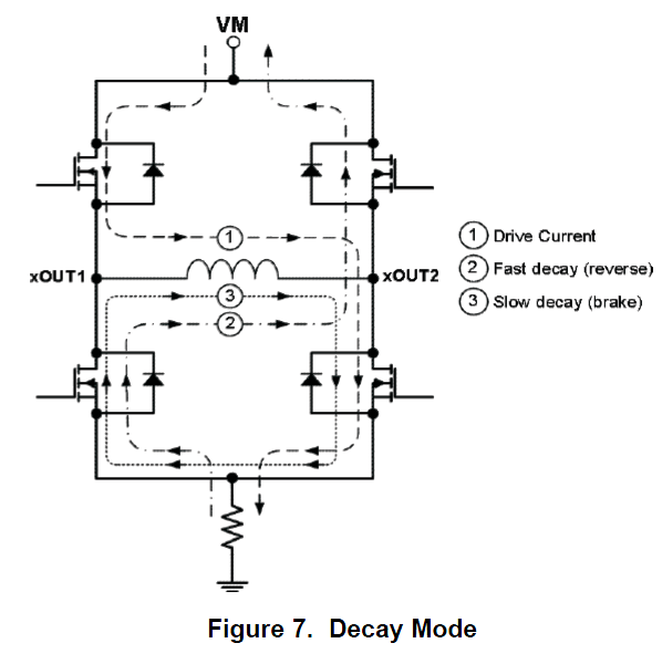
To regulate current, the current chopper can do three things:
- Apply full PSU voltage to the coil to try to raise the current -- equilibrium current calculated via V=IR
- Recirculate coil current through a low resistance to brake the motor and decrease the current (slow decay) -- equilibrium current is 0
- Apply opposite PSU voltage to the coil to reverse-drive the motor and decrease the current (fast decay) -- equilibrium current from V=IR again but in the opposite direction
From the DRV8825 datasheet:
When you do any of the above, the current through the coil will gradually shift in the direction of the equilibrium current for those conditions. How fast the coil current changes depends on:
- Motor inductance
- Motor resistance
- PSU voltage
- Fast vs slow decay mode
- What the instantaneous current is at that moment
The rate of current change is a typical first-order charge/decay curve. The farther the current is away from equilibrium, the faster it changes. After a long enough time, it settles out at the equilibrium value. (Asymptotically approaches it, anyway.) So all the driver's PWM current chopper has to do to regulate current is alternate between on/off modes to switch between different equilibrium currents, and the actual current will be maintained in an intermediate band near the setpoint.
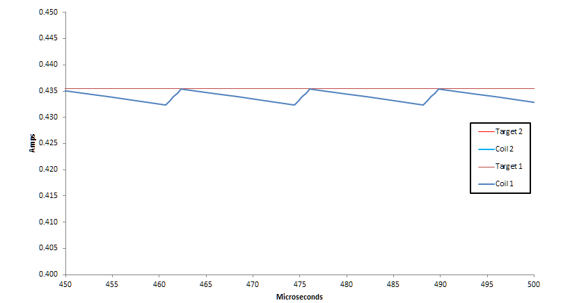
"Slow decay" mode looks like a typical PWM waveform:
"Mixed decay" mode is a little more interesting:
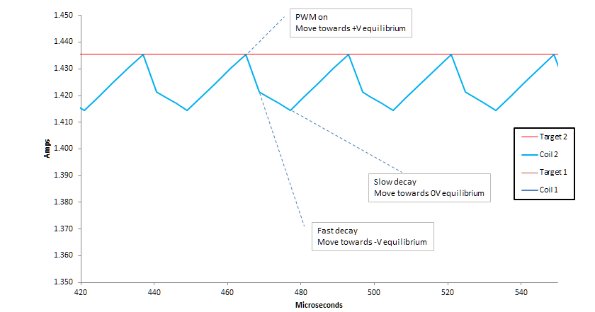
Note that these PWM waveforms look like a series of straight lines, but are actually very short segments of first-order curves. The current is always asymptotically approaching an equilibrium, but slows down its rate of change the closer it gets.
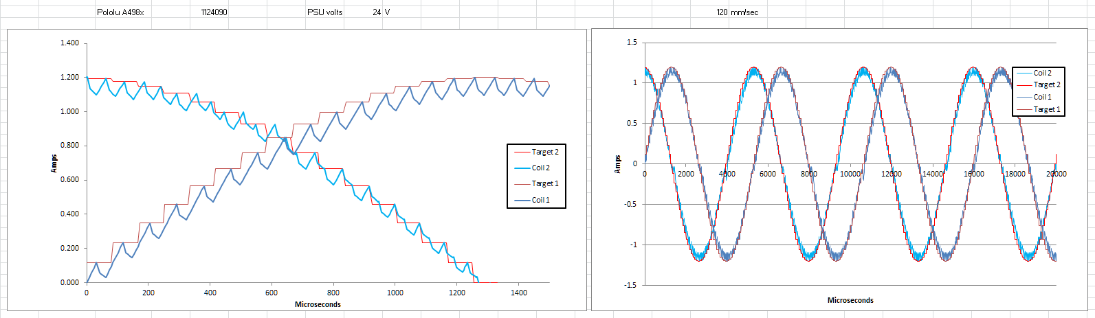
So that's all well and good. In theory, the driver modulates the currents, and the stepper can be microstepped by feeding the coils a roughly sinusoidal series of currents, 90 degrees out of phase. Like this:
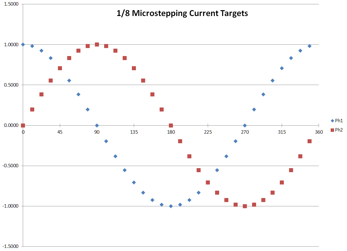
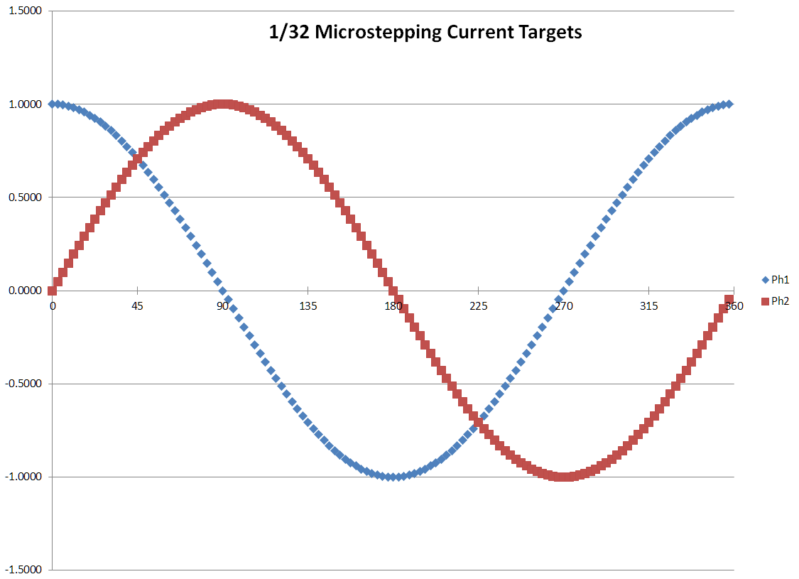
You can see how the current must be controlled to a pretty fine resolution -- very small error as a percent of full scale -- for this microstepping pattern to come out right. 1/32 stepping requires sub-0.1% current regulating precision to hit the peak current targets. If the currents are too high or too low, the stepper will have the wrong torque and/or rotate slightly out of the proper position.
The problem is, there are constraints on how long the driver can be in any of those three chopper modes. That affects the range and precision of current regulation. For the Pololu A4988, you have:
- Minimum on time: ~1 µs
- No maximum on time: current will rise until it hits the target
- Fixed off time on rising current microsteps: ~12 µs slow decay
- Fixed off time on falling current microsteps: ~4 µs fast decay and then ~8 µs slow decay (mixed decay mode)
Those parameters are set by the driver chip and the carrier board configuration. Based on these limits and the motor characteristics, there are a variety of reasons you might have trouble hitting particular current targets:
- If motor coil resistance is too high for the voltage, you can't exceed the V=IR current and will not hit high-current microsteps. (See Ed Nisley's blog post)
- If the PSU voltage is too low for the motor inductance and resistance, current might not rise fast enough to hit rising current targets within the time allotted for each microstep
- If the PSU voltage is too high for the motor inductance, the minimum on-time will make the current tend to overshoot the target and skip low-current microsteps
- Slow decay mode might not drag down the current fast enough to hit falling current targets within the time allotted for each microstep
- Fast decay mode might drag down the current too fast, so the average output is way below the target
All of these things cause banding/ripple patterns on prints (usually called "stepper clipping") and generally cause louder/harsher stepper noise. Sometimes you get excess heat production, sometimes you get reduced torque.
Unfortunately, all of these issues vary greatly with the motor speed. Back-emf reduces the effective voltage at higher RPMs. Faster microstepping gives less time for the current to settle towards its equilibrium value, which can help or hurt depending on various system parameters.
High-resistance, high-inductance steppers are simply unsuitable for high-step-rate precision motion applications. You just can't push enough current, and the top part of the sine wave gets cut off. Here's a diagram from Ed's blog post (linked above):

The grey line is the desired microstepping current, the red line is the actual current (limited by high resistance or low voltage), and the pink bands are sections where step commands cause no stepper rotation whatsoever because both coil currents are maxed out. In this case, there are several possible fixes:
- Switch to a lower-resistance stepper
- Raise the supply voltage
- Reduce the driver current setting, so the peak of the current curve is below the limit (reducing the target below the max eliminates the clipping distortion)
This specific issue has promoted a general rule of thumb in the 3DP community: low-inductance steppers are better. That's good advice, but very much over-simplified.
Another common issue is missed low-current microsteps. The stock Pololu A4988 uses slow decay mode on rising-current microsteps. (The parts of the cycle where current targets are rising up the sine curve with each microstep.) And slow decay is really bad at dropping low currents -- they're already so close to zero that the current drops slowly. Whereas the PWM-on period is quite far from the equilibrium +V current, so the current rises very quickly. With high supply voltage and low inductance motors, this means current rises too much during the 1 µs minimum on-time for the 12 µs fixed off-time to drop it back down. When the motor is stationary, this means the driver simply can't keep the current from rising above the target.
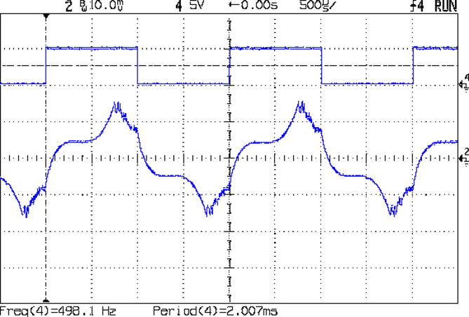
The A4988 datasheet even has a specific note about this. Here's the oscilloscope waveform:

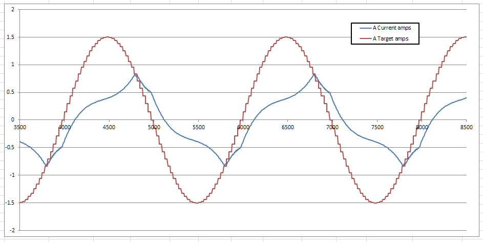
That chart makes it look like the current goes straight past the low current targets on rising microsteps. But that's because their demo stepper is turning very slowly. In fact, the stepper cannot stop on the microsteps where the current is not properly limited by the PWM chopper. It will sit a little ahead of the desired microstep position. But with more realistic step rates for 3D printing, the rise time for the "uncontrolled" current is only a little faster than the stepping rate changes the target current. So it looks more like this simulator output:

Note how the PWM chopper is running at minimum duty cycle in slow decay mode, but can't help but let the current slowly rise. Then for falling microsteps where mixed decay mode is used, it works just fine. Only the low-current rising microsteps are getting excess current, and even then, only when the microstepping rate is slower than the current rise. This problem should only happen at low stepping speeds.
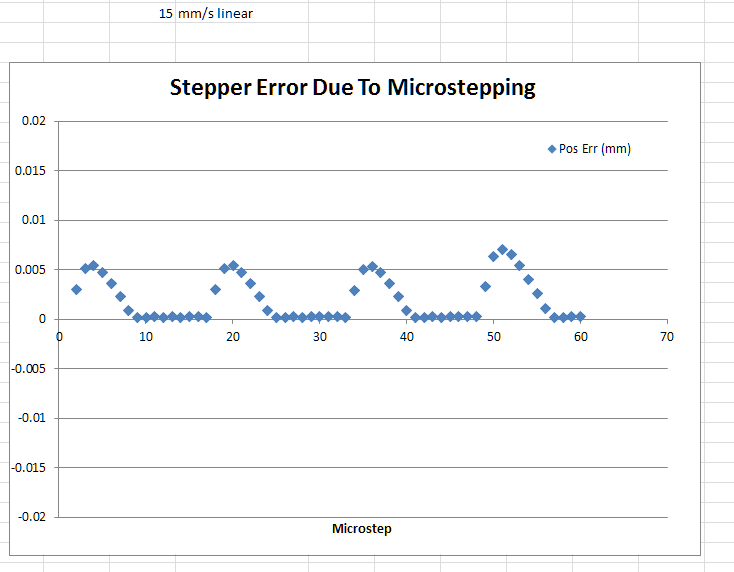
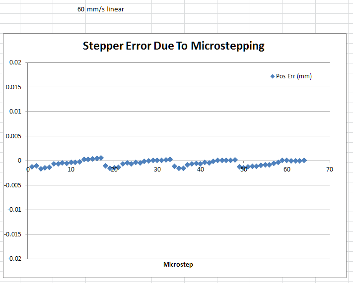
Having some excess current on one coil produces position error. Specifically, the rotor runs slightly ahead of the desired position for a while, which generates a ripple pattern in the print. The error my simulator is predicting is small, but would be visible in perimeters:
And you can see this effect in people's prints when they run their printer at extremely low speeds. Here's a low-speed UM2 print with visible stepper ripple (zoom in):
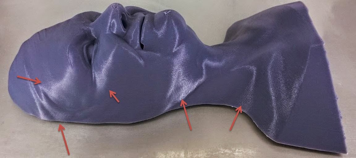
Print photo courtesy of Joel Mongeon in this thread. Here's another, from my CoreXY at about 40mm/s or so (zoom in):
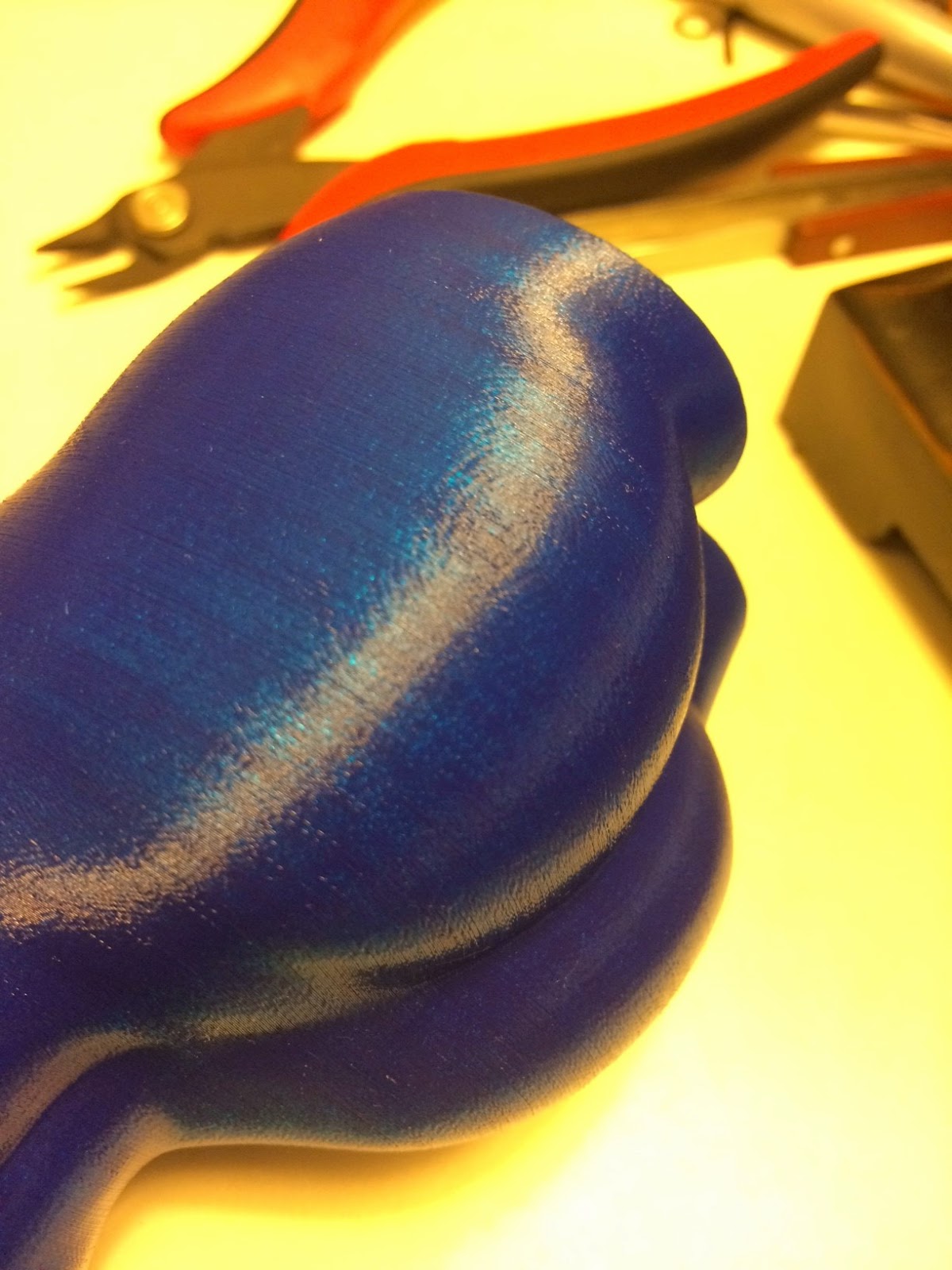
You can tell it's stepper ripple because, if you flattened the print down to a 2D contour map, you could see the ripples are aligned along a grid pattern with the XY stepper full step positions. Normally, that's around a 0.2mm spacing, but when the print has surface contours oblique to the XY motor axes, the ripples gets spaced out to be quite visible.
To fix this, you can do a few different things:
- Drop the supply voltage
- Get a motor with higher inductance and/or resistance
- Run the stepper faster
- Switch the stepper driver to "low current microstepping" mode by solder blobbing across a resistor on the carrier, so you get mixed decay on rising current microsteps
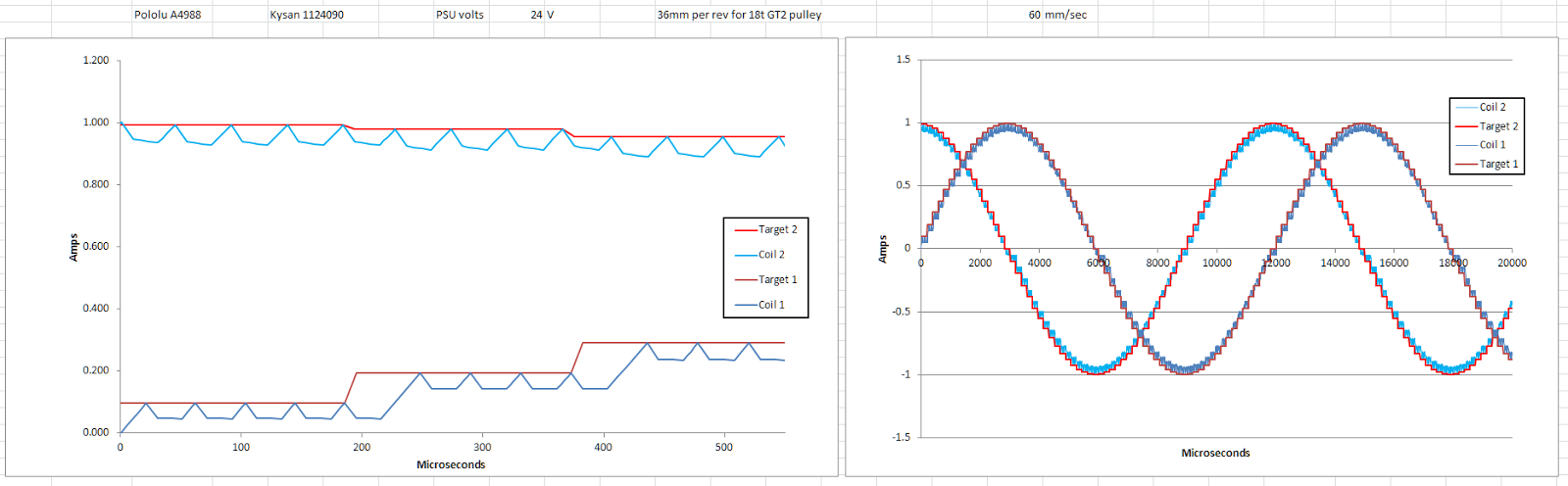
Running the printer faster is probably the easiest solution. Low current microsteps won't be exactly right, but they'll be close enough. Here's what that same set of parameters looks like at 60mm/s:


Whereas if you switch to low-current microstepping mode, the PWM off-time gets longer and mixed decay mode is always used. That decreases average currents quite a bit below the target:
Ok, that's not too bad, but let's stick with the normal decay settings and look at other possible issues. What happens if we run the steppers REALLY fast? Rising current microsteps won't be an issue. But new and exciting problems start to appear. Let's look at 250mm/s on my CoreXY. It's perfectly capable of that speed, but I don't want to print that fast, because the A4988's PWM chopper REALLY struggles to keep up with the step rate. You start to see some nasty phase lag:


At these high speeds, my simulator starts to get grumpy, because the currents aren't being properly regulated by the driver. There are some minor display and chopper logic glitches in the curves above if you look closely. But it's pretty close to what you should theoretically see. The biggest simulator shortcoming is probably the fact that I'm not showing how Sailfish, Marlin, and other 8bit firmwares go into double-stepping and quad-stepping mode at higher speeds. 250mm/s is 22khz microstepping frequency for my CoreXY. So it's actually quad-stepping, and my simulator doesn't show that.
What's quad-stepping? Well, for example, when Marlin passes 10khz microstepping frequency, it fires two step pulses per interrupt tick. That cuts the clock cycles needed for the stepper interrupt roughly in half so firing the steppers doesn't squeeze out all the non-interrupt processes like motion planning and heater control. When it double-steps, two step pulses are sent to the driver in rapid succession. This ticks up the current target by two microsteps. So in effect, this drops the de facto microstepping level from 1/16 to 1/8 -- via firmware. Then at 20khz microstepping frequency, it quad-steps. So that effectively means dropping to 1/4 stepping. The driver is still running in 1/16 mode, but the rapid quad pulse train means the PWM chopper's reference voltage shifts four steps at a time.
And as we all know, 1/8 or 1/4 stepping is rougher and noisier than 1/16 stepping. If you have a good ear, you can hear the printer shift stepping mode between 1x, 2x, and 4x when it hits speeds that trigger these critical microstep frequency thresholds.
So that's all nice and complicated.
This is a good place to stop and note that these errors are not particularly large compared to other motion system errors. In particular, ringing and filament blobbing and Z-wobble often introduce >10x bigger errors than stepper/driver ripples. Many people never notice stepper issues. They're usually quite faint. But even if your printer is extremely well-built and print settings are perfectly tuned, the stepper driver mechanics can still introduce visible surface ripple defects. It's one of the few parts of printer operation that cause bigger problems with slower print speeds. Lots of people mess this up, from hobbyists to major OEMs. It seems unavoidable with cheap drivers -- their PWM frequency just isn't high enough for precise current control.
I'm going to keep working on my simulator, and hopefully get some live oscilloscope current probe data to validate all the calculations. (Voltage probing says the PWM chopper is running the way I think it is, but that's no substitute for direct current waveform measurement.) And I'm going to make another version for the popular DRV8825 driver, which has different duty cycle constraints. When that's all done, I'll share some version of it with the community for design & tuning.

Whosa whatsis
Jan 27, 2015, 2:23:43 PM1/27/15
to 3dp-...@googlegroups.com
I think it's worth adding that the Z axis is a different animal. If you're using layer heights that are a multiple of your full-step length, none of this should matter for Z, unless you're using "auto bed leveling" (do you hate that term as much as I do?). When using this feature, the Z axis will be moving very slowly as X and Y move quickly. If it skips a couple of microsteps, that area will be slightly over/under-compressed, which (depending on the angle) should add enough noise to the surface to drown out the X/Y noise.
Ryan Carlyle
Jan 29, 2015, 11:48:13 AM1/29/15
to 3dp-...@googlegroups.com
Something occurred to me today that I hadn't quite registered before. The reason you see stepper rippling so much on faces set obliquely to a motor axis is because that stepper is running really slow when producing that curve. You can be running high print speeds and just hit an angle where one of your steppers is barely moving. Slower motion speeds amplify low-current microstep skipping.
Ryan Carlyle
Jan 29, 2015, 11:49:11 AM1/29/15
to 3dp-...@googlegroups.com
I have yet to figure out how exactly stepper ripping/clipping affects Deltas, but in my head it seems like it would look similar to segmentation error, and occur primarily at the edges of the build plate where carriages are moving very fast or very slow.

dan...@puptv.com
Jan 29, 2015, 12:06:48 PM1/29/15
to 3dp-...@googlegroups.com
In a delta, you will have a stepper moving very slowly any time the motion of the head is nearly parallel to a constant radius line of any of the 3 towers.
I'm really hoping we can figure out the optimal stepper parameters for the DRV8825... The very popular, very strong Kysan motors seem to clash with the DRV8825 drivers.
Daniel - http://www.TriDPrinting.com/
I'm really hoping we can figure out the optimal stepper parameters for the DRV8825... The very popular, very strong Kysan motors seem to clash with the DRV8825 drivers.
Daniel - http://www.TriDPrinting.com/
Ryan Carlyle
Jan 29, 2015, 12:37:23 PM1/29/15
to 3dp-...@googlegroups.com
That's a good point, although that should only happen when printing right below a tower, right? Everywhere else in the build area, you're almost always printing on an XY plane, so you'll be moving at a reasonable angle to the line of constant radius (sphere surface) associated with each carriage position. Z-hops could have rippling but they're not print moves, so nobody cares. I guess some of the more obscure techniques like Topolabs contour printing and wireframe printing could have issues.
I wonder if homing speed stepper reppling could throw off endstop trigger positions? How fast do Deltas usually do homing moves in the proximity of the limit switch?
I might be able to get a DRV8825 simulator together over the weekend. I want to validate the A4988 model with o-scope current probes first, and I want to re-write my numerical solution method to be way the hell more efficient. The next spreadsheet rev should be able to handle goal-seek functions without choking, which really makes optimization easier. But then the actual A4988-->DRV8825 modification should be as simple as changing the chopper period terms and Vref/Imax calculations.
dan...@puptv.com
Jan 29, 2015, 12:50:36 PM1/29/15
to 3dp-...@googlegroups.com
It turns out not to matter that you are printing on an X-Y plane, just that you are printing almost parallel with a "contour" line of a tower, or put more concisely, tangent to a carriage sphere. As you noted, when you get close to the base of the tower, everything in any direction is nearly parallel to the carriage sphere, so this jumping will be noticeable.
However, everywhere in the build space, when you have the head moving nearly tangent to the carriage sphere, you will be moving that tower's carriage very slowly, and see the effects of these jumps.
Are you making your stepper motor spreadsheet available? That would save me from having to do one myself to figure out what steppers will work best with the DRV8825 going forward.
Daniel

Dan Newman
Jan 29, 2015, 1:35:09 PM1/29/15
to 3dp-...@googlegroups.com
On 29/01/2015 9:06 AM, dan...@puptv.com wrote:
> In a delta, you will have a stepper moving very slowly any time the motion
> of the head is nearly parallel to a constant radius line of any of the 3
> towers.
>
> I'm really hoping we can figure out the optimal stepper parameters for the
> DRV8825... The very popular, very strong Kysan motors seem to clash with
> the DRV8825 drivers.
Interesting to read that. Would those happen to be the Kysan 1124090's sold
> In a delta, you will have a stepper moving very slowly any time the motion
> of the head is nearly parallel to a constant radius line of any of the 3
> towers.
>
> I'm really hoping we can figure out the optimal stepper parameters for the
> DRV8825... The very popular, very strong Kysan motors seem to clash with
> the DRV8825 drivers.
by a number of 3D printer companies? I ask since I use those, tried some
DRV8825's someone had sent me on their own PCB using TI's sample circuit
and layout from the app notes. Didn't seem to work well and I didn't want
to invest much time in what may have been an issue with the PCB/circuit and
not the 8825 itself.
Dan
whosawhatsis
Jan 29, 2015, 3:16:21 PM1/29/15
to Ryan Carlyle, 3dp-...@googlegroups.com
Wouldn't it be out between two towers that you'd see it most, i.e. as far as possible from the third tower?
This is where that tower's resolution is lowest, and thus the motor will be moving slowly. If you're printing a perimeter arc that is centered on the far tower (actually, technically the point 1 delta radius from the center in the direction of that tower), the motor won't move at all. A slight deviation from that arc will result in a large, low-resolution step of the effector toward or away from that far tower. When you're right at the base of a tower, that's where that tower's resolution is highest, because a large linear movement of the carriage results in a smaller movement of the effector, so the motor has to move faster and through more steps for a given length of linear effector movement.
--
You received this message because you are subscribed to a topic in the Google Groups "3DP Ideas" group.
To unsubscribe from this topic, visit https://groups.google.com/d/topic/3dp-ideas/qqTGMIFCKpU/unsubscribe.
To unsubscribe from this group and all its topics, send an email to 3dp-ideas+...@googlegroups.com.
To post to this group, send email to 3dp-...@googlegroups.com.
To view this discussion on the web visit https://groups.google.com/d/msgid/3dp-ideas/3dd7bac3-a952-4943-b360-eb28d0f757eb%40googlegroups.com.
For more options, visit https://groups.google.com/d/optout.
dan...@puptv.com
Jan 29, 2015, 4:36:03 PM1/29/15
to 3dp-...@googlegroups.com, temp...@gmail.com
Yes, I've heard/seen a video of trouble between the Kysan 1124090's and the DRV8825. I don't understand the issue quite yet, but am hopeful that it can be worked around.
A number of people have worked out the exact deltabot resolution pattern. As I recall, you are right where the actual highest resolution is not at the exact center, but a little ways off. It's probably not as far as as the place between two towers. However, defining the resolution for a delta printer is a little interesting. The error pattern is actually a cube on corner or 3 dimensional looking rhombus.
What the resolution patterns look like in some ways depends on how you want to calculate it, and it's not really fair to compare a delta printer's resolution or max error in cartesian coordinates.
Daniel - http://www.TriDPrinting.com/
Ryan Carlyle
Jan 29, 2015, 6:10:01 PM1/29/15
to 3dp-...@googlegroups.com
The horizontal resolution is simple to find as a function of radius from the tower and arm length. All you need is the Pythagorean theorem really.
The problem is, the resolution is anisotropic as hell. When the arm is near horizontal, your radial resolution for horizontal motions is very high but your tangential resolution for horizontal motions is very low. And each arm has a separate resolution, so the entire concept is suspect. Maybe we should specify arm steps/mm in particular directions instead.
The problem is, the resolution is anisotropic as hell. When the arm is near horizontal, your radial resolution for horizontal motions is very high but your tangential resolution for horizontal motions is very low. And each arm has a separate resolution, so the entire concept is suspect. Maybe we should specify arm steps/mm in particular directions instead.
Ryan Carlyle
Feb 7, 2015, 12:50:36 PM2/7/15
to
Data!
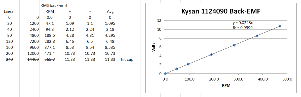
The back-emf of 0.0228 volts/rpm is slightly higher than the 0.017 volts/rpm that I guessed by looking at the torque curve. Pretty good guess though.
Ryan Carlyle
Feb 7, 2015, 4:01:25 PM2/7/15
to 3dp-...@googlegroups.com
I don't have a convenient lathe/mill to chuck up motor shafts, so made some printed parts for NEMA 17 motor testing. You wire one motor straight to your 3d printer, running a gcode file that gives you a known motor RPM for an extended period. The other motor acts as a generator and you can measure the AC RMS voltage with a multimeter. The resulting back-emf measurement is one of the inputs required for my stepper/driver simulator sheet.


This jig is overkill as far as torque capacity is concerned, but in theory you could put some electrical load on the "generator" and measure phase angle, drive efficiency, and other parameters. I'm not real interested in those though.
Ryan Carlyle
Feb 7, 2015, 4:06:53 PM2/7/15
to 3dp-...@googlegroups.com
I tested three Kysan 1124090s. Volt/rpm figures were 0.0225, 0.0234, and 0.0228. This is very good agreement and I'd say 0.023 is a good middling figure.
I also tested one Makerbot Moon's 17HD-4063-03N stepper. (Most of mine are built into things at the moment.) It had 0.0201 on one coil and 0.0205 on the other coil. So 0.020 volts/RPM seems reasonable. I'm a little surprised by how close the two types of motors are.
All the other steppers I have on hand are geared and use larger shafts. Not really worth the trouble to measure right now.

scott.e...@gmail.com
Feb 7, 2015, 5:32:38 PM2/7/15
to 3dp-...@googlegroups.com
You're using a "True RMS" meter... right?
Ryan Carlyle
Feb 7, 2015, 5:34:59 PM2/7/15
to 3dp-...@googlegroups.com
On Saturday, February 7, 2015 at 4:32:38 PM UTC-6, scott.e...@gmail.com wrote:
You're using a "True RMS" meter... right?
Yes, a true RMS Extech.
Ryan Carlyle
Feb 7, 2015, 5:45:53 PM2/7/15
to 3dp-...@googlegroups.com
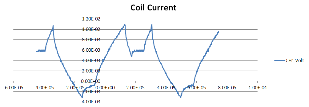
Ok, I just soldered up a couple DRV8825 boards "Botstep style" so I could pop them in my CoreXY, and put them on a scope driving my 1124090s. Turns out, the 8825s have variable off-time AND weird decay modes that aren't discussed in the data sheet. It has the normal "slow decay" curves you expect, plus some oddballs. Most of them show changing between two different decay modes on alternating PWM cycles.
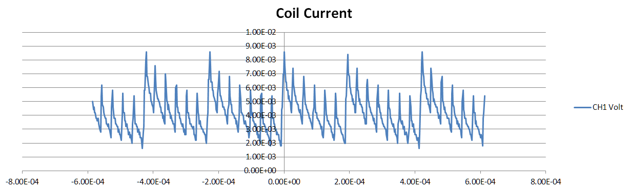 (wtf is this?)
Ryan Carlyle
Feb 8, 2015, 1:36:11 AM2/8/15
to 3dp-...@googlegroups.com
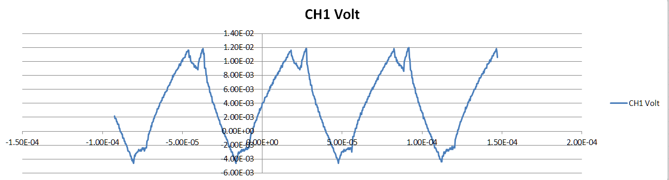
Got it sorted -- the "alternating modes" are just a property of the fixed 30 khz PWM chopper frequency. Every 33.3 usec, it turns on the chopper. When the current hits the trip target, it turns off. What it does when it turns off depends on how much time is left in the 33.3 usec. From 25 to 33.3 usec uses slow decay, and everything before that uses fast decay.
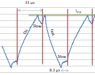
This mixed decay timing pattern creates alternating "long-short" and "short-long" periods for the on-off duty cycle. It also causes the annoying high-pitched hissing noise everyone complains about with DRV8825s.
I also tried solder-blobbing the drivers to fast decay mode. I didn't get to current measurements, but it looks like low-current microsteps get WAY less current than they're supposed to. Too much fast-decay time.
dan...@puptv.com
Feb 8, 2015, 11:11:14 PM2/8/15
to 3dp-...@googlegroups.com
Excellent work Ryan!!!
It really helps to see what's happening. Am I correct in thinking that doubling the supply voltage may be the only reasonable thing we can do to make the missed microsteps issue better?
Daniel - http://www.TriDPrinting.com/
It really helps to see what's happening. Am I correct in thinking that doubling the supply voltage may be the only reasonable thing we can do to make the missed microsteps issue better?
Daniel - http://www.TriDPrinting.com/
Ryan Carlyle
Feb 8, 2015, 11:36:41 PM2/8/15
to 3dp-...@googlegroups.com
Hmm, I think a lower voltage PSU is actually better for low speeds. The reason why low-current microsteps get skipped is because the driver's minimum on-time lets the current rise too high. Less voltage means less current rise. Alternatively, use a higher inductance / resistance motor.
And then a higher voltage PSU is better at higher speeds. Back-emf gets really significant around, say, 200mm/s.
And then a higher voltage PSU is better at higher speeds. Back-emf gets really significant around, say, 200mm/s.

Joseph Chiu
Feb 8, 2015, 11:46:12 PM2/8/15
to dan...@puptv.com, 3dp-...@googlegroups.com
Yes, ditto. I've been so wrapped up in reading that I forgot to say thanks! Really enjoying your posts on this!
Thanks Daniel for the reminder! :)
Thanks Daniel for the reminder! :)
--
You received this message because you are subscribed to the Google Groups "3DP Ideas" group.
To unsubscribe from this group and stop receiving emails from it, send an email to 3dp-ideas+...@googlegroups.com.
To post to this group, send email to 3dp-...@googlegroups.com.
To view this discussion on the web visit https://groups.google.com/d/msgid/3dp-ideas/6b015cad-5ac3-4330-80a8-115f0ff1cdeb%40googlegroups.com.

Jetguy
Feb 9, 2015, 3:46:57 PM2/9/15
to 3dp-...@googlegroups.com, dan...@puptv.com, joe...@joechiu.com
Not sure if you ever read Ed's tests on this kind of stuff. It goes on for days http://softsolder.com/page/3/?s=stepper
Especially liking your DRV8825 tests though.
On Sunday, February 8, 2015 at 11:46:12 PM UTC-5, Joseph Chiu wrote:
Yes, ditto. I've been so wrapped up in reading that I forgot to say thanks! Really enjoying your posts on this!
Thanks Daniel for the reminder! :)
On Sun, Feb 8, 2015 at 8:11 PM, <dan...@puptv.com> wrote:
Excellent work Ryan!!!
It really helps to see what's happening. Am I correct in thinking that doubling the supply voltage may be the only reasonable thing we can do to make the missed microsteps issue better?
Daniel - http://www.TriDPrinting.com/
--
You received this message because you are subscribed to the Google Groups "3DP Ideas" group.
To unsubscribe from this group and stop receiving emails from it, send an email to 3dp-ideas+unsubscribe@googlegroups.com.
To post to this group, send email to 3dp-...@googlegroups.com.
Ryan Carlyle
Feb 9, 2015, 9:08:49 PM2/9/15
to 3dp-...@googlegroups.com, dan...@puptv.com, joe...@joechiu.com
Ed has a few key articles that got me started in the right direction on this stuff. I've spent hours just skimming his posts for interesting tidbits. That guy's crazy prolific. I hadn't thought to search for "stepper" though (seems obvious in hindsight), thanks for that.
I'm working on the "Motors" chapter of my book tonight. I'll probably pick the DRV8825 simulator sheet project back up over the weekend. For anyone who doesn't follow every Google Group ever, here's a link to some early 8825 sim results I posted on the Delta group: https://groups.google.com/d/msg/deltabot/UG9-XXWnvgQ/a5jbBo1YeiMJ
Jetguy
Feb 10, 2015, 12:31:10 PM2/10/15
to 3dp-...@googlegroups.com, dan...@puptv.com, joe...@joechiu.com
Background for your book. Ed is the one who called out MakerBot on the original Cupcake and Thing-O-Matic motors.
Basically, MakerBot was using high inductance self limiting motors designed to be driven by non-microstepping/current sensing drivers. Bang, Bang square wave and just let the coil self limit current based on it's impedance.
When we got to the T-O-M with it's heavier stages and larger build area (more mass) we got skipping steps. I even tried powering with 24V waaaaay back in the day since so many folks suggested it to get around the inductance and it had no real effect. Simply put, you have to spec the right motor for the job. Basically, Ed got them to go too the Moons motors lower inductance and double the current rating and we still use them today.
Now there's a giant story on why they jumped to Moons brand from Kysan, but that was just more bad engineering on their (MBI) part than anything.
Some old school posts by me during that time era https://groups.google.com/forum/#!searchin/makerbot/moons$20stepper/makerbot/5jmshQR1Jbw/s7H02ug9q5MJ
Notice Dan chiming in too.
Jetguy
Feb 10, 2015, 12:41:22 PM2/10/15
to 3dp-...@googlegroups.com, dan...@puptv.com, joe...@joechiu.com
A very old post by me trying to really explain at a simplified level a basic calc showing voltage and inductance relationships based on the time constant rule. https://groups.google.com/d/msg/ultimaker/RMHbu9C8DpQ/Zl6IUVnONFUJ
It's much more complicated than that as you know but from a simplified view, shows why doubling or tripling the voltage has very little gain VS just specing the right coil in the first place.
You cannot beat physics no matter how much you try.
Ryan Carlyle
Feb 10, 2015, 10:26:27 PM2/10/15
to 3dp-...@googlegroups.com
Stuff like time constants and phase lags are where having some engineerit calculus background really comes in handy. It's not really HARD so much as outside most people's experience and way of thinking.
Ryan Carlyle
Feb 12, 2015, 7:31:05 PM2/12/15
to
My model is missing semiconductor losses at the FETs in the H-bridge. Anyone have any thoughts on how to calculate current through an RL circuit when there is also a diode in the path? Specifically I'm thinking about flyback diodes, since that's a similar case to slow decay recirculating current through the coil and FET.
Ryan Carlyle
Apr 4, 2015, 2:51:25 PM4/4/15
to 3dp-...@googlegroups.com
On Thursday, February 12, 2015 at 6:31:05 PM UTC-6, Ryan Carlyle wrote:
My model is missing semiconductor losses at the FETs in the H-bridge. Anyone have any thoughts on how to calculate current through an RL circuit when there is also a diode in the path? Specifically I'm thinking about flyback diodes, since that's a similar case to slow decay recirculating current through the coil and FET.
So, what I did was treat the diode junction / FET like a simple voltage source. Whichever way current is flowing, there's a fixed opposite voltage coming from the junction drop. So forward-drive gets a little less voltage, slow decay acts like it has a small braking voltage, and fast decay gets a slightly larger braking voltage than it already had. This makes slow decay much more aggressive at low currents and makes fast decay a little faster. Here's the latest simulator output:
What I don't know is, how does back-emf really affect all of this? Right now I have back-emf voltage simply subtracting from the forward-drive voltage and adding to the reverse-drive voltage, with no impact on slow decay. I think that's wrong on multiple levels. Back-EMF is a sine-wave voltage waveform 90 degrees out of phase with the full step positions. When the magnetic flux is changing the most -- the rotor teeth are misaligned from the stator teeth by one full step -- you get peak back-emf. And you get zero back-emf when crossing the full-step positions.
On face, this means the amount that back-emf affects current should depend on the microstep position. I suppose I could simulate that with a little extra effort. (The math isn't hard, but it would make my simulator do a lot more math steps, and it's already pushing what Excel is happy doing.) BUT, even then, back-emf is really a function of the ROTOR position, not necessarily the target microstep energization. When the rotor and coil energization are out of phase (which they have to be to generate torque) the back-emf gets phase-shifted too. That makes it REALLY complicated. I definitely don't want to try to put torque response in here too.
I suppose most 3d printer loads are either low speed where you can neglect back-emf, or require relatively little torque so you can neglect the phase error. So maybe I should just make back-emf a function of microstep position.
Ryan Carlyle
Jul 31, 2015, 10:55:17 PM7/31/15
to 3DP Ideas
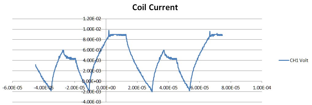
Ed's real measured current trace at 10 rev/sec:
My simulator at 10 rev/sec for a comparable motor/driver system:
BOOM.
Another noteworthy improvement is that this new version works at much higher speeds, ie it doesn't crap out when you get into voltage-limited mode and start sliding down the torque/RPM curve. I need to do some more work on refining the back-emf calcs when that happens though. Right now, you have to manually set the load angle through trial and error. I may have to switch to circular calculation mode to fix that. (Enormous performance hit.) Will keep working on it.
Ryan Carlyle
Aug 7, 2015, 11:52:03 AM8/7/15
to 3DP Ideas
Surprising finding -- Kysan 1124187 0.9 degree steppers generate 0.021 vrms/rpm. I figured they'd be twice as high since they have twice as many rotor poles. Guess not.
Ryan Carlyle
Aug 7, 2015, 5:54:46 PM8/7/15
to 3DP Ideas
So, I bought a cheap inductance meter (ok, $60 DMM with inductance mode) and I'm trying to measure some motor coils. Checking three Kysan 1124187s (nominal 6.5 mH):
Motor 1
- -2.3 mH (?????)
- 7.1 mH
Motor 2
- 2.9 mH
- 4.7
Motor 3
- 3.0 mH
- 6.5 mH
Then I remembered, stepper coil inductance is a function of rotor position. Turn the shaft and the inductance changes wildly. Interestingly, I can feel the rotor faintly buzzing in some positions (presumably due to the meter putting some signal frequency through the coil). When the rotor is held in a position where it does NOT buzz, I get consistent 6.7-7.4 mH readings across the six coils. So, that's weird. I'm curious if energizing one coil and measuring the other might be a viable strategy for a more repeatable procedure than "turn gently until the buzzing stops."
Ryan Carlyle
Aug 29, 2015, 10:43:45 PM8/29/15
to 3DP Ideas
First sheet is released, more will follow: https://github.com/rcarlyle/StepperSim
Ryan Carlyle
Sep 17, 2015, 10:09:15 AM9/17/15
to 3DP Ideas
On Saturday, August 29, 2015 at 9:43:45 PM UTC-5, Ryan Carlyle wrote:
First sheet is released, more will follow: https://github.com/rcarlyle/StepperSim
The DRV8825 sheet is also up now. Probably won't take much longer to get the THB6128 sheet done, really just have to find a few spare hours to wrap it up.
The new versions on Github have the following changes from the simulator output shown above in this thread:
- Added usage instructions!
- Added back-emf as a sine function of rotor position. This makes a HUGE difference at high speeds. Doesn't matter at low speeds.
- Added a load angle input, so you can see how the current profile changes when the motor is applying torque. (This isn't real useful at the moment, but it's there.)
- Added a coil inductor lag goal-seek function, which is necessary for back-emf to be accurate at high speeds.
- Switched FET losses to a resistance RDS(on), but left the semiconductor voltage drop field in for people who want to add braking diodes.
- Calculation methodoology is a lot more flexible and compact/dynamic in terms of spreadsheet rows required per length of time to simulate. Each row now contains one calculation tick (eg one PWM blanking time phase) of any type, and also calculates the time for the next tick to start. This is a big execution speed improvement on my old method, which required a separate row of equations to do each type of PWM behavior. (So you'd have a minimum of several rows for each PWM chopper period, even if they weren't required.)
- A new calculation tick is created any time the microstep advances, which fixed some minor errors the old simulator had when microsteps changed within an on-phase.
- There is now a minimum calculation timestep resolution which is auto-calculated based on a few parameters like motor time constant and chopper frequency. This improves the chart display quality and improves accuracy for things like back-emf changing within a long on-phase at high speeds. (Does add a ton of calculation rows though unfortunately.)
Reply all
Reply to author
Forward
0 new messages