Water cooling interfaces
306 views
Skip to first unread message

Ryan Carlyle
Jan 11, 2015, 1:49:19 PM1/11/15
to
I'm going to put a water cooling rig in my R2x at some point here. My main challenge is how to interface the cooling loop to the thermal barrier / cooling bar with a minimum of trouble. If I were designing parts like this from scratch professionally, I would drill a flow port through the length of the cooling bar and tap NPT threads or whatever at the ends to attach fittings. (I might still do that.) But my machining options at home are basically non-existent so I'm looking for easier options.
One thing I'm considering is sticking 6mm copper tubing into the heater pocket of a hot block. That would provide M6 threads for a thermal barrier and give nice heat transfer from the aluminum block to the water, but it raises some challenges with mounting. Plus this concept has some thread length shortcomings -- you really want a long M6 thread to get enough heat out of the low-conductivity steel thermal barrier.
So now I'm looking at the E3D volcano hot block, which has the M6 thread oriented the "long way" through the block, parallel to the heater pocket. Lots of threads for good thermal contact. Plus it has some "extra" M3 fixings points that I could potentially use for mounting to a new carriage bracket or something.
Normally I would just print up a plastic interface adapter to mount the parts on the carriage, but that won't hold up well in a heated chamber... So I either fight warp-tastic polycarbonate for days, or figure out something else.
I'm still thinking about options.

Chris P
Jan 16, 2015, 11:51:09 PM1/16/15
to 3dp-...@googlegroups.com
A local machine shop should be able to modify your existing cooling bar, or machine a new one with the changes you want, for $100 or so I'd think? It's a pretty simple part right? (Not real familiar with MBI extruders though)
I'd think you could get a reasonably accurate hole with a drill press and hand tap if you wanted to DIY.
Ryan Carlyle
Jan 17, 2015, 12:26:42 AM1/17/15
to 3dp-...@googlegroups.com
Man, I could do anything if I sub it out to a machine shop. I could probably dredge up a half dozen professional contacts who would do it for free as a "demo piece" to try to get some real business from my company. (Ain't no money like oilfield money. The amount my department spends on fabbing miscellaneous components completely below the radar would make you small business guys cry. It's just gross.)
But one of my goals with anything I design is making it accessible to other people to build. That's the real point of doing it with off-the-shelf parts. Post the design and BOM on Thingiverse and let other people improve on it.
Anyway, right now I'm leaning towards using a threaded dual cooling bar (eg Carl's) and M6-by-hose-barb fittings in the left extruder slot. Aluminum's conductivity is so high that a few square centimeters of cross-section is functionally zero resistance to heat flux. So cooling through the left extruder slot's thermal barrier tube threads should also cool the right extruder thermal barrier with high efficiency.
The challenge there, of course, is routing the tubing so it doesn't hang below the primary nozzle. McMaster doesn't have a lot of M6 fittings so finding an appropriate elbow is looking to be painful.

Dan Newman
Jan 17, 2015, 12:47:50 AM1/17/15
to 3dp-...@googlegroups.com
> Anyway, right now I'm leaning towards using a threaded dual cooling bar (eg
> Carl's) and M6-by-hose-barb fittings in the left extruder slot. Aluminum's
> conductivity is so high that a few square centimeters of cross-section is
> functionally zero resistance to heat flux. So cooling through the left
> extruder slot's thermal barrier tube threads should also cool the right
> extruder thermal barrier with high efficiency.
> The challenge there, of course, is routing the tubing so it doesn't hang
> below the primary nozzle. McMaster doesn't have a lot of M6 fittings so
> finding an appropriate elbow is looking to be painful.
You canreadily source soft copper refrigeration tubing in 1/8 and 3/16" ODs.
(Problem is, you end up with 10 feet of the stuff.) Sweat soldering it onto
a brass fitting is fairly straight forward (as long as you flux it first).
You do have to be careful bending it in a tight radius: even soft copper
tubing will happily collapse on the bend if you aren't careful.
I'm not sure if the above qualifies as simple enough for lay people to do.
Doesn't require a machine shop, but does require a cheap ass torch, flux,
and some plumbing solder. You could dispense with the soldering if you
went the flare fitting route with a flaring tool, but that's going to be
a larger fitting overall.
And then there's things like this,
http://www.ebay.com/itm/like/260448592717?lpid=82&chn=ps
Festo makes lots of those as well (QS, Quick Star line).
Dan
Ryan Carlyle
Jan 17, 2015, 1:09:34 AM1/17/15
to 3dp-...@googlegroups.com
I have some 6mm copper tubing that I've been playing with, since 6mm is the standard heater size and coincidentally the diameter thermal tube the stock R2x cooling bar is designed for. The nominal MBR is pretty large, but for low-pressure service at low flow rates it'd probably be good for pretty dang tight turns.
Here are my two leading contenders at the moment. The R2x bar is really appealing because it's ridiculously easy. Not sure if there's enough cross-section for heat flux through the clamp though.
E3D Volcano hot blocks:

Stock R2x cooling bar:

Ryan Carlyle
Jan 17, 2015, 1:12:02 AM1/17/15
to 3dp-...@googlegroups.com
Incidentally, that's some super-soft soft silicone tubing to run through the extruder flex loop. It's so soft you almost can't get a good seal on the copper tube though. Proper metal hose clamps cut through the tube. So it's probably going to be five zipties and careful leak monitoring.

scott.e...@gmail.com
Jan 17, 2015, 8:53:10 AM1/17/15
to 3dp-...@googlegroups.com
Back in my Nitro RC days I used to make compression ferrules by tweaking the ID of thin walled aluminum or brass tubing and creating a generous lead-in chamfer. You could probably even print one.
Ryan Carlyle
Jan 17, 2015, 8:10:21 PM1/17/15
to 3dp-...@googlegroups.com
The R2x stock cooling bar option was so easy I couldn't help but try it out. It's about an hour into a heat soak / leak test right now.
- Left extruder: 230C (preheat only, not printing)
- Ambient: 23C
- Water reservoir: 28C
- Cooling bar, measured adjacent to copper tube: 31C
1" bend diameter jig I made, because for some crazy reason I don't have any 6mm tube-benders on hand:

R2x hot end:


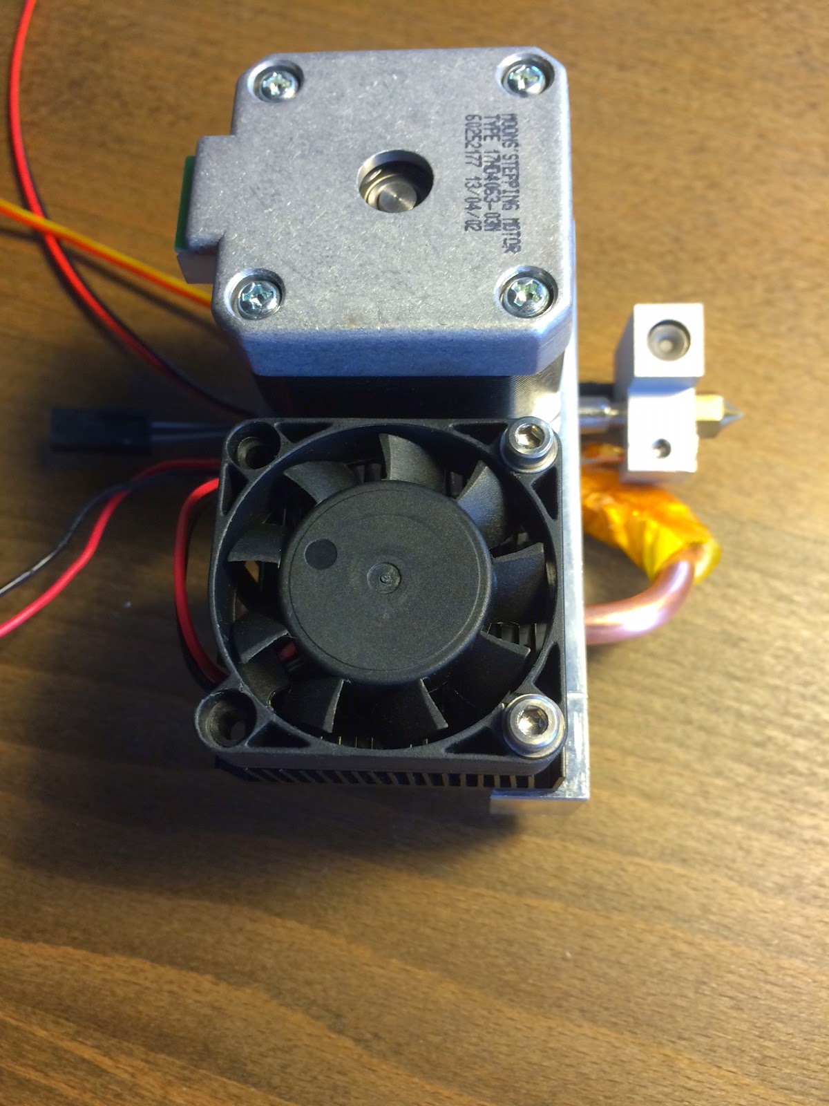
The heatsink/fan on the back side is an "emergency backup" cooler in case my crummy $25 water pump goes out. It's hooked to the right extruder slot, which is sensing cooling bar temp. More importantly though, the heatsink hits the X endstop switch so I can home it without having the right extruder installed.
You might also note that this is one of Carl's magic "built-in thermocouple" heater cartridges. I'm going to do some experiments with that later, but it's disconnected for now. Hot block temp is coming from a normal "twisted tip wrapped in Kapton" termination.
Full test setup. You may notice the lack of any kind of radiator. It seems to be totally unnecessary.

Honestly, the hardest part was figuring out how to connect all the mismatched parts I bought. None of the hoses or fittings match size anywhere in the rig. But silicone tubing is pretty forgiving.
Ryan Carlyle
Jan 17, 2015, 10:50:00 PM1/17/15
to 3dp-...@googlegroups.com
Got the printer running test prints. I did find a very minor leak at the copper/silicone interface. I threw more zip-ties at the problem -- hopefully it goes away.

I'm overdue for some serious wiring cleanup, of course.
Dan Newman
Jan 17, 2015, 11:00:01 PM1/17/15
to Ryan Carlyle, 3dp-...@googlegroups.com
On 17/01/2015 7:50 PM, Ryan Carlyle wrote:
> Got the printer running test prints. I did find a very minor leak at the
> copper/silicone interface. I threw more zip-ties at the problem --
> hopefully it goes away.
>
> <https://lh4.googleusercontent.com/-fEpxKZDJ4N4/VLstUZs3S4I/AAAAAAAABDs/kPztiEFJ2pw/s1600/IMG_1092.JPG>
> Got the printer running test prints. I did find a very minor leak at the
> copper/silicone interface. I threw more zip-ties at the problem --
> hopefully it goes away.
>
> I'm overdue for some serious wiring cleanup, of course.
Where's the drip pan?
Dan
Ryan Carlyle
Jan 18, 2015, 12:31:41 AM1/18/15
to 3dp-...@googlegroups.com
I started with one, but it interfered with my hose routing. I know, very irresponsible of me.
In my defense, I ran the water loop in my sink for about 3 hours with no visible leaks before transplanting it intact to the printer.

Jetguy
Jan 18, 2015, 7:09:18 AM1/18/15
to 3dp-...@googlegroups.com
Just use purified bottled water and a complete non-issue (well rust, but anyway) because if it's pure water, no conduction of electricity.
Good way to really cool the printed layers. None of this "air cooling" junk.
Ryan Carlyle
Jan 18, 2015, 10:11:56 AM1/18/15
to 3dp-...@googlegroups.com
Hmm, I wonder what the resistivity of distilled water would be after circulating through aluminum and copper components for a few weeks. I'm sure it's picking up some stray ions, but I don't know how much difference it makes.

adam paul
Jan 18, 2015, 10:29:22 PM1/18/15
to 3dp-...@googlegroups.com
Just for my own remedial knowledge. Why cant you replace the 40x40 fan and heatsink with a water block?
Ryan Carlyle
Jan 18, 2015, 11:10:34 PM1/18/15
to 3dp-...@googlegroups.com
On Sunday, January 18, 2015 at 9:29:22 PM UTC-6, adam paul wrote:
Just for my own remedial knowledge. Why cant you replace the 40x40 fan and heatsink with a water block?
You can if you can figure out a way to mount it on there. I couldn't come up with any easy way to adapt an off-the-shelf water block to the 40mm fan bolt spacing. And you can't exactly drill holes through a water block like you can with a heat sink :-)
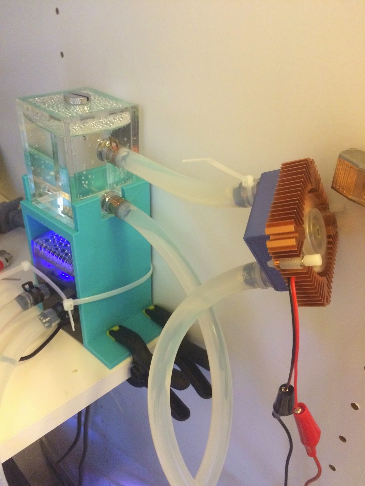
Incidentally, I'm 1h33m into a watercooled ABS print right now. I did a long preheat and a couple quick prints before that. Everything is performing well. System temps:
- Hot end: 230C
- HBP: 95C
- Chamber: 43C at nozzle height
- Cooling bar: 56C adjacent to thermal barrier clamp
- Water loop: 39C
I think I'm going to need to add a radiator to the water loop after all. That's more temp rise than I was expecting. The silicone hose and acrylic reservoir don't shed heat well.

Gary Crowell
Jan 19, 2015, 4:59:19 AM1/19/15
to 3dp-...@googlegroups.com
Hmmm, something like...
--
You received this message because you are subscribed to the Google Groups "3DP Ideas" group.
To unsubscribe from this group and stop receiving emails from it, send an email to 3dp-ideas+...@googlegroups.com.
To post to this group, send email to 3dp-...@googlegroups.com.
To view this discussion on the web visit https://groups.google.com/d/msgid/3dp-ideas/16a142c7-083c-4d65-bb3a-e90c9a0f964a%40googlegroups.com.
Ryan Carlyle
Jan 19, 2015, 3:55:49 PM1/19/15
to 3dp-...@googlegroups.com
I think if you're going to fabricate something complicated, it makes way more sense to cut the flow port through a custom cooling bar. You don't actually need much surface area if you make a direct water/aluminum interface. It's the steel-aluminum and aluminum-aluminum interfaces that have all the resistance to heat flux.

Brandon Pomeroy
Jan 19, 2015, 7:49:46 PM1/19/15
to 3dp-...@googlegroups.com
So why didn't you just cut the flow port through your cooling bar? Admittedly there's not a lot of places that you can slice away, but you could drill a channel straight through the center (See red dot):

It's not a whole lot of surface area, but it's about the same amount that you've got in your original design. It would also allow you to use both extruders.
Issues you'd run into are interference with the water pipe and the fan heasinks (But those heatsinks may go away if you can cool fast enough), and interference on the back side, between the motors. Some creative routing could fix that, though (In the front, out the top?).
This also would only require a drill press (Or a hand drill if you're careful), since the width of the block is so small.
adam paul
Jan 19, 2015, 8:01:09 PM1/19/15
to 3dp-...@googlegroups.com
Anywhere other then Carl to get a rep 2x cooling bar?
Ryan Carlyle
Jan 19, 2015, 11:13:43 PM1/19/15
to 3dp-...@googlegroups.com
It occurred to me last night that if you're going to give up an extruder, you can just clamp a water block to the flat top surface of the cooling bar. The R2x carriage (and Carl's version) has gaps on either side of the bar slot where tie bolts could go. Or you could just tap some new M3 threads into a blank section. So that's easier and maybe more effective than the copper tube option.
Brandon -- the problem with drilling the center is how much space the steppers take up on the back side, versus the footprint you'd need for a fitting. You might be able to fit something like a 1/8" NPT (grease zerk size fitting) but even then you might need to drill through at a weird angle.
Adam -- the stock R2x style bar is only made by Makerbot, to my knowledge. Carl's bar is M6 threaded. So you could screw in brass M6 pipe thread fittings if there's enough real estate below the bar.
Brandon Pomeroy
Jan 20, 2015, 3:16:39 AM1/20/15
to 3dp-...@googlegroups.com
the problem with drilling the center is how much space the steppers take up on the back side, versus the footprint you'd need for a fitting. You might be able to fit something like a 1/8" NPT (grease zerk size fitting) but even then you might need to drill through at a weird angle.
Mm, yeah, I see what you mean. And (now looking at an assembled extruder), there wouldn't even be room to route it out of the top of the assembly.
Let's go back to the "water block replacing the fan assembly" idea. Gary made a pretty complex water block a few posts back, but what about a simpler one? Something like the Kraken, from e3D: Take a 40x40x20 block of aluminum, drill a channel through the sides, plug up those holes with teflon-lined set screws, then drill some blind holes into that channel for the input/output. Toss a couple M3 holes in the corners at the same spacing as the fan mount, and there you go.
The only downside to that is having to procure a chunk of metal that's the right size, but it's not too hard to get custom cut aluminum billets, even online.
adam paul
Jan 20, 2015, 12:22:43 PM1/20/15
to 3dp-...@googlegroups.com
Is laser cutting an acceptable maker machine tool? Could you take Gary's 40x40 waterblock, slice it, laser cut it, stack it back up on a 40x60mm plate to mount with extruder motor and have a pretty tidy water block.
Gary Crowell
Jan 20, 2015, 2:17:38 PM1/20/15
to 3dp-...@googlegroups.com
I don't have the CNC to cut a nice water block either (tho I might dig something up). Was also thinking it might be something I could mill manually, but that could get ugly.
I totally agree that the cold bar is the right place for water cooling, I'm just looking for something bolt-on.
--
You received this message because you are subscribed to the Google Groups "3DP Ideas" group.
To unsubscribe from this group and stop receiving emails from it, send an email to 3dp-ideas+...@googlegroups.com.
To post to this group, send email to 3dp-...@googlegroups.com.
To view this discussion on the web visit https://groups.google.com/d/msgid/3dp-ideas/5d815522-bf5d-43bf-aece-779f27073f2a%40googlegroups.com.
Ryan Carlyle
Jan 20, 2015, 3:58:21 PM1/20/15
to 3dp-...@googlegroups.com
My original cooling plan was actually peltiers to supplement the fans. (And help heat the chamber.) Then all you have to do is take a ~3mm sheet of aluminum, cut it to ~40x50mm, and drill two holes at the bottom to bolt it to the cooling bar. That adapter plate would just act as a heat spreader between the cooling bar and peltier chip.
Of course, it's important to note that peltiers only work if you keep the "hot side" cooled effectively. If your hot-side fan goes out, they'll roast the cooling bar. And their efficiency and cooling capacity is quite low. I'm not sure if a 50W peltier can keep up with all the heat from the hot end, stepper, and convection from chamber heat to the carriage/bar.
To unsubscribe from this group and stop receiving emails from it, send an email to 3dp-ideas+unsubscribe@googlegroups.com.
To view this discussion on the web visit https://groups.google.com/d/msgid/3dp-ideas/5d815522-bf5d-43bf-aece-779f27073f2a%40googlegroups.com.
Ryan Carlyle
Jan 20, 2015, 5:47:28 PM1/20/15
to 3dp-...@googlegroups.com
I added a little cooler unit because I had the parts and it was easy. It dropped the equilibrium water temp by 2-3C. Not exactly a rousing success, but it also dropped the cooling bar by 2C or thereabouts.
Brandon Pomeroy
Apr 21, 2015, 12:47:09 AM4/21/15
to 3dp-...@googlegroups.com
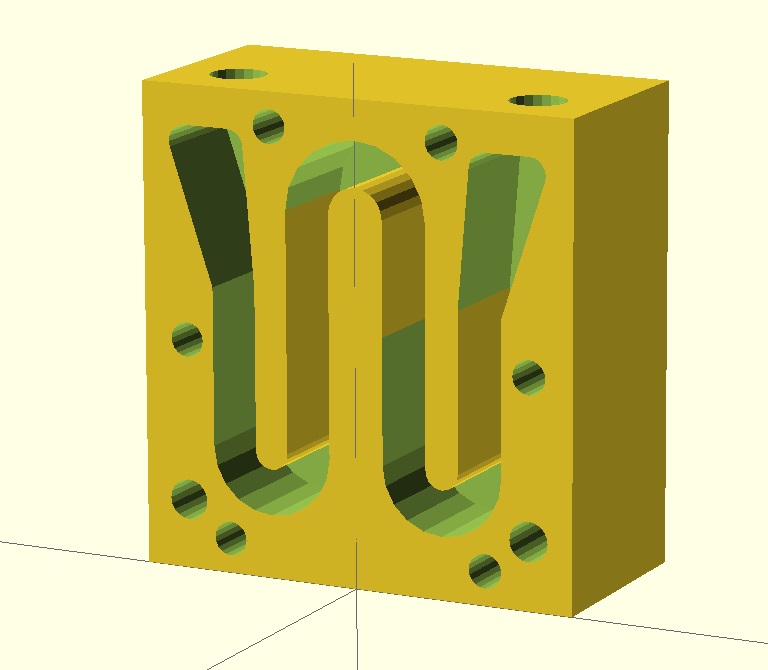
Bringing this up again because my current printer design will use water cooling. Initially I was going with a Bowden style with a custom machined bar mount, but I've since moved back to direct drive. Since I'm lazy, and would prefer to be able to order all of my hot end parts off of Robotdigg, I whipped up a water cooling block that should be able to work just fine on stock MK7 hotends.
Here's the block itself: http://i.imgur.com/1WgWPRl.png
Here's a section view showing the channel for the water: http://i.imgur.com/WY4qM8e.png
And here it is actually attached to a dual MK7: http://i.imgur.com/k1o5HyN.png
The block is a 1.5in x 1.5in x 30mm billet of aluminum. Stupid mixing of units, I know... But I'm in the States, and getting metric bars is much more difficult than it should be. This particular size can be had from OnlineMetals for around 5 bucks, cut to size. Past that, it just takes a few minutes on a drill press to have the block ready to go.
I've got the aluminum on order now, and hope to have one in place and testing on a Rep 2 by the end of the week.
To unsubscribe from this group and stop receiving emails from it, send an email to 3dp-ideas+...@googlegroups.com.
To view this discussion on the web visit https://groups.google.com/d/msgid/3dp-ideas/5d815522-bf5d-43bf-aece-779f27073f2a%40googlegroups.com.
Ryan Carlyle
Apr 21, 2015, 11:54:41 AM4/21/15
to 3dp-...@googlegroups.com
Cool. Do you think it could be made thinner without losing too much strength? Looks like it's thicker/heavier than it needs to be.
What kind of threads are you planning on tapping for the side-port plugs and the hose fittings?
I tabled the watercooling experiments to print polycarbonate on my R2x for a while. It prints fine with air cooling in a heated chamber, unlike other filaments. But I've been thinking about switching back to an ABS+HIPS rig for some stuff, and watercooling would be nice for that.
Brandon Pomeroy
Apr 21, 2015, 12:21:17 PM4/21/15
to 3dp-...@googlegroups.com
It could easily be made thinner, but as it is, it is a drop-in replacement for the current fan/heatsink assembly. The bolt store is just down the street, but it's nice to be able to just use standard hardware.
The holes I have modeled are meant for 6mm, but could easily be larger or smaller... Whatever you have on hand, really.
Ryan Carlyle
Apr 21, 2015, 3:03:53 PM4/21/15
to 3dp-...@googlegroups.com
Yeah, I hate to admit it, but for little stuff like this, I'm partial to 1/4" NPT.
Brandon Pomeroy
Apr 21, 2015, 3:30:17 PM4/21/15
to 3dp-...@googlegroups.com
Considering that's the size of nozzle and threading I have on hand, I think there's no shame in using it! Trying to get metric fittings in the US is ridiculous...

Petr Ptacek
Apr 22, 2015, 12:55:42 AM4/22/15
to 3dp-...@googlegroups.com
I agree. Here in states, I do everything imperial except motion axis. You can save ton of money this way.
Anyway, to your water block. I really like the idea of using just drill to create fluid channel, but I would advise to use copper block instead of aluminium.
Pretty much every nozzle available is brass and I would worry about galvanic corrosion. Yes, you can add inhibitors, but is it really worth the risk?
Ryan Carlyle
Apr 22, 2015, 8:25:41 AM4/22/15
to 3dp-...@googlegroups.com
You thinking of hose barbs? The extruder nozzle shouldn't be an issue because it's not wetted.
Petr Ptacek
Apr 22, 2015, 9:44:51 AM4/22/15
to 3dp-...@googlegroups.com
Yes, hose barbs. Also one have to think about radiator. I tried in the past to use big reservoar for my CNC spindle and it was not very practical. Temperature was steadilly climbing. So for 10+ hour prints I would say radiator is a must. One more component to be compatible. So I say go all copper or all aluminum, but plan ahead.
Ryan Carlyle
Apr 22, 2015, 1:22:03 PM4/22/15
to 3dp-...@googlegroups.com
Agreed... I think all-aluminum blocks/radiators with plastic hose fittings is probably the way to go for this kind of service. The oxide passivation film helps a lot.
Also gotta remember biocide. Chemicals are ok, but silver kill coils seem a lot nicer. Off the top of my head, mixing silver and copper or brass is a bad idea. Plastic hose fittings for low pressure service are pretty easy to get in imperial sizes from McMaster. The water loop should keep them from getting too weak in the heated chamber.
Raises a good question though. What's the reliability of a watercooling loop relative to a brushless DC fan? Should we be aiming for two separate loop systems (one for each extruder) or maybe install a cold-end thermal fuse to kill extruder heater power if the watercooling fails?
Brandon Pomeroy
Apr 22, 2015, 3:56:11 PM4/22/15
to 3dp-...@googlegroups.com
I use this radiator:
Which has aluminum barbs. Not sure if the internal water pipe is copper or aluminum, though... But regardless, I'm not concerned about corrosion. The amount of heat needed to be dissipated from a hot end is laughably low compared to computer components, so even with heat transfer restricted by the formation of oxides, I'm fairly certain that the block will stay nice and cool.
Also not concerned with biocide for now... simply because this particular block is just a test fixture to verify my guess that this can replace the fan. If that's confirmed, I can remake the block using either a better drill press or a mill.
I am, however, concerned about the loop failure, like Ryan mentioned. I've been meaning to look into Sailfish to see how bad it would be to add in an extra thermistor to monitor the cold end, and pause the print if it gets too hot. Though, now that I'm typing it out, it might make more sense to have a small, standalone board that just sends a signal to the P-STOP...
Ryan Carlyle
Apr 22, 2015, 6:57:19 PM4/22/15
to 3dp-...@googlegroups.com
What I did for my testing was remove an extruder, stick its thermocouple in an unused bolt hole on the cooling bar, and use shorter bolts to attach a regular heatsink/fan arrangement to the unused extruder slot. Then you can set the fan turn-on temp to your desired cold end "safety temp" as a backup cooling device.
Aside from that, I think a ~100C thermal fuse kapton-taped to the cooling bar and wired in series with the extruder heater is probably the way to go. I've been thinking about doing that for my regular air-cooled hot ends too.
Then there's the passive option. If you have nice thin heat breaks and not the mk10 PTFE-lined monsters, you can probably just let the cooling loop water boil and siphon-fill for hours if you arrange the water loop right.
Brandon Pomeroy
Apr 22, 2015, 9:38:12 PM4/22/15
to 3dp-...@googlegroups.com
Are thermal fuses resettable, though? It'd be pretty annoying to have to replace a component each time something like that happened.
As an aside, I have my water loop hooked up now. I'm going to run it all night to check for leaks, but I should have some data on the temperatures by tomorrow evening.
Ryan Carlyle
Apr 22, 2015, 9:59:47 PM4/22/15
to 3dp-...@googlegroups.com
You can buy auto-reset thermal fuses, but I don't think you'd want that. It's an emergency protective device that you want to totally stop all heater action. Having it continuously turn the heater on and off like a bad thermostat is probably not the desired behavior if the cooling system fails. (Hopefully this is just insurance, not something that gets used a lot...)
Petr Ptacek
Apr 23, 2015, 6:18:51 PM4/23/15
to 3dp-...@googlegroups.com
Agree. One shot fuses are cheap, and likelihood of your loop failing is actually pretty low.
Anyway, I personally use something similar to this (http://www.aliexpress.com/item/G1-Inch-Water-Flow-Sensors-Hall-Effect-Sensor-Switch-Flow-Meter-Counter-1-60L-min-Flow/1975084874.html)
to protect my $500 spindle. It works like fan with tachometer. I have it wired to the little arduino nano and it operates like NC switch in series with e-stop and limit switches. Hour worth of work and <$20. Not sure if it worth it for 3d printer though. fuse seems to be simpler solution.
And Brandon, I would worry about corrosion. Look up some cases from computer liquid cooling. It is not about temperature, but about flow, liquid you use, micro surface of the metals used in the loop etc. It is much more complicated, then it looks. I would never ever mix alu with copper in one loop, no matter what. I twill fails, it is just matter of time. It can completely clog your loop under 24 hours in certain conditions due to runaway effect.
Brandon Pomeroy
Apr 23, 2015, 6:23:07 PM4/23/15
to 3dp-...@googlegroups.com
I guess the problem I see with a thermal fuse inline with the extruder (As opposed to a separate board that triggers a P-Stop) is that in the event of a water cooling failure, I'd want the entire machine to shut down. A thermal fuse works alright for a Rep2 style bot (1 heating element), but what if you have a machine with two extruders and heated bed? You could have a fuse on each extruder wire, but then if they trip, you have your bed heating your print and wasting energy. Not to mention the fact that there'd be no visual indication of failure (If you were across the room, it would look like your printer was continuing as normal)
It seems like it'd make more sense to have a thermal fuse that cuts power to the machine completely... but then you have an awkwardly thick wire running to your extruder carriage, and you'd have to be really careful about flexing.
Brandon Pomeroy
Apr 23, 2015, 6:52:19 PM4/23/15
to 3dp-...@googlegroups.com
Petr- I would argue that it is all about temperature. Your flow and liquid affect the temperature, but as long as the temperature of the loop is where it needs to be, your water cooling is working fine.
That being said, it is definitely easier to simply avoid corrosion rather than work around it. I'll probably move to plastic connectors on the next iteration. I just happened to have brass ones on hand.
Petr Ptacek
Apr 23, 2015, 6:59:38 PM4/23/15
to 3dp-...@googlegroups.com
I would wire themal fuse as another NC switch in series with limit switches (and e-stop if you have one). This will stop everything.
Ryan Carlyle
Apr 23, 2015, 7:05:30 PM4/23/15
to 3dp-...@googlegroups.com
On Thursday, April 23, 2015 at 5:23:07 PM UTC-5, Brandon Pomeroy wrote:
I guess the problem I see with a thermal fuse inline with the extruder (As opposed to a separate board that triggers a P-Stop) is that in the event of a water cooling failure, I'd want the entire machine to shut down. A thermal fuse works alright for a Rep2 style bot (1 heating element), but what if you have a machine with two extruders and heated bed? You could have a fuse on each extruder wire, but then if they trip, you have your bed heating your print and wasting energy. Not to mention the fact that there'd be no visual indication of failure (If you were across the room, it would look like your printer was continuing as normal)It seems like it'd make more sense to have a thermal fuse that cuts power to the machine completely... but then you have an awkwardly thick wire running to your extruder carriage, and you'd have to be really careful about flexing.
I install filament monitors on all my Mightyboard printers anyway. (It's kind of mandatory when you do as much goofy unreliable stuff as I do.) If the fuse pops, the hot end cools, the filament stalls, and a P-stop is triggered rather quickly. That pauses the print and starts cooling everything.
Brandon Pomeroy
Apr 23, 2015, 8:06:23 PM4/23/15
to 3dp-...@googlegroups.com
All good points... I had forgotten about the filament monitor! I'll probably have to pick a few up for more printer anyways...
On a related note, this is what I did today:
Unfortunately, my data logging program crashed... so my ~2 hours of temperature data didn't even save! But here's a quick overview of testing I did:
(All numbers are in seconds)
- 0 - turned machine on
- 125 - loaded filament
- 460 - motor timed out from loading filament
- 480 - preheat started (230C)
- 1430 - print started (15 minutes of preheat)
- 3880 - print finished
- 3900 - preheat started (230C)
- 7713 - preheat turned off
My thermistor was taped to the surface of the bar mount (Not the water cooling block), and the temperature hovered around 31C during loading, preheating, and printing. The temperature never went above 35 C. Ideally we'd be measuring the temperature of the thermal barrier tube directly, but I'm not sure if that's possible.
Confounding factors: The hot end is not a stock MBI MK7 -- the thermal break does have a teflon lining. I don't know enough about hot end physics to know if that invalidates my test, but if it doesn't, this test implies that using a water cooled block in the same format as the stock heatsink/fan combo works just fine.
Future work: Testing on a stock MBI thermal barrier tube should be done. A redesign of the cooling block is necessary as well, since the vertical nozzle block some Y-motion, and requires you to replace the component that holds the blower and electronics bundle. If anyone knows of low profile barbs, let me know!
Ryan Carlyle
Apr 23, 2015, 8:11:50 PM4/23/15
to 3dp-...@googlegroups.com
Hmm, 31C sounds good to me. Typically, the PTFE-lined hot ends have more cross-section through the heat break than genuine Rep2 thermal barriers, so I think it would get better with the all-metal thermal barrier, not worse.
Reply all
Reply to author
Forward
0 new messages