Jaluino next version: what could be added/improved

Sebastien Lelong
Since last try to build Jaluino v1.0 (http://jallib.blogspot.com/2009/08/building-jaluino-v10.html), I've been thinking a lot about what could be improved and added. Here's a list of point I think it can be nice to have, though I understand not all may be doable in a homebrew version. Anyway they will be here as a reminder...
- I²C: current version isn't I²C enabled. That would be really great to have this. There are different options I can think, depending on how the PCB can get complex:
1. Two resistors, with jumpers to select whether you want to i2c enabled or not, and a connector (see Joep suggestion: http://groups.google.com/group/jallib/msg/2042aeffaba02b33?hl=en). SDA/SCL are exposed through shield connectors.
2. Two resistors, with jumpers to select whether you want to i2c enabled or not. No connector, SDA/SCL still usable via connectors.
3. Two resistors. Either you solder them, either not, whether you want I2C or not (but switching master/slave will be a pain...)
4. Last option, two resistors to solder or not, and the i2c connector.
- Being able to use 3.3V power source. I know it adds another part and use lots of precious space, but it might possible since there are some space at the bottom. Should 3.3V be produced by jack power, USB or serial source, or just jack and USB ?
- last point, and the most important IMO, increase the space between upper and bottom shield connectors. Using your measurement file, this is "16 pitch = 40.64 mm" (note I measure ~40.18mm, am I wrong ?). I think it's way too narrow, because you can't even put a mini-breadboard between them. As you said in a previous mail, if we want to have this intermediate shield, distance has to be different from Arduino (or the shield will be hard to create). What do you think about a distance a little bit bigger than Arduino. For Arduino, I measure ~49mm, what about something like 55mm ? Power connector on the left can remain uncentered IMO.
I wish I could help with the PCB, like moving these connectors, but I don't have Orcad and don't know how to use it (I may give a try with the demo version if it's not too limited).
Cheers,
Seb
--
Sébastien Lelong
http://www.sirloon.net
http://sirbot.org

vasile surducan
Hi guys, hi Richard,
Since last try to build Jaluino v1.0 (http://jallib.blogspot.com/2009/08/building-jaluino-v10.html), I've been thinking a lot about what could be improved and added. Here's a list of point I think it can be nice to have, though I understand not all may be doable in a homebrew version. Anyway they will be here as a reminder...
- I²C: current version isn't I²C enabled. That would be really great to have this. There are different options I can think, depending on how the PCB can get complex:
1. Two resistors, with jumpers to select whether you want to i2c enabled or not, and a connector (see Joep suggestion: http://groups.google.com/group/jallib/msg/2042aeffaba02b33?hl=en). SDA/SCL are exposed through shield connectors.
2. Two resistors, with jumpers to select whether you want to i2c enabled or not. No connector, SDA/SCL still usable via connectors.
3. Two resistors. Either you solder them, either not, whether you want I2C or not (but switching master/slave will be a pain...)
4. Last option, two resistors to solder or not, and the i2c connector.
- Being able to use 3.3V power source. I know it adds another part and use lots of precious space, but it might possible since there are some space at the bottom. Should 3.3V be produced by jack power, USB or serial source, or just jack and USB ?
- last point, and the most important IMO, increase the space between upper and bottom shield connectors. Using your measurement file, this is "16 pitch = 40.64 mm" (note I measure ~40.18mm, am I wrong ?). I think it's way too narrow, because you can't even put a mini-breadboard between them. As you said in a previous mail, if we want to have this intermediate shield, distance has to be different from Arduino (or the shield will be hard to create). What do you think about a distance a little bit bigger than Arduino. For Arduino, I measure ~49mm, what about something like 55mm ? Power connector on the left can remain uncentered IMO.
I wish I could help with the PCB, like moving these connectors, but I don't have Orcad and don't know how to use it (I may give a try with the demo version if it's not too limited).

Richard
> Hi guys, hi Richard,
>
> Since last try to build Jaluino v1.0 (http://jallib.blogspot.com/2009/08/building-jaluino-v10.html), I've been
> thinking a lot about what could be improved and added. Here's a list of
> point I think it can be nice to have, though I understand not all may be
> doable in a homebrew version. Anyway they will be here as a reminder...
>
> - I²C: current version isn't I²C enabled. That would be really great to
> have this. There are different options I can think, depending on how the PCB
> can get complex:
>
> 1. Two resistors, with jumpers to select whether you want to i2c enabled
> or not, and a connector (see Joep suggestion:http://groups.google.com/group/jallib/msg/2042aeffaba02b33?hl=en). SDA/SCL
> are exposed through shield connectors.
>
> 2. Two resistors, with jumpers to select whether you want to i2c enabled
> or not. No connector, SDA/SCL still usable via connectors.
>
> 3. Two resistors. Either you solder them, either not, whether you want
> I2C or not (but switching master/slave will be a pain...)
>
> 4. Last option, two resistors to solder or not, and the i2c connector.
>
> - Being able to use 3.3V power source. I know it adds another part and use
> lots of precious space, but it might possible since there are some space at
> the bottom. Should 3.3V be produced by jack power, USB or serial source, or
> just jack and USB ?
>
> - last point, and the most important IMO, increase the space between upper
> and bottom shield connectors. Using your measurement file, this is "16 pitch
or a small slip off the drill :-)
> I think it's way too
> narrow, because you can't even put a mini-breadboard between them. As you
> said in a previous mail, if we want to have this intermediate shield,
> distance has to be different from Arduino (or the shield will be hard to
> create). What do you think about a distance a little bit bigger than
> Arduino. For Arduino, I measure ~49mm, what about something like 55mm ?
> Power connector on the left can remain uncentered IMO.
>
> I wish I could help with the PCB, like moving these connectors, but I don't
> have Orcad and don't know how to use it (I may give a try with the demo
1 distance is now 55,88mm (22 pitch)
2 add i2c plus connector like Joeps idea but without the Vin
I hope you are not to attached to the via’s (wire bridges), because I
managed to remove one, so only 2 left ;-).
3.3V will be added as soon as i know wat you want with it,.
you can find the files in de file section, please check so i can
change together with adding 3.3V power option (hopefully without to
many via’s)
Greetz
Richard
Sebastien Lelong
Do you mean selection between 5V and 3.3V or add 3.3V ?
> - Being able to use 3.3V power source. I know it adds another part and use
> lots of precious space, but it might possible since there are some space at
> the bottom. Should 3.3V be produced by jack power, USB or serial source, or
> just jack and USB ?
I mean add 3.3V, so you can use part with that voltage easily (original Arduino takes 5V and 3.3V from FTDI chip). I don't know what option is the best, maybe Vasile's suggestion about a "3.3V LDO as BA033 from Rohm" is nice. I'll let you decide ;)
Yes, it should be 40.64, maybe your printer did not print exactly 1:1
>
> - last point, and the most important IMO, increase the space between upper
> and bottom shield connectors. Using your measurement file, this is "16 pitch
> 40.64 mm" (note I measure ~40.18mm, am I wrong ?).
or a small slip off the drill :-)
My mistake, I measured wrong...
Thank you :-)
> I think it's way too
> narrow, because you can't even put a mini-breadboard between them. As you
> said in a previous mail, if we want to have this intermediate shield,
> distance has to be different from Arduino (or the shield will be hard to
> create). What do you think about a distance a little bit bigger than
> Arduino. For Arduino, I measure ~49mm, what about something like 55mm ?
> Power connector on the left can remain uncentered IMO.
don’t worry it is already finished.
>
> I wish I could help with the PCB, like moving these connectors, but I don't
> have Orcad and don't know how to use it (I may give a try with the demo
OK!
1 distance is now 55,88mm (22 pitch)
2 add i2c plus connector like Joeps idea but without the Vin
I hope you are not to attached to the via’s (wire bridges), because I
managed to remove one, so only 2 left ;-).
Awesome :)
3.3V will be added as soon as i know wat you want with it,.
OK, great
you can find the files in de file section, please check so i can
change together with adding 3.3V power option (hopefully without to
many via’s)
OK I had a look but I have few time right now so I'll check deeply later, but it looks very nice. I'm afraid I won't be able to build a new one this WE, no laser printer, and, worst, no more copper board...
Thanks for this !
Cheers,
Seb
Richard
> > Do you mean selection between 5V and 3.3V or add 3.3V ?
>
> I mean add 3.3V, so you can use part with that voltage easily (original
> Arduino takes 5V and 3.3V from FTDI chip). I don't know what option is the
> best, maybe Vasile's suggestion about a "3.3V LDO as BA033 from Rohm" is
> nice. I'll let you decide ;)
on the power connector or also go to the 18F4550 so selectable 5V or
3.3V power on the 18f4550 ?
Or maybe all the 5V on the main board (after the fuse) selectable
between 5V and 3.3V and only let 5V go to the serial connector.
>
> My mistake, I measured wrong...
>
International des Poids et Mesures in Parijs thus so close to your
home :-).
>
>
> OK I had a look but I have few time right now so I'll check deeply later,
> but it looks very nice. I'm afraid I won't be able to build a new one this
> WE, no laser printer, and, worst, no more copper board...
no changes needing anymore.
I then will finish BOM and making a new shield base
>
> Thanks for this !
You’re welcome, and thanks for the fast feedback.
Greetz
Richard

funlw65
card or other peripherals... You can have the regulator on shield but
is better (and cheaper) to have it on motherboard.
I think is enough for power connector.
Sebastien Lelong
Creating the 3.3V is no problem but should it only go to the spare pin
on the power connector or also go to the 18F4550 so selectable 5V or
3.3V power on the 18f4550 ?
Yes, let's put 3.3V on the spare pin of power connector (I think it's where it was originally designed to). As for powering 18F4550, I guess 5V is enough. I have a LF version which can go far lower than 3.3V, but it's another topic and quite advanced feature.
Or maybe all the 5V on the main board (after the fuse) selectable
between 5V and 3.3V and only let 5V go to the serial connector.
Is it complicated to do this ? Does it worth it ? Can it be postpone on a next version without much changes if it becomes very important ? And maybe some serial connectors can use 3.3V. too I guess there are many options we can't cover. For now, we can stay on 3.3V on spare pin, for shields, and let the PIC be powered with 5V
How is that possible, in paris you have the exact Meter in Bureau
> My mistake, I measured wrong...
>
International des Poids et Mesures in Parijs thus so close to your
home :-).
Yes, but probably my eyes weren't so close to my orbits...
Cheers,
Seb
Richard
On Aug 29, 10:28 am, Sebastien Lelong <sebastien.lel...@gmail.com>
wrote:
>
> Creating the 3.3V is no problem but should it only go to the spare pin
>
> > on the power connector or also go to the 18F4550 so selectable 5V or
> > 3.3V power on the 18f4550 ?
>
> Yes, let's put 3.3V on the spare pin of power connector (I think it's where
> it was originally designed to). As for powering 18F4550, I guess 5V is
> enough. I have a LF version which can go far lower than 3.3V, but it's
> another topic and quite advanced feature.
>
>
>
> > Or maybe all the 5V on the main board (after the fuse) selectable
> > between 5V and 3.3V and only let 5V go to the serial connector.
>
> Is it complicated to do this ? Does it worth it ? Can it be postpone on a
> next version without much changes if it becomes very important ? And maybe
> some serial connectors can use 3.3V. too I guess there are many options we
to keep the serial connector at 5V all the time.
> can't cover. For now, we can stay on 3.3V on spare pin, for shields, and let
> the PIC be powered with 5V
>
Greetz
Richard
Sebastien Lelong
Hi Richard,
>it is not complicated to do.
> > Or maybe all the 5V on the main board (after the fuse) selectable
> > between 5V and 3.3V and only let 5V go to the serial connector.
>
> Is it complicated to do this ? Does it worth it ? Can it be postpone on a
It is no problem to make al the 5V selectable between 5 and 3,3V and
> next version without much changes if it becomes very important ? And maybe
> some serial connectors can use 3.3V. too I guess there are many options we
to keep the serial connector at 5V all the time.
OK
OK i will change this in a few days
> can't cover. For now, we can stay on 3.3V on spare pin, for shields, and let
> the PIC be powered with 5V
>
Great ! Do you have an idea about which parts you'll use for 3.3V regulation ? If so, could you tell me so I can order some, and build the board as soon as I can ?
Cheers,
Seb
Richard
Hello Seb,
Ok, I will only add 3.3V to spare pin of the power connector, but am
afraid i will at least need to add 1 via and maybe more :-(.
any LDO fixed output 3.3V TO220 with pin connection, Input Gnd Output
will do see below
- NATIONAL SEMICONDUCTOR - LM3940IT-3.3/NOPB - V REG, LINEAR, 3.3V
TO220 see www.Farnell.com artnr: 1469106 IGO
- STMICROELECTRONICS - LF33ABV - V REG LDO +3.3V, TO-220-3 see www.Farnell.com
artnr: 1087184 IGO
- NATIONAL SEMICONDUCTOR - LM2937ET-3.3 - V REG LDO 0.5A +3.3V, 2937,
TO220 see www.Farnell.com artnr: 8207305 IGO
Greetz
Richard
Sebastien Lelong
Ok, I will only add 3.3V to spare pin of the power connector, but am
afraid i will at least need to add 1 via and maybe more :-(.
Do you mean it would be simpler if you put 3.3V selection and all the whistles about 3.3V ?... :)
any LDO fixed output 3.3V TO220 with pin connection, Input Gnd Output
will do see below
- NATIONAL SEMICONDUCTOR - LM3940IT-3.3/NOPB - V REG, LINEAR, 3.3V
TO220 see www.Farnell.com artnr: 1469106 IGO
- STMICROELECTRONICS - LF33ABV - V REG LDO +3.3V, TO-220-3 see www.Farnell.com
artnr: 1087184 IGO
- NATIONAL SEMICONDUCTOR - LM2937ET-3.3 - V REG LDO 0.5A +3.3V, 2937,
TO220 see www.Farnell.com artnr: 8207305 IGO
OK, I'll try to find one of these.
I've ordered more copper clad boards & more stuff on eBay, I hope to receive them this week so I can build this upcoming board next WE.
Cheers,
Seb
seen
why don't you ask free samples on the NATIONAL SEMICONDUCTOR website?
Regards,
Enzo
On 30 août, 22:57, Sebastien Lelong <sebastien.lel...@gmail.com>
wrote:
>
> > Ok, I will only add 3.3V to spare pin of the power connector, but am
> > afraid i will at least need to add 1 via and maybe more :-(.
>
> Do you mean it would be simpler if you put 3.3V selection and all the
> whistles about 3.3V ?... :)
>
>
>
> > any LDO fixed output 3.3V TO220 with pin connection, Input Gnd Output
> > will do see below
>
> > - NATIONAL SEMICONDUCTOR - LM3940IT-3.3/NOPB - V REG, LINEAR, 3.3V
> >www.Farnell.com
> > artnr: 1087184 IGO
> > - NATIONAL SEMICONDUCTOR - LM2937ET-3.3 - V REG LDO 0.5A +3.3V, 2937,
Richard
> > Ok, I will only add 3.3V to spare pin of the power connector, but am
> > afraid i will at least need to add 1 via and maybe more :-(.
>
> Do you mean it would be simpler if you put 3.3V selection and all the
> whistles about 3.3V ?... :)
>
because the traces don’t need to be changed so except for serial
connector (this better stay on 5V) all +5V when selected on 3.3V will
become 3.3V so on power connector that +5V will also become 3.3V
(spare stays unconnected).
above is easier but if you want the main board on 5V and need only
3.3V for the shield (and off course dealing with the voltage level
adjustments on the shield) this would be impossible.
But every time when you need 3.3V on a shield you also want to power
your main board with 3.3V so that you don’t have to deal with voltage
level adjustments, well than it is the easiest way.
In my opinion is 3.3V on the spare pin of the power connector AND 5V
selectable between 3.3V and 5V the most flexible option (but off
course also the most impact on the pcb)
>
> OK, I'll try to find one of these.
> I've ordered more copper clad boards & more stuff on eBay, I hope to receive
> them this week so I can build this upcoming board next WE.
homebrew
>
> Cheers,
> Seb
Greetz
Richard
Sebastien Lelong
I can't guess which is the most used, which make more sens:
1. 3.3V/5V selection for board and shield, or
2. 5V on board and 3.3V shield with voltage adjustments...
If we follow Arduino design, I think (but I'm not sure it is the same on all *duino flavors) it corresponds to just 3.3V on spare pin, that is option 2.
> > OK, I'll try to find one of these.
> > I've ordered more copper clad boards & more stuff on eBay, I hope to receive
> > them this week so I can build this upcoming board next WE.
>
> Lets hope the next one will be the final one for Jaluino Medium
> homebrew
Sebastien Lelong
You're right, I never think about free samples... The only time I used them was for Microchip, and after that (hoping not being the cause) they give up about providing free samples on France, using their website...
funlw65
I looked again on Arduino site at their hardware specifications
starting from Nano, Diecimila to Duemilanove and Mega. All boards are
using the 5V source for powering the microcontroller and the board. If
an external source is lower than 7V can cause board instability.
The 3.3V power is provided by FTDI and can draw a maximum of 50mA. Is
provided for shield and is fragile in my opinion.
Jaluino can have a more powerful regulator. Having a 3.3V source
available for shield is a good option (very handy).
But, if others can't easily find a 3.3V voltage regulator, the board
still can be built and used because 3.3V is only for shield use (if
required - it can be soldered later). Anybody can find a 7805 5V
regulator.
My opinion...
Regards,
Vasi
On Aug 31, 10:13 pm, Sebastien Lelong <sebastien.lel...@gmail.com>
wrote:
>
> I can't guess which is the most used, which make more sens:
>
> 1. 3.3V/5V selection for board and shield, or
> 2. 5V on board and 3.3V shield with voltage adjustments...
>
> If we follow Arduino design, I think (but I'm not sure it is the same on all
> *duino flavors) it corresponds to just 3.3V on spare pin, that is option 2.
>
>
>
> > > OK, I'll try to find one of these.
> > > I've ordered more copper clad boards & more stuff on eBay, I hope to
> receive
> > > them this week so I can build this upcoming board next WE.
>
> > Lets hope the next one will be the final one for Jaluino Medium
> > homebrew
>
> Don't worry for me about building many boards, I expected this, and this is
> a mandatory and very important step. (and I need to see it for real to
> figure out what should be modified, etc...)
>
> Cheers,
> Seb
> --
> Sébastien Lelonghttp://www.sirloon.nethttp://sirbot.org
>

a.faber
old LM317 and two resistors?
Albert
----- Original Message -----
From: "funlw65" <fun...@gmail.com>
To: "jallib" <jal...@googlegroups.com>
Sent: Monday, August 31, 2009 11:13 PM
Subject: [jallib] Re: Jaluino next version: what could be added/improved
Hi Sebastien,
I looked again on Arduino site at their hardware specifications
starting from Nano, Diecimila to Duemilanove and Mega. All boards are
using the 5V source for powering the microcontroller and the board. If
an external source is lower than 7V can cause board instability.
The 3.3V power is provided by FTDI and can draw a maximum of 50mA. Is
provided for shield and is fragile in my opinion.
Jaluino can have a more powerful regulator. Having a 3.3V source
available for shield is a good option (very handy).
But, if others can't easily find a 3.3V voltage regulator, the board
still can be built and used because 3.3V is only for shield use (if
required - it can be soldered later). Anybody can find a 7805 5V
regulator.
My opinion...
Regards,
Vasi
> Hi Richard,
>
> I can't guess which is the most used, which make more sens:
>
> 1. 3.3V/5V selection for board and shield, or
> 2. 5V on board and 3.3V shield with voltage adjustments...
>
> If we follow Arduino design, I think (but I'm not sure it is the same on
> all
> *duino flavors) it corresponds to just 3.3V on spare pin, that is option
> 2.
>
>
>
> > > OK, I'll try to find one of these.
> > > I've ordered more copper clad boards & more stuff on eBay, I hope to
> receive
> > > them this week so I can build this upcoming board next WE.
>
> > Lets hope the next one will be the final one for Jaluino Medium
> > homebrew
>
> Don't worry for me about building many boards, I expected this, and this
> is
> a mandatory and very important step. (and I need to see it for real to
> figure out what should be modified, etc...)
>
> Cheers,
> Seb
> --
> 2009/8/31 Richard <richa...@hetnet.nl>
>
>
>
> > Hello Seb,
>
> > > > Ok, I will only add 3.3V to spare pin of the power connector, but am
> > > > afraid i will at least need to add 1 via and maybe more :-(.
>
> > > Do you mean it would be simpler if you put 3.3V selection and all the
> > > whistles about 3.3V ?... :)
>
> > Well, it is quit simple to make +5V selectable between 3.3V and 5V
> > become 3.3V so on power connector that +5V will also become 3.3V
> > (spare stays unconnected).
>
> > above is easier but if you want the main board on 5V and need only
> > 3.3V for the shield (and off course dealing with the voltage level
> > adjustments on the shield) this would be impossible.
>
> > But every time when you need 3.3V on a shield you also want to power
Sebastien Lelong
Availability and price are also important criteria...
Richard
In our situation I would like to use a LDO because the dropout voltage
of the LM317 can exceed the 1.7V (I >= 500mA Tamb < 25degree).
What about the LM2937ET-3.3? or the LF33CV (see www.rs-components.com
artnr: 355-4128)
-Greetz
Richard
>
> - Tekst uit oorspronkelijk bericht weergeven -
Richard
I hope you can find the LF33CV because implementing this one (or any
LDO with case TO220 and pinning: Input Ground Output) will be no
problem, don’t even have to add a via.
To give you an impression, I uploaded the new drawings in the file
section.
Don’t worry, if the LF33CV is not easy to get then I will change the
pcb to an other one.
-Greetz
Richard
AlbertF
Maybe use a LD1117, not too expensive 0.5..1 Euro, not too hard to
find (local electronics shop) and available in TO220 housing (homebrew
friendly_)
http://nl.farnell.com/stmicroelectronics/ld1117v33/v-reg-ldo-3-3v-1117-to-220-3/dp/9755837
Albert
vasile surducan
a.faber
> For hobby it's good, but those hobby projects will be someday production
(i.e. single sided boards, thru hole, easy to obtain components, not too
expensive).
If it becomes a success and a someone will create a (small) batch, I would
redesign the board
based on SMD components
> projects... I see this based on your complicated code.
Don't get this remark.
Regards Albert
Richard
Hello Albert,
On Sep 1, 4:02 pm, AlbertF <a.fa...@chello.nl> wrote:
> Hi Richard,
> Maybe use a LD1117, not too expensive 0.5..1 Euro, not too hard to
> find (local electronics shop) and available in TO220 housing (homebrew
> Albert
>
Works for me, if we all agree I will redesign the pcb to any (thus
also LD1117) LDO TO220
With pinning: Ground Output Input
Greetz
Richard
Sebastien Lelong
> Everything depends on the project status volume. For 100pcs an LDO of 1euro
> is damn expensive.
> At volume LDO (at 100pcs) must be in 0.15-0.2euro/pcs
> If wrong choosed, 3.3V and 5V are an issue, you can see this after the first
> 100 programming times... when need to switch jumpers. No probnlem with one
> hobby board.
double sided pro board would be designed.
> Thermal dissipation on 3.3V could be also a problem. Imagine a communication
> bus at 120mA (maybe you don't need it, like RS485) and a common unstabilised
> power supply of 9V input (need 4V dropout on common/inexpensive 5V LDO). The
> 3V3 stab will dissipate 9V-3.3V =5.7V*0.12A = 0.7W
> Size can be another problem if 10% of your board is occupied with a TO220
> which is loaded with 1W.
least 4.75V as input.
> For hobby it's good, but those hobby projects will be someday production
> projects... I see this based on your complicated code.
>
projects ? :)
Cheers,
Seb
Richard
Hello Vasile,
On Sep 1, 8:15 pm, vasile surducan <vsurdu...@gmail.com> wrote:
> Everything depends on the project status volume. For 100pcs an LDO of 1euro
> is damn expensive.
> At volume LDO (at 100pcs) must be in 0.15-0.2euro/pcs
> If wrong choosed, 3.3V and 5V are an issue, you can see this after the first
> 100 programming times... when need to switch jumpers. No probnlem with one
> hobby board.
> Thermal dissipation on 3.3V could be also a problem. Imagine a communication
> bus at 120mA (maybe you don't need it, like RS485) and a common unstabilised
> power supply of 9V input (need 4V dropout on common/inexpensive 5V LDO). The
> 3V3 stab will dissipate 9V-3.3V =5.7V*0.12A = 0.7W
of the 5V so we also have 3.3V when we power the board from USB or
serial.
So Recalculating, you will have 1.7V*0.12A=0.204W looking at LD1117
datasheet Rthj-amb = 50 °C/W on a TO220 witch result in (0.204*50) =
10.2°C increase of temperature.
So total temperature of the LD1117 will be at T ambient 22°C + 10.2°C
= 32.2°C.
This is not a big problem.
What we need to describe in the manual going with Jaluino Medium is
the power dissipation In the 5V regulator during the use of a
relative high ac/dc PSU and than the possibility to add a heatsink .
> Size can be another problem if 10% of your board is occupied with a TO220
> which is loaded with 1W.
> For hobby it's good, but those hobby projects will be someday production
> projects... I see this based on your complicated code.
>
much cheaper to design a board special for the application you need it
for
Greetz
Richard
Sebastien Lelong
> I hope you can find the LF33CV because implementing this one (or any
> LDO with case TO220 and pinning: Input Ground Output) will be no
> problem, don’t even have to add a via.
> To give you an impression, I uploaded the new drawings in the file
> section.
> Don’t worry, if the LF33CV is not easy to get then I will change the
> pcb to an other one.
Also, if it's easier for you, don't hesitate to commit your designs/
PCB/... using SVN instead of group's file section, even if it's
temporary. It'll help having some history about the design, for
instance.
Cheers,
Seb
Richard
Hi Albert
On Sep 1, 9:10 pm, "a.faber" <a.fa...@chello.nl> wrote:
> Hi Vasile,> For hobby it's good, but those hobby projects will be someday production
>
> As far as I understood, this board is targetted for the hobiiest
> (i.e. single sided boards, thru hole, easy to obtain components, not too
> expensive).
> If it becomes a success and a someone will create a (small) batch, I would
> redesign the board
> based on SMD components
>
like a led and a switch and maybe a potentiometer for analog and all
on a double sided PCB with most ,if not all, SMD components and on a
smaller PCB, but off course with same connector distance as the
homebrew one as this will be our basis.
Greetz
Richard
Richard
Hello Seb,
On Sep 1, 9:59 pm, Sebastien Lelong <sebastien.lel...@gmail.com>
wrote:
>
> > I hope you can find the LF33CV because implementing this one (or any
> > LDO with case TO220 and pinning: Input Ground Output) will be no
> > problem, don’t even have to add a via.
>
> I was sure you wouldn't add vias :)
> > To give you an impression, I uploaded the new drawings in the file
> > section.
> > Don’t worry, if the LF33CV is not easy to get then I will change the
> > pcb to an other one.
>
> Can I start to build this board or is it too early ?
easy,
Maybe before building the board one time the question to all CAN
EVERYBODY GET A LF33CV or an other LDO TO220 pinning: Input Ground
Output ?????
>
> Also, if it's easier for you, don't hesitate to commit your designs/
> PCB/... using SVN instead of group's file section, even if it's
> temporary. It'll help having some history about the design, for
> instance.
Is it an option to add a map OLD where we can place the old file and
always have the latest one in the main file map of the jaluino
section?
Greetz
Richard
vasile surducan
Sebastien Lelong
Sorry, maybe the word complex is better. It was just an admirative remark.For a better understanding, the initial Jal purpose was tostart with microcontrollers with a minimum programming experience, for people of which programming is not the fist job. It was in 1999.I'm following the jal evolution (with some pauses) since 2000.I have created many projects in jal (I guess more than 100), including some in jalV2 with I'm struggling right now with a large project (60pcs after prototyping). I've noticed is easier to design and prototyping directly with SMD's as long you can see with your own eyes. This last project is the first one after 10 years with through holes, the rest was SMD.
Just few words about SMD, quite out of topic: the only time I tried to solder SMD was when trying to build a USB-to-serial adaptor. I had to solder a FTDI. That was a complete disaster. I may not have the right tool (soldering iron too hot or not hot enough), my soldering wire (?) was too hard to melt (Pb-free), well a disaster...
My opinion, as a hardware engineer ( playing with software in his spare time) the essence of a good library pack is not the speed of upgrading but the completion of documentation and examples about using those. Even some bugs aren't so important as long you catch them once.For example, some people are still learning old jal, just because the compiler is deeply explained and there are available a lot of examples, even JALV2 is one class above.
Documentation issues are a big topic these days, we all know we have to be better on this side. We actually did write documentation, sure not enough, but most importantly, not well organized, dispatched here and there. We're also working on building a dedicated website, when things are well centralized and well organized, easy to access and follow by beginner. (I also think we need to select the appropriate tool to write documentation, so it's not a pain to maintain, and one won't write a thing twice. For instance one article can be used in a blog, but also in a tutorial and in a book. Yet there can be only one version, the pristine source. Doc also has to be versionned, just like code. End of parenthesis)
For detailed tutorials, which I think is accessible for a beginner, see also jalliblog (http://jallib.blogspot.com/)
I hope I didn't upset anyone, it wasn't my intention. Maybe the Jaluino developers will take something from this experience about designing the board and mostly, describing how it works and howcan be used with a library pack..
This is the goal of Jaluino: providing a common yet flexible hardware, everyone can build, as a "educational"/learning board, following detailed tutorials. And (provide a way to) share hardware design, as we now have a way to share software efficiently.
Seb
vasile surducan
Hi Vasile,
Sorry, maybe the word complex is better. It was just an admirative remark.For a better understanding, the initial Jal purpose was tostart with microcontrollers with a minimum programming experience, for people of which programming is not the fist job. It was in 1999.I'm following the jal evolution (with some pauses) since 2000.I have created many projects in jal (I guess more than 100), including some in jalV2 with I'm struggling right now with a large project (60pcs after prototyping). I've noticed is easier to design and prototyping directly with SMD's as long you can see with your own eyes. This last project is the first one after 10 years with through holes, the rest was SMD.
Just few words about SMD, quite out of topic: the only time I tried to solder SMD was when trying to build a USB-to-serial adaptor. I had to solder a FTDI. That was a complete disaster. I may not have the right tool (soldering iron too hot or not hot enough), my soldering wire (?) was too hard to melt (Pb-free), well a disaster...
My opinion, as a hardware engineer ( playing with software in his spare time) the essence of a good library pack is not the speed of upgrading but the completion of documentation and examples about using those. Even some bugs aren't so important as long you catch them once.For example, some people are still learning old jal, just because the compiler is deeply explained and there are available a lot of examples, even JALV2 is one class above.
Documentation issues are a big topic these days, we all know we have to be better on this side. We actually did write documentation, sure not enough, but most importantly, not well organized, dispatched here and there. We're also working on building a dedicated website, when things are well centralized and well organized, easy to access and follow by beginner. (I also think we need to select the appropriate tool to write documentation, so it's not a pain to maintain, and one won't write a thing twice. For instance one article can be used in a blog, but also in a tutorial and in a book. Yet there can be only one version, the pristine source. Doc also has to be versionned, just like code. End of parenthesis)
For detailed tutorials, which I think is accessible for a beginner, see also jalliblog (http://jallib.blogspot.com/)
I hope I didn't upset anyone, it wasn't my intention. Maybe the Jaluino developers will take something from this experience about designing the board and mostly, describing how it works and howcan be used with a library pack..
This is the goal of Jaluino: providing a common yet flexible hardware, everyone can build, as a "educational"/learning board, following detailed tutorials. And (provide a way to) share hardware design, as we now have a way to share software efficiently.
Cheers,
Seb

Rob Hamerling
Hi Vasile
vasile surducan wrote:
> As a book writer (the first one -and for me the last one- talking about jal
> in 2003) I can assure you that a beginner in electronic field (which has
> never heard about jal before), without any programming experience, will use
> jalV2 with hard struggle using the library pack created and based only
> on the compiler and library documentation. My conclusion is based on the
> questions got from those book readers (from about 500 books sold, maybe 100
> questions, meaning the rest never use the compiler).
Some comments:
I agree that the quality of documentation of both the compiler and the
libraries should be improved. But who is 'responsible'? I would think in
the first place the programmers. But it is very difficult (certainly in
a non commercial enviroment like we are working here) to command
people to write proper documentation, not to speak about the differences
in insight about what is required, desired, style, etc. In that respect
our Jallib Style Guide is already pretty good and respected!
I have done several PIC projects with a (C) compiler without any
libraries. That was very time consuming, required lot of datasheet
reading, but was also very educational for understanding PICs!
The libraries are meant to and will reduce development time, they hide
the 'small letters' in the datasheets and the numerous differences
between PICs. I'm convinced this will help development significantly,
but indeed you must be properly informed how to use these libraries.
Being 'experienced' (in any craft) can be a handicap! Everybody has some
natural resistance to (forced) changes in the way he used to work,
certainly when you took a sabbatical pause. But refusing to adept to
progress(!) will make your handicap only bigger and the migration of
older projects more difficult. So keep studying!
Regards, Rob.
--
Rob Hamerling, Vianen, NL (http://www.robh.nl/)
vasile surducan
Sebastien Lelong
Albert mentioned a LD1117 instead off a LF33CV, can you get the LF33CV
> > To give you an impression, I uploaded the new drawings in the file
> > section.
> > Don’t worry, if the LF33CV is not easy to get then I will change the
> > pcb to an other one.
>
> Can I start to build this board or is it too early ?
easy,
Maybe before building the board one time the question to all CAN
EVERYBODY GET A LF33CV or an other LDO TO220 pinning: Input Ground
Output ?????
I've searched for both LD1117 and LF33CV on eBay but did not found any results (and just SOT-223 package for LD1117). I know eBay isn't eveything, but I guess it gives a good impression of what can be found at low cost. That said, I can also order on Farnell. Local stores usually don't have anything I want (when I talked about "18F14K50" they said I was mistaken the name...), or at prohibitive prices, yet it remains an option to make the board alive.
So... as for me, don't take into consideration what I say, just do what you think is the best (how easy ;)... Maybe the most common pinning: "ground output input" or "input ground output" if I understand correctly.
Ok but I still name it V11 and overwrite the old one.
>
> Also, if it's easier for you, don't hesitate to commit your designs/
> PCB/... using SVN instead of group's file section, even if it's
> temporary. It'll help having some history about the design, for
> instance.
Is it an option to add a map OLD where we can place the old file and
always have the latest one in the main file map of the jaluino
section?
You shouldn't versioned in the filename, as SVN has its own versioning system. Same for old map, it's not in the SVN logic. That said, let's be pragmatic: if you need to easily access to old designs, with simple versions in filenames, just continue to post on file section. We'll integrate them in SVN once done (like previous version 1.0).
Sebastien Lelong
10pcs is approx 4$ including shipping fees:
http://cgi.ebay.com/10-pcs-L78L33ACZ-78L33-3-3V-Voltage-Regulator-TO-92_W0QQitemZ350223964793QQcmdZViewItemQQptZLH_DefaultDomain_0?hash=item518af99a79&_trksid=p3286.m63.l1177
Richard
Hoi Seb,
I have made two boards, one (V11) for LF33CV and one (V12) for
LD1117V33 so you can choose which one you want
On 2 sep, 14:29, Sebastien Lelong <sebastien.lel...@gmail.com> wrote:
> Is L78L33ACZ an option ? TO-92 package, could be used instead of TO-220. But
> only 100mA output. I don't know if electrical specs are compatible too...
(its still a testing board).
I thought making 2 pcb’s solve the problem of the two different TO220
pinning , are you adding a third option TO-92 Thanks :-).
Please check this:
http://cgi.ebay.com/980ct-Voltage-Regulators-Linear-IC-LDO-5A-3-3V-TO-220-3_W0QQitemZ320342768083QQcmdZViewItemQQptZLH_DefaultDomain_0?hash=item4a95eab9d3
http://cgi.ebay.com/NATIONAL-LM1086CT-3-3-3-3V-1-5A-LDO-Regulator-12PCS_W0QQitemZ110430262992QQcmdZViewItemQQptZLH_DefaultDomain_0?hash=item19b62816d0&_trksid=p3286.c0.m14
What about Conrad, is this an option?
http://www.conrad.fr/webapp/wcs/stores/servlet/CatalogSearchFASResultView?storeId=10001&catalogId=10001&langId=-2&searchSKU=&fh_search=ld1117
>
>
> >> Ok but I still name it V11 and overwrite the old one.
> >> Is it an option to add a map OLD where we can place the old file and
> >> always have the latest one in the main file map of the jaluino
> >> section?
>
> > You shouldn't versioned in the filename, as SVN has its own versioning
> > system. Same for old map, it's not in the SVN logic. That said, let's be
> > pragmatic: if you need to easily access to old designs, with simple versions
> > in filenames, just continue to post on file section. We'll integrate them in
> > SVN once done (like previous version 1.0).
>
addition if its OK with you
-Greetz
Richard
Richard
> Is L78L33ACZ an option ? TO-92 package, could be used instead of
TO-220. But
> only 100mA output. I don't know if electrical specs are compatible
too...
1.7V is to critical
-Greetz
Richard
vasile surducan
Sebastien Lelong
What is dropout voltage ? Is it the voltage amount needed in addition the wanted one ?
Ex: I want 3.3V. Dropout V is 1.7, so I need to power the regulator with at least 3.3 + 1.7 = 5V ?
Thanks for your enlightenments.
Seb
Sebastien Lelong
I have made two boards, one (V11) for LF33CV and one (V12) for
LD1117V33 so you can choose which one you want
OK, to sum up:
- V11: 3.3V with TO220 package, pinning Input Ground Output (LF33V)
- V12: 3.3V with TO220 package, pinning Ground Output Input (LD1117V33, LM3940, LM1086)
I rather use a TO-220 one with more power so you don’t blow up so easy
On 2 sep, 14:29, Sebastien Lelong <sebastien.lel...@gmail.com> wrote:
> Is L78L33ACZ an option ? TO-92 package, could be used instead of TO-220. But
> only 100mA output. I don't know if electrical specs are compatible too...
(its still a testing board).
I thought making 2 pcb’s solve the problem of the two different TO220
pinning , are you adding a third option TO-92 Thanks :-).
Sorry... but I found this one used in a "Duino328 board", that's why I suggested it.
Looks good, but I don't plan to buy 980pcs for 1211$ !
http://cgi.ebay.com/NATIONAL-LM1086CT-3-3-3-3V-1-5A-LDO-Regulator-12PCS_W0QQitemZ110430262992QQcmdZViewItemQQptZLH_DefaultDomain_0?hash=item19b62816d0&_trksid=p3286.c0.m14
Seems ok for me.
What about Conrad, is this an option?
http://www.conrad.fr/webapp/wcs/stores/servlet/CatalogSearchFASResultView?storeId=10001&catalogId=10001&langId=-2&searchSKU=&fh_search=ld1117
Sure, but it's like Farnell, they have lots of things, but shipping is high. I tend to search on eBay because of low prices, it may not be the best option now, but since it's about prototyping and testing the board, I try to lower my costs... Once we're pretty sure about the design, we'll provide BOM from Farnell or Conrad, and to have an idea about the costs when ordering from "rated" company.
I will upload the two boards in SVN this evening with V11 and V12
addition if its OK with you
OK, great !
Cheers,
Seb
Richard
On Sep 2, 6:28 pm, Sebastien Lelong <sebastien.lel...@gmail.com>
wrote:
> > LD1117V33 so you can choose which one you want
>
> OK, to sum up:
>
> - V11: 3.3V with TO220 package, pinning Input Ground Output (LF33V)
> - V12: 3.3V with TO220 package, pinning Ground Output Input (LD1117V33,
> LM3940, LM1086)
>
V11
>
> > On 2 sep, 14:29, Sebastien Lelong <sebastien.lel...@gmail.com> wrote:
> > > Is L78L33ACZ an option ? TO-92 package, could be used instead of TO-220.
> > But
> > > only 100mA output. I don't know if electrical specs are compatible too...
>
> > I rather use a TO-220 one with more power so you don’t blow up so easy
> > (its still a testing board).
>
> > I thought making 2 pcb’s solve the problem of the two different TO220
> > pinning , are you adding a third option TO-92 Thanks :-).
>
> Sorry... but I found this one used in a "Duino328 board", that's why I
> suggested it.
>
>
>
> > Please check this:
>
> Looks good, but I don't plan to buy 980pcs for 1211$ !
>
>
>
> >http://cgi.ebay.com/NATIONAL-LM1086CT-3-3-3-3V-1-5A-LDO-Regulator-12P...
> Seems ok for me.
>
>
>
> > What about Conrad, is this an option?
>
> Sure, but it's like Farnell, they have lots of things, but shipping is high.
> I tend to search on eBay because of low prices, it may not be the best
> option now, but since it's about prototyping and testing the board, I try to
> lower my costs... Once we're pretty sure about the design, we'll provide BOM
> from Farnell or Conrad, and to have an idea about the costs when ordering
> from "rated" company.
>
buy components because ebay is very limitted and not always cheaper
>
>
> > I will upload the two boards in SVN this evening with V11 and V12
> > addition if its OK with you
>
> OK, great !
>
> Cheers,
> Seb
Greetz
Richard
Richard
On Sep 2, 6:31 pm, Sebastien Lelong <sebastien.lel...@gmail.com>
wrote:
> > TO-220. But
> > > only 100mA output. I don't know if electrical specs are compatible
> > too...
>
> > Sorry forgot, L78L33ACZ is no good specs, to high dropout voltage,
> > 1.7V is to critical
>
> What is dropout voltage ? Is it the voltage amount needed in addition the
> wanted one ?
minimum voltage input (supply) and the voltage output
> Ex: I want 3.3V. Dropout V is 1.7, so I need to power the regulator with at
> least 3.3 + 1.7 = 5V ?
vasile surducan
Sebastien Lelong
OK, i understand but don't you have a local store in paris where to
buy components because ebay is very limitted and not always cheaper
Anyway, while local stores seems the best option, it appears I can do better via eBay, most of the time.
Cheers,
Seb
Richard
On Sep 3, 9:33 am, Sebastien Lelong <sebastien.lel...@gmail.com>
wrote:
>
> > OK, i understand but don't you have a local store in paris where to
> > buy components because ebay is very limitted and not always cheaper
>
> Surprisingly (or not), I can only find very limited components at my local
> stores. For instance, 16f88 is kind of rare. Last WE I wanted to buy some
> female pin headers. One stick (40 pins) costs 3 EUR. Yes, one piece, 3 EUR.
> I can get 20pcs for the same price on eBay, including shipping fees. The
> only store which had some nice components (yet very expensive) seems to have
> closed. But I may give a try and search new ones.
ebay.
If you don’t manage to find one then let me know I will send you one.
Greetz
Richard
Sebastien Lelong
About 3.3V regulator, I now know I've options on eBay for 3.3V with LM1086. But I also found this one: LM1117T. Is it possible to use it ? Dropout voltage: 1.2V
http://cgi.ebay.fr/LM1117T-LM1117-Low-Dropout-Voltage-Regulator-3-3V-800mA_W0QQitemZ400068667962QQcmdZViewItemQQptZLH_DefaultDomain_0?hash=item5d25f36a3a&_trksid=p3286.c0.m14
Sebastien Lelong
I've built Jaluino v1.2, LED is blinking ! I miss part for 3.3V but I should get in few days. I'll post something on jalliblog soon.
Richard
On Sep 4, 8:48 pm, Sebastien Lelong <sebastien.lel...@gmail.com>
wrote:
>
> About 3.3V regulator, I now know I've options on eBay for 3.3V with LM1086.
> But I also found this one: LM1117T. Is it possible to use it ? Dropout
> voltage: 1.2V
>
> http://cgi.ebay.fr/LM1117T-LM1117-Low-Dropout-Voltage-Regulator-3-3V-...
>
> Cheers,
> Seb
> --
> Sébastien Lelonghttp://www.sirloon.nethttp://sirbot.org
>
> 2009/9/2 Richard <richa...@hetnet.nl>
>
> - Show quoted text -
Richard
wrote:
>
> I've built Jaluino v1.2, LED is blinking ! I miss part for 3.3V but I should
> get in few days. I'll post something on jalliblog soon.
>
> Cheers,
> Seb
Nice to know you have already build the v1.2.
Can’t wait to see the blog
With your permission I would like to cleanup the jaluino map on svn
because it’s becoming IMO a bit off a mess.
First off all I made a mistake calling the files v1.1 and v1.2 with
the only difference the pinning of the 3.3v regulator.
Many people will think v1.2 is an improved version from v1.1 instead
off the same functionality but deferent components
If we want to keep both layouts I can better name them v1.1a and
v1.1b.
Then I want to combine all original schematic files in a zip called
jaluino_medium_v11a
Together with original pcb, the pdf’s and the BOM file and maybe other
additions like readme files or step by step instruction file.
So every project will get it’s own zip file with everything included,
good idea or not?.
If I understand it correctly, from previous mail, you are going to
make the jaluino to arduino adaptation board?
This would be nice, than I can continue with the BOM and maybe soon a
homebrew “mini”.
Greetz
Richard
Sebastien Lelong
With your permission I would like to cleanup the jaluino map on svn
because it’s becoming IMO a bit off a mess.
First off all I made a mistake calling the files v1.1 and v1.2 with
the only difference the pinning of the 3.3v regulator.
Many people will think v1.2 is an improved version from v1.1 instead
off the same functionality but deferent components
If we want to keep both layouts I can better name them v1.1a and
v1.1b.
I agree 100%. Eventually, we'll need to decide which is the most appropriate and keep only one version, don't you think ?
Then I want to combine all original schematic files in a zip called
jaluino_medium_v11a
Together with original pcb, the pdf’s and the BOM file and maybe other
additions like readme files or step by step instruction file.
So every project will get it’s own zip file with everything included,
good idea or not?.
There are clearly lots of files in jaluino map, and quite struggle a lot to find schematics & PCB. So organizing this would be great, but having direct access to files for PCB and schematics, without having to open a zip etc... is also important, so you can directly link to these files, when referring on post for instance. A suggestion could be to create a
If I understand it correctly, from previous mail, you are going to
make the jaluino to arduino adaptation board?
This would be nice, than I can continue with the BOM and maybe soon a
homebrew “mini”.
Sebastien Lelong
With your permission I would like to cleanup the jaluino map on svn
because it’s becoming IMO a bit off a mess.
First off all I made a mistake calling the files v1.1 and v1.2 with
the only difference the pinning of the 3.3v regulator.
Many people will think v1.2 is an improved version from v1.1 instead
off the same functionality but deferent components
If we want to keep both layouts I can better name them v1.1a and
v1.1b.
I agree 100%. Eventually, we'll need to decide which is the most appropriate and keep only one version, to avoid confusion, don't you think ?
Then I want to combine all original schematic files in a zip called
jaluino_medium_v11a
Together with original pcb, the pdf’s and the BOM file and maybe other
additions like readme files or step by step instruction file.
So every project will get it’s own zip file with everything included,
good idea or not?.
There are clearly lots of files in jaluino map, and Iv'e quite struggled a lot to find schematics & PCB. So organizing this would be great, but having direct access to files for PCB and schematics, without having to open a zip etc... is also important: you can directly link to these files, when referring on post for instance. A suggestion could be to create a subdirectory "src" (so "/project/jaluino/schematics/src") where you would put all sources files, that is Orcad files, and let PCB & schematics (& measurements) files remain in "/project/jaluino/schematics".
What do you think about that ?
If I understand it correctly, from previous mail, you are going to
make the jaluino to arduino adaptation board?
Yes, I gonna try that. I'll create a "shields" directory.
This would be nice, than I can continue with the BOM and maybe soon a
homebrew “mini”.
Richard
On Sep 7, 11:24 am, Sebastien Lelong <sebastien.lel...@gmail.com>
wrote:
>
> > With your permission I would like to cleanup the jaluino map on svn
> > because it’s becoming IMO a bit off a mess.
> > First off all I made a mistake calling the files v1.1 and v1.2 with
> > the only difference the pinning of the 3.3v regulator.
> > Many people will think v1.2 is an improved version from v1.1 instead
> > off the same functionality but deferent components
> > If we want to keep both layouts I can better name them v1.1a and
> > v1.1b.
>
> I agree 100%. Eventually, we'll need to decide which is the most appropriate
> and keep only one version, to avoid confusion, don't you think ?
can get both types of regulators.
O you aal decide.
>
> > Then I want to combine all original schematic files in a zip called
> > jaluino_medium_v11a
> > Together with original pcb, the pdf’s and the BOM file and maybe other
> > additions like readme files or step by step instruction file.
> > So every project will get it’s own zip file with everything included,
> > good idea or not?.
>
> There are clearly lots of files in jaluino map, and Iv'e quite struggled a
> lot to find schematics & PCB. So organizing this would be great, but having
> direct access to files for PCB and schematics, without having to open a zip
> etc... is also important: you can directly link to these files, when
> referring on post for instance. A suggestion could be to create a
> subdirectory "src" (so "/project/jaluino/schematics/src") where you would
> put all sources files, that is Orcad files, and let PCB & schematics (&
> measurements) files remain in "/project/jaluino/schematics".
>
> What do you think about that ?
to only one file is rather strange.
The idea for zip is, if you want to work with the source files, you
can have al the files you need in one zip file so easy for download
and always complete.
But on the other hand if all the orcad files are in one directory you
almost have the same situation, so that’s fine by me.
>
> > If I understand it correctly, from previous mail, you are going to
> > make the jaluino to arduino adaptation board?
>
> Yes, I gonna try that. I'll create a "shields" directory.
(potentiometers) leds for PWM and with pushbuttons for digital i/o
or should i look at it.
greetz
Richard
Richard
> O you aal decide.
means, so you all decide
> greetz
>
> Richard
Sebastien Lelong
On Sep 7, 11:24 am, Sebastien Lelong <sebastien.lel...@gmail.com>
wrote:
> (continue...)Yes, i agree, one is better, but which on? its not up to me because i
>
> > With your permission I would like to cleanup the jaluino map on svn
> > because it’s becoming IMO a bit off a mess.
> > First off all I made a mistake calling the files v1.1 and v1.2 with
> > the only difference the pinning of the 3.3v regulator.
> > Many people will think v1.2 is an improved version from v1.1 instead
> > off the same functionality but deferent components
> > If we want to keep both layouts I can better name them v1.1a and
> > v1.1b.
>
> I agree 100%. Eventually, we'll need to decide which is the most appropriate
> and keep only one version, to avoid confusion, don't you think ?
can get both types of regulators.
O you aal decide.
I don't have strong opinion too. For now I can find only one type: Ground Output Input (LM1086, and LM1117T). So I'd vote for this version, but not being able to find a LM3940 for instance isn't a good reason to discard the version using it.
I understand, but all orcad files are together the project so revering
>
> > Then I want to combine all original schematic files in a zip called
> > jaluino_medium_v11a
> > Together with original pcb, the pdf’s and the BOM file and maybe other
> > additions like readme files or step by step instruction file.
> > So every project will get it’s own zip file with everything included,
> > good idea or not?.
>
> There are clearly lots of files in jaluino map, and Iv'e quite struggled a
> lot to find schematics & PCB. So organizing this would be great, but having
> direct access to files for PCB and schematics, without having to open a zip
> etc... is also important: you can directly link to these files, when
> referring on post for instance. A suggestion could be to create a
> subdirectory "src" (so "/project/jaluino/schematics/src") where you would
> put all sources files, that is Orcad files, and let PCB & schematics (&
> measurements) files remain in "/project/jaluino/schematics".
>
> What do you think about that ?
to only one file is rather strange.
The idea for zip is, if you want to work with the source files, you
can have al the files you need in one zip file so easy for download
and always complete.
But on the other hand if all the orcad files are in one directory you
almost have the same situation, so that’s fine by me.
OK, by refering files, I meant the PDF files. So maybe put all Orcad files in a zip, and keep PDF for schematic & PCB as is. Is it an option ?
you also going to create a test shield with lcd, analog
>
> > If I understand it correctly, from previous mail, you are going to
> > make the jaluino to arduino adaptation board?
>
> Yes, I gonna try that. I'll create a "shields" directory.
(potentiometers) leds for PWM and with pushbuttons for digital i/o
or should i look at it.
About shields, we may need to provide Eagle template files (which is free and widely used), where the board and shield connectors are already placed. This is a nice starting point, from which everyone can build the shield he wants. So, what about Eagle, do you agree ?
Of course, if you feel a strong desire to build this development shield, I would more than happy (AFAIC this is the activity I like the most, and it requires me a *lot* of time. Still, I need to build one, so the intermediate shield seems a good exercise...)
Cheers,
Seb

William
You raise some good points, which I would like to discuss further, but
would it be OK if we edit/revise the subject line so our discussion
isn't buried in this Jaluino messages?
William
On Sep 1, 11:15 pm, vasile surducan <vsurdu...@gmail.com> wrote:
> On 9/1/09, a.faber <a.fa...@chello.nl> wrote:
>
>
>
> > Hi Vasile,
> > > For hobby it's good, but those hobby projects will be someday production
> > As far as I understood, this board is targetted for the hobiiest
> > (i.e. single sided boards, thru hole, easy to obtain components, not too
> > expensive).
> > If it becomes a success and a someone will create a (small) batch, I would
> > redesign the board
> > based on SMD components
>
> > > projects... I see this based on your complicated code.
> > Don't get this remark.
> Sorry, maybe the word complex is better. It was just an admirative remark.
>
> For a better understanding, the initial Jal purpose was to
> start with microcontrollers with a minimum programming experience, for
> people of which programming is not the fist job. It was in 1999.
> I'm following the jal evolution (with some pauses) since 2000.
> I have created many projects in jal (I guess more than 100), including some
> in jalV2 with I'm struggling right now with a large project (60pcs after
> prototyping). I've noticed is easier to design and prototyping directly with
> SMD's as long you can see with your own eyes. This last project is the first
> one after 10 years with through holes, the rest was SMD.
>
> It was not. OK, then I've start understanding the jalV2 libraries and the
> compiler philosophy (and still don't understand a lot of things because the
> speed of releasing new jal revision/jal libraries is bigger than upgrading
> documentation).
> Now I'm trying to understand other's libraries which are better software
> programmers that I'll ever be.
> My conclusion is that jal becomes a language only for software
> proffesionals, hard to understood by a beginner. Don't expect too much on
> this side.
> As a book writer (the first one -and for me the last one- talking about jal
> in 2003) I can assure you that a beginner in electronic field (which has
> never heard about jal before), without any programming experience, will use
> jalV2 with hard struggle using the library pack created and based only
> on the compiler and library documentation. My conclusion is based on the
> questions got from those book readers (from about 500 books sold, maybe 100
> questions, meaning the rest never use the compiler).
>
> time) the essence of a good library pack is not the speed of upgrading but
> the completion of documentation and examples about using those. Even some
> bugs aren't so important as long you catch them once.
>
> For example, some people are still learning old jal, just because the
> compiler is deeply explained and there are available a lot of examples, even
> JALV2 is one class above.
>
> developers will take something from this experience about designing the
> board and mostly, describing how it works and howcan be used with a library
> pack..
>
> Vasile
Richard
Hoi Seb,
> I don't have strong opinion too. For now I can find only one type: Ground
> Output Input (LM1086, and LM1117T). So I'd vote for this version, but not
> being able to find a LM3940 for instance isn't a good reason to discard the
> version using it.
>
board. And drop the other one
>
> OK, by refering files, I meant the PDF files. So maybe put all Orcad files
> in a zip, and keep PDF for schematic & PCB as is. Is it an option ?
>
> > you also going to create a test shield with lcd, analog
> > (potentiometers) leds for PWM and with pushbuttons for digital i/o
> > or should i look at it.
>
> About shields, we may need to provide Eagle template files (which is free
> and widely used), where the board and shield connectors are already placed.
> This is a nice starting point, from which everyone can build the shield he
> wants. So, what about Eagle, do you agree ?
that one if he want to make a shield.
Because I have al necessary components in a crowing library in orcad
and a very good connection to layo1 I can work better in those
programs.
As long as it is a complete schematic and board its no problem, but I
agree that the template of the shield should be in eagle and maybe
even in more pcb development programs (I have my own in layo1).
What I will do is check if I can some how import layo1 in eagle.
Its also possible to use layo1 in a 200 pin free lite version.
So without the connectors you can still place (200-38) 162 pins.
>
> Of course, if you feel a strong desire to build this development shield, I
> would more than happy (AFAIC this is the activity I like the most, and it
> requires me a *lot* of time. Still, I need to build one, so the intermediate
> shield seems a good exercise...)
course I will deliver pdf as well :-).
Greetz
Richard
Richard
Today I build the jaluino medium myself and made also a shield with a
small breadboard.
I needed it for a new project at work, so I could make it at
work :-).
I noticed that some pads are rather small so i changed them, and will
upload the pdf’s a.s.a.p.
Tomorrow I will test the board and start to blink a led on the
breadboard.
If I have some time I will make some pictures so I can show you the
shield.
I am also working on the jallib shield add this moment trying to add
display with 3 differed layout (1x16,2x8 and the dogm).
2 external analog input, 2 potentiometers for analog input, 2 or 4
switches input, 2 leds on pwm and maybe 2 pwm power output for
controlling for instance a 12V dc motor (NPN) with a BD139.
And I want to add a i2c chip like RTC or e2prom.
Did a miss anything?
How is your jaluino medium doing?, does your Styx work?, can you place
an arduino shield on jaluino ?
Greetz
Richard
Sebastien Lelong
Today I build the jaluino medium myself and made also a shield with a
small breadboard.
I needed it for a new project at work, so I could make it at
work :-).
Great !
I noticed that some pads are rather small so i changed them, and will
upload the pdf’s a.s.a.p.
Tomorrow I will test the board and start to blink a led on the
breadboard.
If I have some time I will make some pictures so I can show you the
shield.
I've also noticed shields, when plugged, get in contact with 7805 and the cap above. I think I've respected shield's measures (85mm x 74mm), so it's not bigger as expected. Do you think these parts could be placed a little more on the left, to make room for shields ?
Please send photos ! And maybe put schematic & PCB under SVN, as a new shield ? I may need this shield in tutorials (I prefer showing a "pure" Jaluino breadboard shield, than Styx + Arduino's)
I am also working on the jallib shield add this moment trying to add
display with 3 differed layout (1x16,2x8 and the dogm).
2 external analog input,
What do you mean by "external analog input" ?
2 potentiometers for analog input, 2 or 4
switches input,
2 leds on pwm and maybe 2 pwm power output for
controlling for instance a 12V dc motor (NPN) with a BD139.
How will you decide whether PWM is for LEDs or motors ? Jumpers ?
As for motor controller chips, I've tested L293D and SN754410 (http://sirloon.net/loonaweb/sirblog/driving-dc-motors-with-a-pic-16f88-first-draft) with not so much success. It was for driving an RC tank. I've finally decided to connect PWM signals directly to RC tank H-bridges (though it probably damages on-board chip, but that's ok I won't use it...).
And I want to add a i2c chip like RTC or e2prom.
Did a miss anything?
Maybe something to plug a buzzer on a PWM channel to play with sounds ?
How is your jaluino medium doing?, does your Styx work?, can you place
an arduino shield on jaluino ?
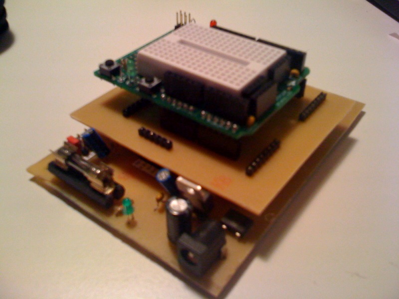
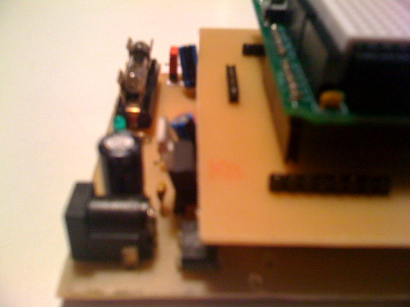
Jaluino medium is doing well ! I did print Styx PCB the wrong way, just before my holidays, so all expected tutorials have been delayed. I printed it again, and build it just yesterday. It works ok, I can plug my Arduino breadboard (see low quality photos).
I also planned to start to write documentation. Now we're going with DITA, I'm ready to write, but don't know where to start !...
Cheers,
Seb
Richard
>
> I've also noticed shields, when plugged, get in contact with 7805 and the
> cap above. I think I've respected shield's measures (85mm x 74mm), so it's
> not bigger as expected. Do you think these parts could be placed a little
> more on the left, to make room for shields ?
> Please send photos ! And maybe put schematic & PCB under SVN, as a new
> shield ? I may need this shield in tutorials (I prefer showing a "pure"
> Jaluino breadboard shield, than Styx + Arduino's)
arduino shield, should I add at least 1 led and 1 or to switches?
> How will you decide whether PWM is for LEDs or motors ? Jumpers ?
attached led is indication of effective output power
> As for motor controller chips, I've tested L293D and SN754410 (http://sirloon.net/loonaweb/sirblog/driving-dc-motors-with-a-pic-16f8...)
> decided to connect PWM signals directly to RC tank H-bridges (though it
> probably damages on-board chip, but that's ok I won't use it...).
a dc motor
> Maybe something to plug a buzzer on a PWM channel to play with sounds ?
universal PWM output with al little power :-)
>
> Jaluino medium is doing well ! I did print Styx PCB the wrong way, just
> before my holidays, so all expected tutorials have been delayed. I printed
> it again, and build it just yesterday. It works ok, I can plug my Arduino
> breadboard (see low quality photos).
> I also planned to start to write documentation. Now we're going with DITA,
> I'm ready to write, but don't know where to start !...
How do i inlude pictures in this message
(see pictures in file section)
-Greetz
Richard
Sebastien Lelong
I will see wat I can do
>
> I've also noticed shields, when plugged, get in contact with 7805 and the
> cap above. I think I've respected shield's measures (85mm x 74mm), so it's
> not bigger as expected. Do you think these parts could be placed a little
> more on the left, to make room for shields ?
OK !
This shield for now has no extra led and switches like I see on your
> Please send photos ! And maybe put schematic & PCB under SVN, as a new
> shield ? I may need this shield in tutorials (I prefer showing a "pure"
> Jaluino breadboard shield, than Styx + Arduino's)
arduino shield, should I add at least 1 led and 1 or to switches?
I don't know what worth to be included.
LED and switch aren't connected to the breadboard (actually shield & breadboard are sold separately), it's up to user to decide to connect LED/switch to breadboard.
Indeed, being able to connect a LED and/or a switch may be handy.
no selection, no dc motor attached is only led and with dc motor
> How will you decide whether PWM is for LEDs or motors ? Jumpers ?
attached led is indication of effective output power
> As for motor controller chips, I've tested L293D and SN754410 (http://sirloon.net/loonaweb/sirblog/driving-dc-motors-with-a-pic-16f8...)
> with not so much success. It was for driving an RC tank. I've finallyit is just for testing PWM with a little power (BD139) so directly on
> decided to connect PWM signals directly to RC tank H-bridges (though it
> probably damages on-board chip, but that's ok I won't use it...).
a dc motor
OK
buzzer can be connected on PWM output same as for dc motor it’s a
> Maybe something to plug a buzzer on a PWM channel to play with sounds ?
universal PWM output with al little power :-)
OK again ;)
>Yeah, I love it, very nice indeed.
> Jaluino medium is doing well ! I did print Styx PCB the wrong way, just
> before my holidays, so all expected tutorials have been delayed. I printed
> it again, and build it just yesterday. It works ok, I can plug my Arduino
> breadboard (see low quality photos).
>I know that problem, I am a horrible writer
> I also planned to start to write documentation. Now we're going with DITA,
> I'm ready to write, but don't know where to start !...
I'll start with something, we'll see where we'll go. Iterative process.
Will you (and other of course) review it ?
How do i inlude pictures in this message
Just attach files to your mail. Or maybe you're using Web interface from google group ?
Cheers,
Seb
Sebastien Lelong
How do i inlude pictures in this message
(see pictures in file section)
Did you actually cut a half of a breadboard to put on your breadboard shield ?
Seb
Richard
soldering
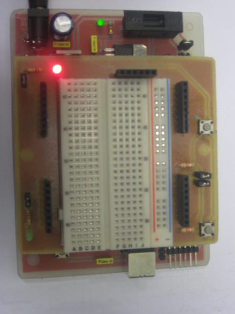
i finished now a shield with 2 leds and 2 switches and breadboard (2nd
half :-)).
i will upload some pictures.
i use Web interface from google group how can i use my outlook with
jallib?
greetz
Richard
Sebastien Lelong
Yes, cut a board in less than half and stick it on your shield, so no
On 2 okt, 13:53, Sebastien Lelong <sebastien.lel...@gmail.com> wrote:
> > How do i inlude pictures in this message
>
> > (see pictures in file section)
>
> Very, very nice ! your jaluino is very clean, much more than mine :)
> Did you actually cut a half of a breadboard to put on your breadboard shield
> ?
soldering
i finished now a shield with 2 leds and 2 switches and breadboard (2nd
half :-)).
i will upload some pictures.
And PCB/schematic ?
i use Web interface from google group how can i use my outlook with
jallib?
Every posts are sent to your email, and you can post by sending mail to jal...@googlegroups.com . So you just have to configure Outlook to point to your email (rich...@hetnet.nl).
Cheers,
Seb
Richard
>
> And PCB/schematic ?
>
maybe this evening, together with jaluino_medium_12a with more space
for shield :-).
greetz
Richard
Sebastien Lelong
This shield for now has no extra led and switches like I see on your
arduino shield, should I add at least 1 led and 1 or to switches?
Seb
Richard
On Oct 2, 7:52 pm, Sebastien Lelong <sebastien.lel...@gmail.com>
wrote:
breadboard) is already in svn
where are the 100nF caps placed on power lines? .
Greetz
Richard
>
> Seb