Re: jaluino (first schematic... Richard ?)

Sebastien Lelong
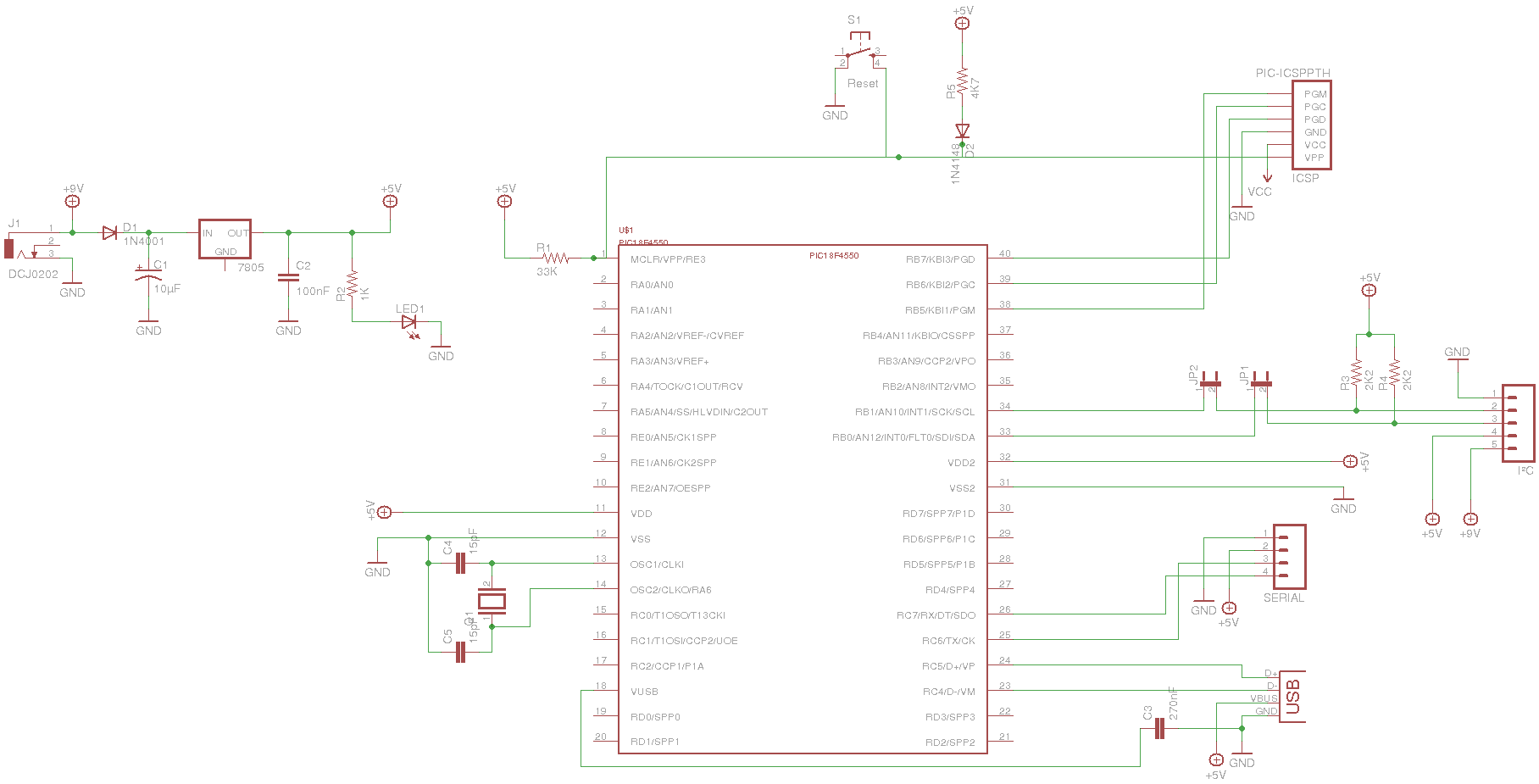
I tried to draw a schematic for this Jaluino board, 18F4550 based, but
this is not my "cup of tea"... Attached is a picture + eagle
schematic, showing the whole:
Few questions/remarks:
- For now, I put two jumpers for I²C resistors. Joep I understood
you'd put pad so users can solder it or not, whether they want i2c. I
would prefer a reversible solution..
- I took as much as I could from Albert & Richard's 18F14K5°
schematic about USB, but I'm not sure it's all correct...
- I still need to put some parts for Tiny bootloader software reset.
Has anyone already experienced this feature ?
- about ISCP: connector has a Vcc pin. Is it +5V ? Or the power
supplied by the programmer (something like 12/13V) ? I've consider Vcc
as a third power supply, with +9V (from battery of wallmart power
supply) and +5V, produced from 9V or USB.
- I still need to put connectors for all pins. My question is: do we
want to put all pins in connectors, even those already involved in
something ? Ex: pin TX is involved in serial. Should this pin be
connected to a connector, thus exported to user, or not ?
Can you guys give a look at it ? Any comments ? Ideas ?
Maybe Richard Zengerink could help us with that, as he's our
schematic/PCB guru... Richard ?
Cheers,
Seb
--
Sébastien Lelong
http://www.sirloon.net
http://sirbot.org
> 2009/7/20 Sebastien Lelong <sebastie...@gmail.com>:
>>
>>> And if we do none of the above, we can have a 4-pin header:
>>> - ground
>>> - 5v
>>> - tx
>>> - rx
>>> Cheap, small and still ease to access serial port (with only one
>>> convertor you like for all your boards).
> These are the lower 4 pins of the 8-pin connector you see on all my
> boards. The upper 8 are for ICP.
>
>>> > - I²C: alsways a must. An "I²C ready" board allows many experiments
>>> > and is opened to many 3rdparty chips.
>>> I propose a 5-pin header here with the following layout:
>>> - ground
>>> - scl
>>> - sda
>>> - 5v (= regulated ps of pic)
>>> - 9v (= unregulated input ps)
>>
>> Looks ok for me. With such a standardized connector, we'll able to easily
>> plug multiple jaluino boards together...
> Again, I have a lot of experience with this kind of layout. Especially
> the combitation of the two power supplies well surprisingly. It can be
> used for power distribution at both levels within the same system. And
> since it are different pins, mistakes result in system parts not
> having power, not releasing smoke ;)
>
>>> And optional pull-up resistors.
>>
>> You mean, with a jumper ?
>>
> At least a place to put them. Jumpers (you need 2) may be overkill
> (you can put a 2-pin header at the resistor's place and put the
> resistors on there if you to switch often). Two soldering pads could
> be usefull if the space is there.
>
> Joep
>
> >
>

funlw65
(in fact, Microchip microcontrllers) are connected to serial interface
via 3 resistors, no MAX chip between... and everything is just fine. I
used the same thing to transmit data from my chip (12F675) to PC and
also I used a 12F683/PICAXE 08M to upload the program (many times)
into de chip via serial cable with only 3 wires and 3 resistors.:
For receiving pin (no divider):
22K
________
---------------+------|________|----------------> to chip
|
|
_
| |
| | 10K
|_|
|
|
GND
For transmission to PC, a serial resistor of 180R is used. I think
this is a fast and cheap way to receive/send data from/to PC. Is also
secure. And there are many users of PICAXE prepared chips....
Vasi
On Jul 20, 10:42 pm, Sebastien Lelong <sebastien.lel...@gmail.com>
wrote:
> 79KViewDownload
>
> jaluino_sch1.png
> 43KViewDownload
Sebastien Lelong
Nice schematic, I can't wait to see the layout. I know PICAXE chips
(in fact, Microchip microcontrllers) are connected to serial interface
via 3 resistors, no MAX chip between... and everything is just fine.
I think this assumes the peripheral on the other side (eg. a PC) understands RS232 level between 0 and 5V, instead of -12V and +12V. It's sometime the case, and to be sure, using a MAX232 chip is better. That said, with the "plug your own serial module" option, you can choose whatever you want. This gives a fourth option, a the cheap side, so we new have:
- FTDI chip based USB-to-serial adaptor
- 18F14K50 based USB-to-serial adaptor
- MAX232 based, with DB9 connector
- resistor based, with DB9 connector
- (and last option: "my own way to deal with serial")
Some more thoughts about the board. Original Arduino Diecimila uses a Atmega168, a 28-pins chip.
See: http://arduino.cc/en/Main/ArduinoBoardDiecimila . From this, 20 pins are "exported" through connectors on sides, where 2 pin are dedicated to RX/TX, thus involved in board's functionality (I mean there aren't completely free, as they are involved in serial).
Using a 18F4550, there are a lot more pins: 40. From these 40 pins, only 33 can be used: 2 x 2 pins for Vss/Vdd, 1 pin for MCLR, and 2 pin for OSC/Xtal. The board will provide serial (2 pins), USB (3 pins), optionally I²C (2 pin). Even if these pins are already involved in something on the board (a functionality), I think they all should be exported. This will finally give 33 pins which can be exported, plug to side connectors. This is 15 pins more than official Arduino.
My question is: how will we be pin-compatible with existing Arduino shields ? My answer would be: Jaluino board won't be compatible, but we can design a shield to it adapts Jaluino to Arduino connectors.
Any suggestions, advices, comments, ... ?
Also note some Arduino-like big fat boards, with far more than 28-pin chip exist:
http://arduino.cc/en/Main/ArduinoBoardMega
http://www.liquidware.com/shop/show/ILL/Illuminato
Sebastien Lelong
Nice schematic, I can't wait to see the layout. I know PICAXE chips
(in fact, Microchip microcontrllers) are connected to serial interface
via 3 resistors, no MAX chip between... and everything is just fine.
- FTDI chip based USB-to-serial adaptor
- 18F14K50 based USB-to-serial adaptor
- MAX232 based, with DB9 connector
- resistor based, with DB9 connector
- (and last option: "my own way to deal with serial")
Some more thoughts about the board. Original Arduino Diecimila uses a Atmega168, a 28-pins chip.
See: http://arduino.cc/en/Main/ArduinoBoardDiecimila . From this, 20 pins are "exported" through connectors on sides, where 2 pin are dedicated to RX/TX, thus involved in board's functionality (I mean there aren't completely free, as they are involved in serial).
Using a 18F4550, there are a lot more pins: 40. From these 40 pins, only 33 can be used: 2 x 2 pins for Vss/Vdd, 1 pin for MCLR, and 2 pin for OSC/Xtal. The board will provide serial (2 pins), USB (3 pins), optionally I²C (2 pin). Even if these pins are already involved in something on the board (a functionality), I think they all should be exported. This will finally give 33 pins which can be exported, plug to side connectors. This is 15 pins more than official Arduino.
My question is: how will we be pin-compatible with existing Arduino shields ? My answer would be: Jaluino board won't be compatible, but we can design a shield to it adapts Jaluino to Arduino connectors.
Any suggestions, advices, comments, ... ?
Also note some Arduino-like big fat boards, with far more than 28-pin chip exist:
http://arduino.cc/en/Main/ArduinoBoardMega
http://www.liquidware.com/shop/show/ILL/Illuminato
funlw65
On Jul 21, 7:49 pm, Sebastien Lelong <sebastien.lel...@gmail.com>
wrote:
> RS232 level between 0 and 5V, instead of -12V and +12V. It's sometime the
> case, and to be sure, using a MAX232 chip is better. That said, with the
> "plug your own serial module" option, you can choose whatever you want. This
> gives a fourth option, a the cheap side, so we new have:
>
> - FTDI chip based USB-to-serial adaptor
> - 18F14K50 based USB-to-serial adaptor
> - MAX232 based, with DB9 connector
> - resistor based, with DB9 connector
> - (and last option: "my own way to deal with serial")
can be a fast solution to test the software but yes, is not a good
ideea.
> Some more thoughts about the board. Original Arduino Diecimila uses a
> Atmega168, a 28-pins chip.
> RX/TX, thus involved in board's functionality (I mean there aren't
> completely free, as they are involved in serial).
ATmega168 pins, to see some similarities at ports level but I think
the key is at software level. And is the only level where Pinguino
offers Arduino compatibility (and maybe the reason why the author
didn't offered a shielded variant).
For "reusing" Arduino shields, I think a study must be done. Studying
different shields with their software to see how interact with the
board. In what manner are used digital pins, etc. ... Because I don't
think they take in account very much the particularities of the chip
himself (I think the software is hiding the hardware).
Maybe is too much work but a shielded board is a must, even if not
Arduino compatible. This is jallib team decision, and I hope a good
board will increase the number of programmers using jal language
(unfortunately, the fact that jal don't have a math library is another
obstacle regarding to "mass" adoption - the new comers remain with
basic languages and advanced people go to C language).
Sebastien Lelong
spend days to get a decent PCB...
Seb
2009/7/21 funlw65 <fun...@gmail.com>:

Richard Gentle-Green

Joep Suijs
> (unfortunately, the fact that jal don't have a math library is another
> obstacle regarding to "mass" adoption - the new comers remain with
> basic languages and advanced people go to C language).
I recall someone (you?) mentioned math functions once before. Is this
realy an issue? And which math functions would be required?
Although it might not be cheap (both in development and use), it
should be do-able.
Joep
funlw65
I'm a newbie in microcontrollers but I can give you examples. When you
make controllers (windmill/solar, or weather stations, etc.), in
locations far away from buildings, you can't let your PC there for
data interpretation and displaying graphs and results... You will need
the controller to do calculations and displaying them on a LCD
display... In general, for newbies as I am, is easy to use math
functions, even if is not efficient ... Is enough if chip is doing his
job.
Anyway, it will be a complete compiler/language. And why not? Every
language on the market have math functions.
Vasi
Joep Suijs
Personaly, I needed sin() and created some code for this, based on
fixed point math. But I think float math and log functions are of an
other magnitude.
2009/7/21 funlw65 <fun...@gmail.com>:
> In general, for newbies as I am, is easy to use math
> functions, even if is not efficient ... Is enough if chip is doing his
> job.
Untill it takes up such a part of your program memory that the rest of
your program does not fit any more...
> Anyway, it will be a complete compiler/language. And why not? Every
> language on the market have math functions.
It could be done. But it will require a major investment in
development time and it must be clear this time is better spent on
this then on other a bunch of whishes...
Joep
funlw65
here is a floating point library 24/32 bit made by Ziya Erdemir (year
2003 ?!?) but it require an external converter (you must admit that
newbies will go to something easier - not a problem for me to use it).
Better this to be supported by compiler. Or maybe something as in
PicBasic Pro, on their site is a FP.zip floating point library and
examples how to use it (without external converters) ... or maybe I
didn't understood, as usual :P .
On Jul 22, 12:00 am, Joep Suijs <jsu...@gmail.com> wrote:
> You still leave the question unanswerd which mathfunctions would be required.
> Personaly, I needed sin() and created some code for this, based on
> fixed point math. But I think float math and log functions are of an
> other magnitude.
>
Sebastien Lelong
The connector's layout is very important, as all shields will have to be compatible, and will reproduce this layout.
For instance, Arduino diecimila has 4 connectors:
- 2 on on this upper side
- 2 on the bottom side, 1 being reserved to power
Arduino mega uses a much bigger AVR than Diecimila. They put a double row connector, on the right side. Still, the four previous connectors are on the same place. As a consequence, shield for Diecimila can be used with Mega.
I'd like to reproduce the same. If we build first Jaluino board, 18F2550, it could have the same connectors as in Arduino (2 on upper side, 2 on bottom side). Next step is a 18F4550 based board. We could add a single row connector on the right. In the future, if we decide an even bigger PIC, we'll be able to double this left connector.
That said, I still can't produce a PCB, I'm having a lot of trouble placing parts to avoid vias... Any PCB guru here ?
PS: as a bonus (...) here's my last schematic, with connectors.
Cheers,
Seb
funlw65
anymore... so I think you can't get rid of vias and bridges on 4550.
On Jul 22, 10:37 pm, Sebastien Lelong <sebastien.lel...@gmail.com>
wrote:
> modify the subject plz ?)...
>
> The connector's layout is very important, as all shields will have to be
> compatible, and will reproduce this layout.
> For instance, Arduino diecimila has 4 connectors:
>
> - 2 on on this upper side
> - 2 on the bottom side, 1 being reserved to power
>
> Arduino mega uses a much bigger AVR than Diecimila. They put a double row
> connector, on the right side. Still, the four previous connectors are on the
> same place. As a consequence, shield for Diecimila can be used with Mega.
>
> I'd like to reproduce the same. If we build first Jaluino board, 18F2550, it
> could have the same connectors as in Arduino (2 on upper side, 2 on bottom
> side). Next step is a 18F4550 based board. We could add a single row
> connector on the right. In the future, if we decide an even bigger PIC,
> we'll be able to double this left connector.
>
> That said, I still can't produce a PCB, I'm having a lot of trouble placing
> parts to avoid vias... Any PCB guru here ?
>
> PS: as a bonus (...) here's my last schematic, with connectors.
>
> Cheers,
> Seb
>
>
>
> > First try to get a PCB layout gives way too much vias. This is where I
> > spend days to get a decent PCB...
>
> > Seb
>
> 56KViewDownload
funlw65
Sebastien Lelong
Seb
funlw65
help :P and someone made something about : single sided and using
4550 ). But forget about if that don't help you.
On Jul 23, 8:09 pm, Sebastien Lelong <sebastien.lel...@gmail.com>
wrote:
>
> Seb
>
funlw65
many vias? Other experts then can optimize the board (if is
possible).
Sebastien Lelong
I think this is because of dedicated connectors (serial, i2c, etc...) which make the thing more complex.
I'm about to finish my post on jalliblog about Jaluino. Kind of specs... Guys, I'm waiting for your feedback, suggestions, comments, etc... !
Cheers,
Seb
Nope. Look at it as an another example of PCBing a 4550 (you asked for
help :P and someone made something about : single sided and using
4550 ). But forget about if that don't help you.
On Jul 23, 8:09 pm, Sebastien Lelong <sebastien.lel...@gmail.com>
wrote:
> Nice ! Should we use this instead of building Jaluino ?
>
> Seb
>
Joep Suijs
connectors of dwarf boards (and turning them around still has + and -
swapped)...
2009/7/23 funlw65 <fun...@gmail.com>:

a.f...@chello.nl
Some comments on the schematic:
In the current schematic the 5V and USB-5V are connected, this is not
according to spec,
see also the datasheet about USB self-powering. Either way, use a
jumper selection for the
power supply or use some shottky diodes, in addition it might be wise
to place a by-pass diode
across the 7805, since these devices don't like to be reversed
powered.
Why R1? I think you can remove it, since the reset pin is held high
via R5/D2
Be sure to put a 100n bypass close to VSS/VDD pins of the PIC, I don't
know if C2 is the PIC bypass cap, if so I would
draw it closely to the PIC VSS/VDD pins
BTW, the 18f14k50 board is working fine
Albert
On Jul 22, 9:37 pm, Sebastien Lelong <sebastien.lel...@gmail.com>
wrote:
> modify the subject plz ?)...
>
> The connector's layout is very important, as all shields will have to be
> compatible, and will reproduce this layout.
> For instance, Arduino diecimila has 4 connectors:
>
> - 2 on on this upper side
> - 2 on the bottom side, 1 being reserved to power
>
> Arduino mega uses a much bigger AVR than Diecimila. They put a double row
> connector, on the right side. Still, the four previous connectors are on the
> same place. As a consequence, shield for Diecimila can be used with Mega.
>
> I'd like to reproduce the same. If we build first Jaluino board, 18F2550, it
> could have the same connectors as in Arduino (2 on upper side, 2 on bottom
> side). Next step is a 18F4550 based board. We could add a single row
> connector on the right. In the future, if we decide an even bigger PIC,
> we'll be able to double this left connector.
>
> That said, I still can't produce a PCB, I'm having a lot of trouble placing
> parts to avoid vias... Any PCB guru here ?
>
> PS: as a bonus (...) here's my last schematic, with connectors.
>
> Cheers,
> Seb
>
>
>
>
>
> > First try to get a PCB layout gives way too much vias. This is where I
> > spend days to get a decent PCB...
>
> > Seb
>
> 56KViewDownload- Hide quoted text -
>
> - Show quoted text -
Sebastien Lelong
OK, this is where I'm lost...:)
In the current schematic the 5V and USB-5V are connected, this is not
according to spec,
see also the datasheet about USB self-powering.
OK, I'll try to have a look...
Either way, use a
jumper selection for the
power supply or use some shottky diodes,
? :)
Any schematic I could refer to ?
in addition it might be wise
to place a by-pass diode
across the 7805, since these devices don't like to be reversed
powered.
Isn't it D1 for ?
Why R1? I think
you can remove it, since the reset pin is held high
via R5/D2
Yes, you're right. Do you think R5 should have a higher value then ?
Be sure to put a 100n bypass close to VSS/VDD pins of the PIC, I don't
know if C2 is the PIC bypass cap, if so I would
draw it closely to the PIC VSS/VDD pins
OK !
BTW, the 18f14k50 board is working fine
Great, maybe part of it could be used to create Jaluino Mini...
Seb
Sebastien Lelong
I tried to do some research, but I'm lost, this is far beyond my understanding and I can't figure out how to deal with self-power USB... I need your help, would you mind giving me an example of self-powered USB vs. not self-power USB ? Your 18F14K50 PIC is self-power isn't ? I can't see the difference with my schematic...
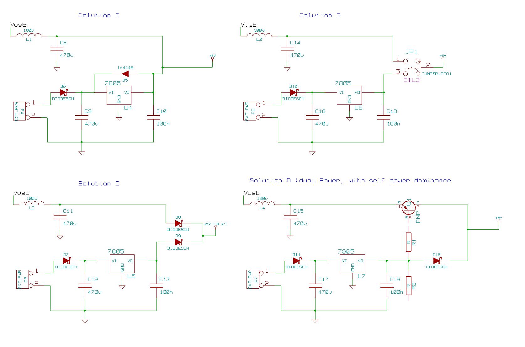
Also, I've found something about using a shottky diode to select +5V from regulator or +5V from USB (see picture, part of schematic from an Arduino board). Is that what you were talking about ?
Cheers,
Seb
a.faber
Attached 4 possible solutions
Solution A: Almost the current solution, except added a bypass diode across
the 7805, so it won't blow up if there is USB 5V and not external 9v
Solution B: Current solution, except make power selection via a jumper
selection (less user friendly, no voltage drop)
Solution C: Auto power selection via 2 schottky diodes (drawback, voltage
drop of ~0.3v)
Soltionn D: Auto power selection with self power dominance (drawback,
voltage drop of ~0.3v)
General remarks:
D6, D7, D10, D11 in my schematic does not have to be a schottky type if the
external supply is > ~8V
L1,L2,L3,L4 (ferrite bead, or power choke), not realy required, but
recommended
Albert
----- Original Message -----
From: "Sebastien Lelong" <sebastie...@gmail.com>
To: <jal...@googlegroups.com>
Sent: Saturday, July 25, 2009 12:42 PM
Subject: [jallib] Re: jaluino (first schematic... Richard ?)
> > Sbastien Lelonghttp://www.sirloon.nethttp://sirbot.org
> > jaluino_sch2.png
> > 56KViewDownload- Hide quoted text -
> >
> > - Show quoted text -
> >
>
--
http://www.sirloon.net
http://sirbot.org
Sebastien Lelong
And many thanks for this ! For now, I think I'll go with solution B, which is the one I understand the most...
Seb
--
Sébastien Lelong
http://www.sirloon.net
http://sirbot.org
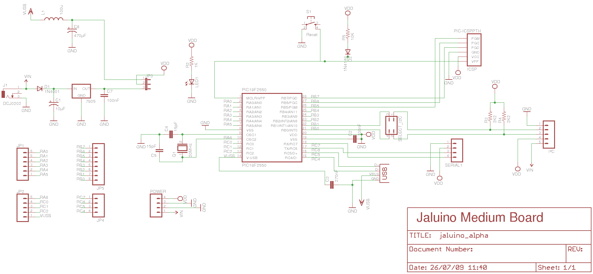
Sebastien Lelong
Here's a new schematic for Jaluino Medium board:18F4550 is replaced by smaller 18F2550, so the PCB layout is expected to be easier, helping focus on schematic rather than layout issues. I've recently received a couple of them, so I'll be able to prototype few things.
I tried to include Albert's suggestions, hoping it's correct now... Power supply can be from USB or external, selected using a jumper.
Any comments ?
Cheers,
Seb

Richard
Just got back from holyday and trying to get through the jallib and
jallist mails :-).
I noticed this topic and if you want I can help you with creating a
nice main board.
Maybe it’s an idea to make a nice double sided main board with a
18f4550 with all furthers
And extension possibility’s instead of a small single sided one which
will have its limitations
Of course people must buy this board but shall cost not more than
approx. €15 to €20
all extension board we can try to design as single side so home made
versions.
At this moment I don’t have match time but maybe we can discus this
and other options a bit more.
Greetz
Richard
On Jul 26, 11:43 am, Sebastien Lelong <sebastien.lel...@gmail.com>
wrote:
>
> Here's a new schematic for Jaluino Medium board:18F4550 is replaced by
> smaller 18F2550, so the PCB layout is expected to be easier, helping focus
> on schematic rather than layout issues. I've recently received a couple of
> them, so I'll be able to prototype few things.
>
> I tried to include Albert's suggestions, hoping it's correct now... Power
> supply can be from USB or external, selected using a jumper.
>
> Any comments ?
>
> Cheers,
> Seb
>
>
>
>
>
> > Hi Albert,
>
> > And many thanks for this ! For now, I think I'll go with solution B, which
> > is the one I understand the most...
>
> > Seb
>
> 51KViewDownload- Hide quoted text -
Sebastien Lelong
Hope your holidays were nice ! (they usually are...)
I noticed this topic and if you want I can help you with creating a
nice main board.
Great, good to hear !
Maybe it’s an idea to make a nice double sided main board with a
18f4550 with all furthers
And extension possibility’s instead of a small single sided one which
will have its limitations
Of course people must buy this board but shall cost not more than
approx. €15 to €20
all extension board we can try to design as single side so home made
versions.
Having a double sided main board would be great, but it may be too early for now. I think we should first experiment what's a good board is, the place of shield connectors, and mostly how people would want to actually buy a professional looking board.
Because 18F4550 gives a too complex PCB layout for a single sised board, I've focused on a smaller version using 18F2550. I've posted few things on jalliblog, included my last schematic & PCB: http://jallib.blogspot.com/search/label/jaluino
Do you any weird things ? I've not tested it yet, but it's Work In Progress...
Seb
funlw65
http://sites.google.com/site/funlw65/electronics/jaluino-pinguino-28-pins-starting-bo/freejalduino
On Jul 26, 12:43 pm, Sebastien Lelong <sebastien.lel...@gmail.com>
wrote:
>
> Here's a new schematic for Jaluino Medium board:18F4550 is replaced by
> smaller 18F2550, so the PCB layout is expected to be easier, helping focus
> on schematic rather than layout issues. I've recently received a couple of
> them, so I'll be able to prototype few things.
>
> I tried to include Albert's suggestions, hoping it's correct now... Power
> supply can be from USB or external, selected using a jumper.
>
> Any comments ?
>
> Cheers,
> Seb
>
>
>
> > Hi Albert,
>
> > And many thanks for this ! For now, I think I'll go with solution B, which
> > is the one I understand the most...
>
> > Seb
>
> 51KViewDownload
Sebastien Lelong
(btw have you also check my last try ? http://jallib.blogspot.com/2009/08/jaluino-medium-18f2550-based-first.html)
Cheers,
Seb
Joep Suijs
Mabe a bit late, but why don't you take 40pin chip?
I once used an arduino but ran out of pins before the end of my
project. And earlier this week, a friend brought a arduinomega -
atmege1280 processor with plenty of flash, ram and pins. Great! (too
bad he took it back with him...)
Joep
2009/8/6 Sebastien Lelong <sebastie...@gmail.com>:
Sebastien Lelong
- mini: 18F14K50 (20 pins)
- medium: 18F2550 (28 pins)
- maxi: 18F4550 (40 pins)
(- awesome: 18F87J50 (80 pins))
I was first thinking about building a 18F4550-based board, but the PCB layout is complicated, and I wanted to focus on shematic issues instead of resolving PCB issues. 18F2550 gives a simpler PCB, should be easy to build at home.
As Richard suggested, maybe a double-sisded 18F4550-based board would be a nice idea. People would have to pay for it, because it can't be produced "by hand". It think it's a little bit too early to go this way, there may not be enough users at all. (though being able to buy a kit could get more users than letting them building it on their own).
funlw65
I think is ok (all PWM requirements for an Arduino shield can be meet)
Yes, we have more than 6 analog pins if we want. No problem, you can
use all 10 if your application require that (with JAL or another
language).
Yes, you don't have compatibility at port level. But they use generic
numbers for their pins... as Pinguino is doing. Pinguino can benefit
from Arduino applications only at software level, the hardware must be
re-designed.
About schematic, I said I lost the consistency between board and
schematic.. I intend to post it, of course but here is only the reset
circuit.
And another goal was to use the Fritzing software for shield
development.
On Aug 6, 5:44 pm, Sebastien Lelong <sebastien.lel...@gmail.com>
wrote:
> compatible with Arduino ? That is, connectors carrying the same pins, with
> the exact same position ? I'm not sure it makes sense, because as for PWM,
> there aren't 6 PWM channels in a 18F2550. I guess Pinguino offers more
> channels but it's in software, not in hardware. Same for ADC: Arduino has 6
> of them, 18F2550 has 10. How will you deal with that ?
>
>
> Cheers,
> Seb
> 2009/8/6 funlw65 <funl...@gmail.com>
>
>
> > My trial on Arduino layout
>
>
> read more »
funlw65
panel and weather station controllers).
I intend to use a 4550 for a USB CNC Router (even if I don't know how
to do it yet) but I don't see it as a general board, is too complex to
be made at home (not a pretty one).
On Aug 6, 5:55 pm, Joep Suijs <jsu...@gmail.com> wrote:
> Hi,
>
> Mabe a bit late, but why don't you take 40pin chip?
> I once used an arduino but ran out of pins before the end of my
> project. And earlier this week, a friend brought a arduinomega -
> atmege1280 processor with plenty of flash, ram and pins. Great! (too
> bad he took it back with him...)
>
> Joep
>
> > Interesting but there's no schematic... Also, do you really want to make it
> > compatible with Arduino ? That is, connectors carrying the same pins, with
> > the exact same position ? I'm not sure it makes sense, because as for PWM,
> > there aren't 6 PWM channels in a 18F2550. I guess Pinguino offers more
> > channels but it's in software, not in hardware. Same for ADC: Arduino has 6
> > of them, 18F2550 has 10. How will you deal with that ?
>
> > (btw have you also check my last try ?
> > 2009/8/6 funlw65 <funl...@gmail.com>
> >> My trial on Arduino layout
>
>
> read more »
Richard
Hello,
I have made a schematic with a 18f2550 (jaluino medium) as something
to discussion about.
IMHO we should develop an own standard for Jaluino, off course using
the good ideas from other boards but not making exactly the same.
Jaluino is for Jal and developed by Jal (people).
I suggest to make the Jaluino mini pin compatible with a breadboard,
easy for testing.
If you all agree I can make all the schematics and pcb layouts.
I have placed the 18f2550 in the file section so we can discus it
before making the layout.
After that I can make the other schematics so we can disbud them
before making those layouts.
As you can see I also added a pushbutton and led so without a shield
you can already work with usb, serial,i2c and do the, “blink a led”
tests and have a input.
I was thinking of making the pcb size of Jaliuno medium and maxi ½ a
eurocard (100x160) would be 100x80 but that is for later.
Ps. Joep I am not forgetting the format library, have some idea that I
will discus with you all later.
Greetz
Richard
Joep Suijs
>
> Ps. Joep I am not forgetting the format library, have some idea that I
> will discus with you all later.
>
jallib last couple of months. Build a forth compiler for my robot and
have to finish a few more things before the next 'builders day' in
september (dutch link:
http://wiki.robotmc.org/index.php?title=Team_Building_Day)
But you are right, it's something which is still on our list and we
will handle it in due time.
Joep
AlbertF
> jallib last couple of months. Build a forth compiler for my robot and
> have to finish a few more things before the next 'builders day' in
> september (dutch link:http://wiki.robotmc.org/index.php?title=Team_Building_Day)
however I have not finished
yet my bot and will go on holiday in the beginning of September (bad
timing), hopefully
can join next year..
Albert

mattschinkel
My hard disk lib uses 23 pins + whatever else I want to hook up.
On Aug 6, 7:55 am, Joep Suijs <jsu...@gmail.com> wrote:
> Hi,
>
> Mabe a bit late, but why don't you take 40pin chip?
> I once used an arduino but ran out of pins before the end of my
> project. And earlier this week, a friend brought a arduinomega -
> atmege1280 processor with plenty of flash, ram and pins. Great! (too
> bad he took it back with him...)
>
> Joep
>
>
>
> > Interesting but there's no schematic... Also, do you really want to make it
> > compatible with Arduino ? That is, connectors carrying the same pins, with
> > the exact same position ? I'm not sure it makes sense, because as for PWM,
> > there aren't 6 PWM channels in a 18F2550. I guess Pinguino offers more
> > channels but it's in software, not in hardware. Same for ADC: Arduino has 6
> > of them, 18F2550 has 10. How will you deal with that ?
>
> > (btw have you also check my last try ?
> > 2009/8/6 funlw65 <funl...@gmail.com>
> >> My trial on Arduino layout
>
>
> read more »- Hide quoted text -
Sebastien Lelong
Very nice, thanks for your help !
IMHO we should develop an own standard for Jaluino, off course using
the good ideas from other boards but not making exactly the same.
Jaluino is for Jal and developed by Jal (people).
I agree 100%
I suggest to make the Jaluino mini pin compatible with a breadboard,
easy for testing.
Yes, pluggable on a breadboard.
If you all agree I can make all the schematics and pcb layouts.
I have placed the 18f2550 in the file section so we can discus it
before making the layout.
Looks great. I can try to prototype few part of the schematic if you want.
After that I can make the other schematics so we can disbud them
before making those layouts.
I have some thoughts:
- it seems you have made one connector per port (eg. one for PORTA, one for PORTB). I tried to do this as first, then realized the PCB was way too complicated because pins aren't distributed "logically", in a continued fashion (hope you know what I mean). Do you think the PCB will be simple enough to be built by ourselves ?
- I think RC4 and RC5 should be part of connector, if no USB is used, we can still use the use pin (this is what I called "exported pins": pins being part of a connector and available to shields.
- I've never tested this but if we use Tinybootloader (I'd like to), it's able to reset the PIC by setting RTS. Some hardware is required, see schematics in http://www.etc.ugal.ro/cchiculita/software/tinybldusage.htm section "Options". Having the possibility to remotely reset the device is a must IMHO. I'd need to prototype and test this on a breadboard (but I'm having troubles making tiny working). I've also seen you've put a reset pin on Power connector. What would be the usage ?
hardware for reset tiny (instead of reset via power connector ?)
- partially related to previous bullet: all the serial module I have have RTC and CTS pins (bluetooth-serial converter and USB-serial FTDI based converter). Should we add this pins to serial connector ?
- finally, my USB-to-serial module also is able to provide power. This would give a third option to power supply:
1. power is taken from a wallmart power supply (jack)
2. power is taken from USB connector (the one we have in our schematics)
3. power is taken from serial module, when available (for instance, available when using USB-to-serial connector)
Is it possible to add this 3rd option ?
(last thought: Using PIC LF versions, we can make them run at lower voltages than 5V. My USB-to-serial converter also is able to provide 5V or 3.3V (and many of these provide the kind of things). Will this work with 3.3V for instance ?
As you can see I also added a pushbutton and led so without a shield
you can already work with usb, serial,i2c and do the, “blink a led”
tests and have a input.
Yes, as in original Arduino, good idea to check the board.
I was thinking of making the pcb size of Jaliuno medium and maxi ½ a
eurocard (100x160) would be 100x80 but that is for later.
The smaller the better :)
In my first attempt to make a PCB, I've reserved a space so the chosen serial module can be plugged (see bottom left part).
Richard
> Looks great. I can try to prototype few part of the schematic if you want.
> - it seems you have made one connector per port (eg. one for PORTA, one for
> PORTB). I tried to do this as first, then realized the PCB was way too
> complicated because pins aren't distributed "logically", in a continued
> fashion (hope you know what I mean). Do you think the PCB will be simple
> enough to be built by ourselves ?
schematic (without changing the working) for an improved routing.
> - I think RC4 and RC5 should be part of connector, if no USB is used, we
> can still use the use pin (this is what I called "exported pins": pins being
> part of a connector and available to shields.
lose ends to a connector.
>
> - I've never tested this but if we use Tinybootloader (I'd like to), it's
> able to reset the PIC by setting RTS. Some hardware is required, see
> must IMHO. I'd need to prototype and test this on a breadboard (but I'm
> having troubles making tiny working). I've also seen you've put a reset pin
> on Power connector. What would be the usage ?
USB bootloader (if working)
or use ICSP.
If you want to use RS232 you need to make a shield and there you can
use the RESET line (in the
power connector ) for reseting the system with in your case RST :-).
> hardware for reset tiny (instead of reset via power connector ?)
> - partially related to previous bullet: all the serial module I have have
> RTC and CTS pins (bluetooth-serial converter and USB-serial FTDI based
> converter). Should we add this pins to serial connector ?
> - finally, my USB-to-serial module also is able to provide power. This
> would give a third option to power supply:
>
> 1. power is taken from a wallmart power supply (jack)
> 2. power is taken from USB connector (the one we have in our schematics)
> 3. power is taken from serial module, when available (for instance,
> available when using USB-to-serial connector)
>
> Is it possible to add this 3rd option ?
trouble if you use standard RS232
>
> (last thought: Using PIC LF versions, we can make them run at lower voltages
> than 5V. My USB-to-serial converter also is able to provide 5V or 3.3V (and
> many of these provide the kind of things). Will this work with 3.3V for
> instance ?
3.3V
or you also need to add 5V and than every body needs to be careful not
to blow up the anything because of mixed up power.
>
> > As you can see I also added a pushbutton and led so without a shield
> > you can already work with usb, serial,i2c and do the, “blink a led”
> > tests and have a input.
>
> Yes, as in original Arduino, good idea to check the board.
reset so for there users there is no input option, but it does have a
led your right.
I was also thinking about placing a potentiometer for analog options
but did not because of probably layout problems (see Alberts blog on
18f14K50 where we did use a potentiometer).
But off course as I set before “use the good things from other
Boards” :-) so were I can I will.
>
>
>
> > I was thinking of making the pcb size of Jaliuno medium and maxi ½ a
> > eurocard (100x160) would be 100x80 but that is for later.
>
> The smaller the better :)
> In my first attempt to make a PCB, I've reserved a space so the chosen
> serial module can be plugged (see bottom left part).
greetz
Richard
Sebastien Lelong
> Looks great. I can try to prototype few part of the schematic if you want.
please do, thanks
I'll do my best but it'll take time.
I know but when using USB, lines must be as short as possible so no
> - I think RC4 and RC5 should be part of connector, if no USB is used, we
> can still use the use pin (this is what I called "exported pins": pins being
> part of a connector and available to shields.
lose ends to a connector.
But if not using USB, you'll loose two precious pins... Is it possible to connect RC4/RC5 to USB connector (as short as possible) and yet having them going to the connector ?
>> schematics inhttp://www.etc.ugal.ro/cchiculita/software/tinybldusage.htm section
> - I've never tested this but if we use Tinybootloader (I'd like to), it's
> able to reset the PIC by setting RTS. Some hardware is required, see
> "Options". Having the possibility to remotely reset the device is aAlbert made a bootloader for USB in this schematic the idea is using
> must IMHO. I'd need to prototype and test this on a breadboard (but I'm
> having troubles making tiny working). I've also seen you've put a reset pin
> on Power connector. What would be the usage ?
USB bootloader (if working)
or use ICSP.
Mmhh... USB bootloader is far bigger than Tinybootloader. Saves space. Except for Jaluino Mini (18F14K50, breadboard pluggable, minimum hardware parts), better use Tiny.
If you want to use RS232 you need to make a shield and there you can
use the RESET line (in the
power connector ) for reseting the system with in your case RST :-).
Not necessarily if using hardware for Tiny apparently. Resetting PIC without manual operation should be available without any shields required IMO (basic and very useful feature).
see above
> hardware for reset tiny (instead of reset via power connector ?)
> - partially related to previous bullet: all the serial module I have have
> RTC and CTS pins (bluetooth-serial converter and USB-serial FTDI based
> converter). Should we add this pins to serial connector ?
But should we add a RTS and CTS to serial connectors in anyway ? So available to shields ?
No, serial delivers only a few mA of power this can give you lots of
> - finally, my USB-to-serial module also is able to provide power. This
> would give a third option to power supply:
>
> 1. power is taken from a wallmart power supply (jack)
> 2. power is taken from USB connector (the one we have in our schematics)
> 3. power is taken from serial module, when available (for instance,
> available when using USB-to-serial connector)
>
> Is it possible to add this 3rd option ?
trouble if you use standard RS232
Sure, but I'm not talking about taking power from a standard RS232, but from a USB-to-serial converter. Actually power is taken from USB.
(see this module: http://cgi.ebay.fr/FTDI-Convertisseur-USB-a-UART-TTL-pour-ATMEL-AVR-PIC_W0QQitemZ310158443602QQcmdZViewItemQQptZFR_YO_MaisonJardin_Bricolage_ElectroniqueComposants?hash=item4836e24452&_trksid=p3286.c0.m14)
Don’t see why not, but then all of your shields must be working with
>
> (last thought: Using PIC LF versions, we can make them run at lower voltages
> than 5V. My USB-to-serial converter also is able to provide 5V or 3.3V (and
> many of these provide the kind of things). Will this work with 3.3V for
> instance ?
3.3V
or you also need to add 5V and than every body needs to be careful not
to blow up the anything because of mixed up power.
OK
The schematic i have from Arduino (duemilanove) only has one PB for
>
> > As you can see I also added a pushbutton and led so without a shield
> > you can already work with usb, serial,i2c and do the, “blink a led”
> > tests and have a input.
>
> Yes, as in original Arduino, good idea to check the board.
reset so for there users there is no input option, but it does have a
led your right.
I was also thinking about placing a potentiometer for analog options
but did not because of probably layout problems (see Alberts blog on
18f14K50 where we did use a potentiometer).
But off course as I set before “use the good things from other
Boards” :-) so were I can I will.
Sure, but the goal isn't to build a development board, but a board that could be used in many projects. The idea is to expose as many pins as possible, without adding any "features" or parts (except maybe a LED. I now have doubts about a push button to test input...). Just like Arduino. On the other side, we could have a development *shield*, with all the stuff to play with, like pots, push buttons, more LEDs, etc... Just plug it on the board, and play with it (would also be a nice educational shield to create tutorials). Let's keep the main board as flexible, as versatile as possible.
chosen serial module ??? where can i see that module to have an idea
> In my first attempt to make a PCB, I've reserved a space so the chosen
> serial module can be plugged (see bottom left part).
I do have these ones (but the idea is everyone could his own. Joep uses other kind of serial modules IIRC):
* http://cgi.ebay.fr/FTDI-Convertisseur-USB-a-UART-TTL-pour-ATMEL-AVR-PIC_W0QQitemZ310158443602QQcmdZViewItemQQptZFR_YO_MaisonJardin_Bricolage_ElectroniqueComposants?hash=item4836e24452&_trksid=p3286.c0.m14
(There are many FTDI-based USB-to-serial converters out there, they work all the same... and power could be taken from this kind of module, making the board very easy to use)
* http://www.sparkfun.com/commerce/product_info.php?products_id=582
Albert also suggested to build a serial module based on a 18F14K50, just to make a conversion between USB and serial. This option would be cheaper than a FTDI-based solution.
Finally, a real DB9 serial module with MAX232 could also be used.
Seb
a.faber
>Except for Jaluino Mini (18F14K50, breadboard pluggable, minimum hardware
parts), better use Tiny.
I agree that Tiny is nice, but basically you'll have to offer the UART for
Host PC communication (same i true if you have a FTDI converter chip), if
you use native USB, you still have a UART available for JALuino shields.
>Not necessarily if using hardware for Tiny apparently. Resetting PIC
>without
>manual operation should be available without any shields required IMO
>(basic
>and very useful feature).
It is possilbe if you add a MAX-232 on the board, and connect one of the
hanshake lines via a capacitor with the reset line
>Sure, but I'm not talking about taking power from a standard RS232, but
>from
>a USB-to-serial converter. Actually power is taken from USB.
Yes this is possible, you can take the 5V from the USB connector, don't know
if you can configure the USB device current (100mAor 500mA), if you use
native USB, we can control it from the firmware and be able to draw 500 mA
max
>
> >
> > (last thought: Using PIC LF versions, we can make them run at lower
> voltages
> > than 5V. My USB-to-serial converter also is able to provide 5V or 3.3V
> (and
> > many of these provide the kind of things). Will this work with 3.3V for
> > instance ?
>
> Dont see why not, but then all of your shields must be working with
> 3.3V
> or you also need to add 5V and than every body needs to be careful not
> to blow up the anything because of mixed up power.
You dont need a LF device, the standard F devices will run at 3.3 volt as
well
>Albert also suggested to build a serial module based on a 18F14K50, just to
>make a conversion between USB and serial. This option would be cheaper than
>a FTDI-based solution.
And is available in DIP housing, so far more homebrew friendly than TSOP or
QFN devices,
You can buy pre-fabbed FTDI modules, but they are in the 10-30 Euro range,
but the problem with
these pre-fabbed units is that we dont know when they become obsolete, so
there is a great risk
that these units can not be bought next year..
I know that the 18f14k50 is not easily to obtain (except from Farnell,
Digikey & Microchip direct), but we might do setup a group buy for 18f14k50
devices, besides the PIC only a capacitor, 12 MHz crystal
and USB connector is required, so < 5 Euro on parts, to make a USB->RS-232
converter.
Albert
Joep Suijs
> I know that the 18f14k50 is not easily to obtain (except from Farnell,
> Digikey & Microchip direct), but we might do setup a group buy for 18f14k50
> devices, besides the PIC only a capacitor, 12 MHz crystal
We can also ask Wouter to add this articles. In due time, he might
even add jalduino kits.
Joep
Sebastien Lelong
I agree that Tiny is nice, but basically you'll have to offer the UART for
>Mmhh... USB bootloader is far bigger than Tinybootloader. Saves space.
>Except for Jaluino Mini (18F14K50, breadboard pluggable, minimum hardware
parts), better use Tiny.
Host PC communication (same i true if you have a FTDI converter chip), if
you use native USB, you still have a UART available for JALuino shields.
Sure, but the reverse is also true: if you use serial for bootloading and keep native USB, you'll be able to use this native USB in your shields...
I guess this is a matter of priority and design. Apart this reset problem, both option are possible with the same board.
I can see in your comments that PDFSUSB is required to use bootloader. Is there any Linux version or alternative ? Not being stuck with windows should also be a requirement.
Yes this is possible, you can take the 5V from the USB connector, don't know
>Sure, but I'm not talking about taking power from a standard RS232, but
>from
>a USB-to-serial converter. Actually power is taken from USB.
if you can configure the USB device current (100mAor 500mA), if you use
native USB, we can control it from the firmware and be able to draw 500 mA
max
My converter is not able to control device current, but anyway having this 3rd option as a power supply is definitively a must !
> Dont see why not, but then all of your shields must be working with
> 3.3VYou dont need a LF device, the standard F devices will run at 3.3 volt as
> or you also need to add 5V and than every body needs to be careful not
> to blow up the anything because of mixed up power.
well
OK, thanks pointing this.
>Albert also suggested to build a serial module based on a 18F14K50, just to
>make a conversion between USB and serial. This option would be cheaper than
>a FTDI-based solution.
And is available in DIP housing, so far more homebrew friendly than TSOP or
QFN devices,
You can buy pre-fabbed FTDI modules, but they are in the 10-30 Euro range,
but the problem with
these pre-fabbed units is that we dont know when they become obsolete, so
there is a great risk
that these units can not be bought next year..
I know that the 18f14k50 is not easily to obtain (except from Farnell,
Digikey & Microchip direct), but we might do setup a group buy for 18f14k50
devices, besides the PIC only a capacitor, 12 MHz crystal
and USB connector is required, so < 5 Euro on parts, to make a USB->RS-232
converter.
Yes that's a very viable option. As for pre-fabbed units, this is the same as for PICs, right ? FTDI chip are also widely used, not a rare one...
Richard
I have made a schematic for Jaluino maxi (18F4550) with hopefully
all the wishes you all have.
As ask by Seb, source can be obtained in3 ways
1 PSU through Jack (Jumper on JP1)
2 USB (Jumper in JP2)
3 Serial, powered by USB to serial TTL converter.
If you want to create a RS232 with a MAX232 you must
select for the source, Jack (JP1) or USB (JP2) and place
a jumper on JP4 to supply 5V to de serial connector.
Also ask by Seb is the reset option by RTS (J7).
The serial connector is pin compatible with the Bluetooth to serial
converter
http://www.sparkfun.com/commerce/product_info.php?products_id=582
The leds, PB and I2C are gone and must be made on a shield.
On a 2 layer pcb we can place them even with more bells and whistles
but better keep the homebrew one simple.
I maintained the reset on the power connector similar to Arduino if
you don’t mind.
better not used and have than needed and don’t have, if you now what I
mean.
The connectors are more routable friendly connected to the 18F4550 (I
hope) but
this I will notice as soon as I start with the pcb.
If you all agree I will use female array 2,54mm(0.1”) pitch connectors
for I/O,
male rectangle array 2,54mm pitch connector for serial and ICSP,
B-type USB connector and PCB power connector, see Farnell nr 1608726.
Because shields must be of one size in depended if they are for Medium
maxi or bigger
I don’t expect a big difference in pcb size between medium and maxi.
Because real difference will be the number of I/O, I think nobody will
be interested
in Jaluino medium with a 18f2550.
Is it an idea to have Jaluino mini for 18f14K50, Jaluino Medium for
18F4550 and Jaluino Maxi
for something like the 18F87J50 (mentioned by Seb)?
The schematic is placed in the file section.
I like the idea by Albert of making an own USB to serial converter,
you hardly need to make a pcb
because it is easy to place on a pcb breadboard, if you decide to make
a pcb you can if you want
make it pin compatible with the Bluetooth to serial converter and thus
compatible with Jaluino maxi,
maybe you can even add an option for adding a MAX232 :-)
Greetz
Richard
Sebastien Lelong
I have made a schematic for Jaluino maxi (18F4550) with hopefully
all the wishes you all have.
As ask by Seb, source can be obtained in3 ways
1 PSU through Jack (Jumper on JP1)
2 USB (Jumper in JP2)
3 Serial, powered by USB to serial TTL converter.
Great !
If you want to create a RS232 with a MAX232 you must
select for the source, Jack (JP1) or USB (JP2) and place
a jumper on JP4 to supply 5V to de serial connector.
I'm not sure to understand:
- option 1: I want to power the board with a Jack. To do so, I put a jumper on JP1. JP2 and JP3 remain clear. If I want the serial module to be powered, I put a jumper on JP4.
- option 2: I want to power the board with USB. To do so, I put a jumper on JP2. JP1 and JP3 remain clear. If I want the serial module to be powered, I put a jumper on JP4.
- option 3: I want to power the board with a serial module, provided it can. To do so, I put a jumper on JP3. JP1 and JP2 remain clear. It doesn't matter whether I put a jumper on JP4 or not, the result is the same.
Is that right ?
Is it possible to replace JP1, JP2 and JP3 by a "tristate" trigger so there's no possibility for a user to put jumpers on JP1 *and* JP2 for instance (I could do this...). This would make the board more foolproof... if you know what I mean :)
Also ask by Seb is the reset option by RTS (J7).
OK this is where I'm lost... I have few questions about this:
- RTS and CTS in serial connector are connected to RD5 and RD4. Why ?
- when I want to reset the board using RTS, I need to switch RTS J7 trigger to position 1-2, as in the schematic. Is that right ?
- All the serial modules I've used or built have their RTS connected to CTS. No flow control, quite common I think. Like in this article: http://www.lynxmotion.com/images/html/build125.htm . Now imagine I use such a module with RTS and CTS connected. I plug it to the board. Will this work ? Or should RTS and CTS remain unconnected from each other ? In that case, do I have to deal with flow control ? (hope not...)
Sounds like silly questions, but this whole reset thing is not clear for me :)
The serial connector is pin compatible with the Bluetooth to serial
converter
The leds, PB and I2C are gone and must be made on a shield.
On a 2 layer pcb we can place them even with more bells and whistles
but better keep the homebrew one simple.
OK, you're right we need to keep the home brew version as simple as possible.
I maintained the reset on the power connector similar to Arduino if
you don’t mind.
better not used and have than needed and don’t have, if you now what I
mean.
Yes, sure, and I do know what you mean.
The connectors are more routable friendly connected to the 18F4550 (I
hope) but
this I will notice as soon as I start with the pcb.
If you all agree I will use female array 2,54mm(0.1”) pitch connectors
for I/O,
male rectangle array 2,54mm pitch connector for serial and ICSP,
B-type USB connector and PCB power connector, see Farnell nr 1608726.
About shield connectors, they'll have to be tall enough so all the components can fit under the shield. Like these ones, being used to build shields (they also have long pins so they can be plugged on the mainboard and expose shield connectors to other shields at exactly the same place):
http://www.sparkfun.com/commerce/product_info.php?products_id=9279
http://www.sparkfun.com/commerce/product_info.php?products_id=9280
The schematic is placed in the file section.
Thanks.
Can you also provide the source files, loaded by your application. BTW, what application are you using to build this ?
Because shields must be of one size in depended if they are for Medium
maxi or bigger
I don’t expect a big difference in pcb size between medium and maxi.
Because real difference will be the number of I/O, I think nobody will
be interested
in Jaluino medium with a 18f2550.
Is it an idea to have Jaluino mini for 18f14K50, Jaluino Medium for
18F4550 and Jaluino Maxi
for something like the 18F87J50 (mentioned by Seb)?
I first tried to use a 18F4550, but the PCB was too complicated, so I switched to a simpler one using 18F2550. If you can do the magic and use a 18F4550 and still keeping a simple & small enough PCB, that would be great !
Richard
Hi Seb,
> > If you want to create a RS232 with a MAX232 you must
> > select for the source, Jack (JP1) or USB (JP2) and place
> > a jumper on JP4 to supply 5V to de serial connector.
>
> I'm not sure to understand:
>
> - option 1: I want to power the board with a Jack. To do so, I put a
> jumper on JP1. JP2 and JP3 remain clear. If I want the serial module to be
> powered, I put a jumper on JP4.
> - option 2: I want to power the board with USB. To do so, I put a jumper
> on JP2. JP1 and JP3 remain clear. If I want the serial module to be powered,
> I put a jumper on JP4.
> - option 3: I want to power the board with a serial module, provided it
> can. To do so, I put a jumper on JP3. JP1 and JP2 remain clear. It doesn't
> matter whether I put a jumper on JP4 or not, the result is the same.
>
> Is that right ?
your circuit and source is not protected
by fyse F1
>
> Is it possible to replace JP1, JP2 and JP3 by a "tristate" trigger so
> there's no possibility for a user to put jumpers on JP1 *and* JP2 for
> instance (I could do this...). This would make the board more foolproof...
> if you know what I mean :)
home brew one
The moment you work with a pcb it is smart to know something about
your board or at
least read the description (we must make) very careful or else you can
blow up your board.
As the schematic already say, jumper on JP1 or JP2 or JP3, in the
manual (we need to make), we must tell them explicit not to place more
than 1.
>
>
> > Also ask by Seb is the reset option by RTS (J7).
>
> OK this is where I'm lost... I have few questions about this:
>
> - RTS and CTS in serial connector are connected to RD5 and RD4. Why ?
handshake you
Can use RD4 and RD5 on connected I/O4
> - when I want to reset the board using RTS, I need to switch RTS J7
> trigger to position 1-2, as in the schematic. Is that right ?
handshake.
If I did not use the switch (is jumper) than you could not use RD4 as
normal I/O
because PIC would reset as soon as RD4 becomes high.
> - All the serial modules I've used or built have their RTS connected to
> ? Or should RTS and CTS remain unconnected from each other ? In that case,
> do I have to deal with flow control ? (hope not...)
your link don’t connect the RTS end CTS from the serial module to the
serial connector of the Main Board else you can’t use RD4 and RD5 for
other purpose.
>
> Sounds like silly questions, but this whole reset thing is not clear for me
> :)
On software terms I know that I have sometime questions witch are
simple to you all but a question mark for me, still does not make the
questions ore me silly (do they?) :-).
>
> > The serial connector is pin compatible with the Bluetooth to serial
> > converter
> >http://www.sparkfun.com/commerce/product_info.php?products_id=582
>
> > The leds, PB and I2C are gone and must be made on a shield.
> > On a 2 layer pcb we can place them even with more bells and whistles
> > but better keep the homebrew one simple.
>
> OK, you're right we need to keep the home brew version as simple as
> possible.
>
>
>
> > I maintained the reset on the power connector similar to Arduino if
> > you don’t mind.
> > better not used and have than needed and don’t have, if you now what I
> > mean.
>
> Yes, sure, and I do know what you mean.
>
>
>
> > The connectors are more routable friendly connected to the 18F4550 (I
> > hope) but
> > this I will notice as soon as I start with the pcb.
>
> > If you all agree I will use female array 2,54mm(0.1”) pitch connectors
> > for I/O,
> > male rectangle array 2,54mm pitch connector for serial and ICSP,
> > B-type USB connector and PCB power connector, see Farnell nr 1608726.
>
> About shield connectors, they'll have to be tall enough so all the
> components can fit under the shield. Like these ones, being used to build
> shields (they also have long pins so they can be plugged on the mainboard
> and expose shield connectors to other shields at exactly the same place):
shield board
So every body can make a shield board.
Dimensions will be in inches, which is common in pcb world
I already made a template for shields so I can easy make them
(connectors are already in place),
>
> http://www.sparkfun.com/commerce/product_info.php?products_id=9279http://www.sparkfun.com/commerce/product_info.php?products_id=9280
> > The schematic is placed in the file section.
>
> Thanks.
> Can you also provide the source files, loaded by your application. BTW, what
> application are you using to build this ?
I will download the file you need as soon as it is finished OK?
>
> > Because shields must be of one size in depended if they are for Medium
> > maxi or bigger
> > I don’t expect a big difference in pcb size between medium and maxi.
> > Because real difference will be the number of I/O, I think nobody will
> > be interested
> > in Jaluino medium with a 18f2550.
> > Is it an idea to have Jaluino mini for 18f14K50, Jaluino Medium for
> > 18F4550 and Jaluino Maxi
> > for something like the 18F87J50 (mentioned by Seb)?
>
> I first tried to use a 18F4550, but the PCB was too complicated, so I
> switched to a simpler one using 18F2550. If you can do the magic and use a
> 18F4550 and still keeping a simple & small enough PCB, that would be great !
>
Maybe I can make the pcb a little bit smaller (if you all insist) but
not much.
I expect that only 3 via’s (wire bridges) are acceptable ;-).
Greetz
Richard
Richard
Greetz
Richard
Sebastien Lelong
> - option 3: I want to power the board with a serial module, provided itNo, don't place a jumper on JP3 AND JP4 at the same time, if you do so
> can. To do so, I put a jumper on JP3. JP1 and JP2 remain clear. It doesn't
> matter whether I put a jumper on JP4 or not, the result is the same.
>
> Is that right ?
your circuit and source is not protected
by fyse F1
OK.
Yes but than your pcb will become more complicated and it must be a
>
> Is it possible to replace JP1, JP2 and JP3 by a "tristate" trigger so
> there's no possibility for a user to put jumpers on JP1 *and* JP2 for
> instance (I could do this...). This would make the board more foolproof...
> if you know what I mean :)
home brew one
OK, I understand.
The moment you work with a pcb it is smart to know something about
your board or at
least read the description (we must make) very careful or else you can
blow up your board.
... OK, I try not to !
As the schematic already say, jumper on JP1 or JP2 or JP3, in the
manual (we need to make), we must tell them explicit not to place more
than 1.
About the manual, once the PCB is ready, I'll try to write a highly detailed tutorial, with lots of photos so users can see how it looks like, step by step. This tutorial can be the base for a manual, something like Wisp's one.
[...]
> - All the serial modules I've used or built have their RTS connected to
> CTS. No flow control, quite common I think. Like in this article:http://www.lynxmotion.com/images/html/build125.htm. Now imagine I use such
> a module with RTS and CTS connected. I plug it to the board. Will this work
> ? Or should RTS and CTS remain unconnected from each other ? In that case,
> do I have to deal with flow control ? (hope not...)
Yes this will work and No you don’t need flow control, but like in
your link don’t connect the RTS end CTS from the serial module to the
serial connector of the Main Board else you can’t use RD4 and RD5 for
other purpose.
OK, that was my question. So, for what I would want, I'd probably connect RTS to CTS within my serial modules, and just plug RTS serial module's pin to RTS main board's pin (and of course RX, TX, etc...). CTS will remain unplugged.
Those are not silly questions, just questions.
>
> Sounds like silly questions, but this whole reset thing is not clear for me
> :)
On software terms I know that I have sometime questions witch are
simple to you all but a question mark for me, still does not make the
questions ore me silly (do they?) :-).
No they don't !
[...]
I will make a drawing with dimensions for placing the connectors on a
>
> > The connectors are more routable friendly connected to the 18F4550 (I
> > hope) but
> > this I will notice as soon as I start with the pcb.
>
> > If you all agree I will use female array 2,54mm(0.1”) pitch connectors
> > for I/O,
> > male rectangle array 2,54mm pitch connector for serial and ICSP,
> > B-type USB connector and PCB power connector, see Farnell nr 1608726.
>
> About shield connectors, they'll have to be tall enough so all the
> components can fit under the shield. Like these ones, being used to build
> shields (they also have long pins so they can be plugged on the mainboard
> and expose shield connectors to other shields at exactly the same place):
shield board
So every body can make a shield board.
Dimensions will be in inches, which is common in pcb world
I already made a template for shields so I can easy make them
(connectors are already in place),
I've see your Jaluino Maxi PDF file, looks very promising !
I didn't measure but shield size (that is aera between shield connectors) is closed to the Arduino's shield size, right ? I don't know what's the best size for a shield (not too big, not too small), but I guess Arduino's shield size is probably nice enough.
>
> http://www.sparkfun.com/commerce/product_info.php?products_id=9279http://www.sparkfun.com/commerce/product_info.php?products_id=9280
>Orcad capture 10.0
> > The schematic is placed in the file section.
>
> Thanks.
> Can you also provide the source files, loaded by your application. BTW, what
> application are you using to build this ?
I will download the file you need as soon as it is finished OK?
Sure !
OK, see the file section Jaluino_maxi_pcb
Great. Is Xtal a small version ? I mean not tall, like this one: http://export.farnell.com/iqd-frequency-products/xtal003071-hc49-4hsmx/crystal-4mhz/dp/1703598?MER=i-9b10-00001144
Maybe I can make the pcb a little bit smaller (if you all insist) but
not much.
It's up to you. I think it's small enough, and we'll see once it's built. The Arduino single sided version looks close to yours in size (http://arduino.cc/en/Main/ArduinoBoardSerialSingleSided3), but Jaluino has more pins, and more connectors. Nice !
I expect that only 3 via’s (wire bridges) are acceptable ;-).
100% acceptable :)
Cheers,
Seb
Richard
Hi Seb
> Great. Is Xtal a small version ? I mean not tall, like this one:http://export.farnell.com/iqd-frequency-products/xtal003071-hc49-4hsm...
The pin distance of HC49/4H and HC49/u is the same only HC49/4H is
much lower, so use the HC49/4H or else the shield may touch the xtal.
Greetz
Richard
Richard
I think i finished Jaluino maxi which i renamed to Jaluino medium.
Now we can safe maxi for one of the real big ones :-).
Please let me know if this and pcb is OK, and where I can upload the
original files.
I am working on a BOM with reference to Farnell so you can see on
farnell.com what components to buy in a local store or at Farnell.
An dwg or dxf or pdf with dimensions of main board and possible
shields can if you are interested be uploaded.
If you want me to make the same stuff for a Jaluino mini than please
let me know and what to implement on the pcb.
Greetz
Richard
Sebastien Lelong
This sounds ok for me, I'll give a try by building the board for real ! I'll probably need to buy some parts, starting by DF04M bridge rectifier, and a small xtal. Ideally your BOM (Bill Of Material ?) will help me selecting correct components.
If you're ok, you can put files under SVN. I've created a jaluino section:
/project
/jaluino
/schematics
Please avoid spaces in filename, it's easier to handle in scripts, URL, etc...