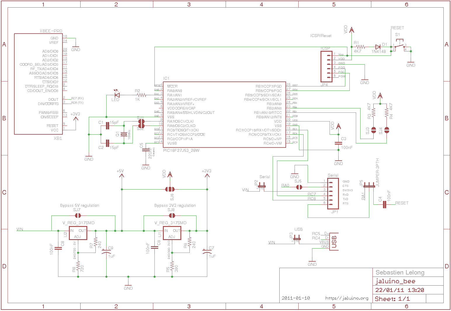
Jaluino Bee, first draft

Sebastien Lelong

mattschinkel
Although "Bee" is a good name, there may be confusion with the jallib-
pack-bee
Matt
On Jan 22, 9:33 am, Sebastien Lelong <sebastien.lel...@gmail.com>
wrote:
> 55KViewDownload

funlw65(Vasi)
Vasi
On Jan 22, 4:33 pm, Sebastien Lelong <sebastien.lel...@gmail.com>
wrote:

phalox
At GroupT (my college) we use the USB Whacker clone from sparkfun.
It's built around the 18F2553 (2bit extra ADC over 18F2550) :)
It's a nice microcontroller for experimenting stuff!
If you would keep it under 5cm², you could let it produce by
seeedstudio! They're really cheap... The only problem I had was that
there were some interconnections that shouldn't be there. But that
shouldn't happen anymore they told me :)
Good luck!!
Sebastien Lelong
It's a nice concept!
At GroupT (my college) we use the USB Whacker clone from sparkfun.
It's built around the 18F2553 (2bit extra ADC over 18F2550) :)
It's a nice microcontroller for experimenting stuff!
If you would keep it under 5cm², you could let it produce by
seeedstudio! They're really cheap... The only problem I had was that
there were some interconnections that shouldn't be there. But that
shouldn't happen anymore they told me :)
phalox
> If you want another one to have fun, have a look at 18F27J53 (though only
> support 3.3V device). You won't find so many features in one chip (including
> 12-bits ADC, USB without xtal, 2 USART, 2 MSSP, many remappable pins, RTC
> hardware, big & ram, ...
>
> http://www.microchip.com/wwwproducts/Devices.aspx?dDocName=en548695
I had a look at the prices of both microcontrollers and it seems that
yours is even cheaper! I'm thinking of proposing this one for the next
batch of boards, only the 3.3v might give some issues...
For LEDs it's not really a problem... And for now we haven't used much
more than that.
Suprising how a more advanced device can be cheaper.
> That's the idea, fit it within 5x5cm to manufacture it with Seeed. Last
> Jaluino v2.0 (and crumboard shields) were produced by seeed.
to start with SMD. I'd need to make some own PCB's...
Toon
Sebastien Lelong
That's a real nice one!I had a look at the prices of both microcontrollers and it seems that
yours is even cheaper! I'm thinking of proposing this one for the next
batch of boards, only the 3.3v might give some issues...
For LEDs it's not really a problem... And for now we haven't used much
more than that.
phalox
It's pin compatible with the 2550, it only needs some capacitors, and
a different supply.
So one pcb would make 2 nice boards... one rated at 5V, the other at
3.3
Just an idea but I think it would be very nice!
ps: ever tried to write the names of those µC delivered with the TI
launchpad?
MSP430G2211IN14
Sebastien Lelong
--
You received this message because you are subscribed to the Google Groups "jallib" group.
To post to this group, send email to jal...@googlegroups.com.
To unsubscribe from this group, send email to jallib+un...@googlegroups.com.
For more options, visit this group at http://groups.google.com/group/jallib?hl=en.
funlw65(Vasi)
If you make the LED selectable, then no pin sacrifice at all and then
no matter which pin...well, the most used peripherals must be avoided.
Anyway, what about RC2? (Digital 13 LED on FreeJALduino) - it can be a
choice also for future Pinguinos... (why not to be us the ones which
will design also the future Pinguino board - even if is named Jaluino
"code_name_here").
Vasi
On Jan 23, 2:36 pm, Sebastien Lelong <sebastien.lel...@gmail.com>
wrote:
> > .
funlw65(Vasi)
On Jan 23, 2:36 pm, Sebastien Lelong <sebastien.lel...@gmail.com>
wrote:
> LM317
> can do many voltage output, that's why I chose it, but I still wonder if
> it'll be powerful enough. In doubt, its pin layout is compatible with other
> nice regultor (fixed output voltage), like LT1117.
>
4x7segments digits or other hungry consumers - then the option to
bypass on board regulators is great. Would be better to be available
as normal jumpers...
Vasi
>
> 2011/1/23 phalox <too...@gmail.com>
>
>
>
> > Maybe take this one into your design too?
>
> > It's pin compatible with the 2550, it only needs some capacitors, and
> > a different supply.
> > So one pcb would make 2 nice boards... one rated at 5V, the other at
> > 3.3
>
> > Just an idea but I think it would be very nice!
>
> > ps: ever tried to write the names of those µC delivered with the TI
> > launchpad?
> > MSP430G2211IN14
>
> > --
> > You received this message because you are subscribed to the Google Groups
> > "jallib" group.
> > To post to this group, send email to jal...@googlegroups.com.
> > To unsubscribe from this group, send email to
> > .
Sebastien Lelong
To unsubscribe from this group, send email to jallib+un...@googlegroups.com.
--
Sebastien Lelong
To unsubscribe from this group, send email to jallib+un...@googlegroups.com.
--

vasile surducan
--
funlw65(Vasi)
On Jan 23, 4:58 pm, vasile surducan <vsurdu...@gmail.com> wrote:
> LM317 need Vin=Vout+3V to work properly.http://www.national.com/ds/LM/LM117.pdf page5
> Your schematic is redundant, why do you need two LM317 since only one VDD
> level is used (+3V3 OR +5V)?
> use the jumper on the R8, without jumper you'll have +5V, with jumper make
> R8 parallel with R8a so the equivalent resistor will be 390 and you'll have
> 3V3 at the output.
>
Vasi
> In that way you cut down three silly jumpers: SJ6, SJ7 and SJ8 and replace
> those with one.
>
> Vasile
>
> On Sat, Jan 22, 2011 at 6:33 AM, Sebastien Lelong <
>
> > .
Sebastien Lelong
> LM317 need Vin=Vout+3V to work properly.http://www.national.com/ds/LM/LM117.pdf page5
>
> Your schematic is redundant, why do you need two LM317 since only one VDD
> level is used (+3V3 OR +5V)?
> use the jumper on the R8, without jumper you'll have +5V, with jumper make
> R8 parallel with R8a so the equivalent resistor will be 390 and you'll have
> 3V3 at the output.
Your schematic is redundant, why do you need two LM317 since only one VDD level is used (+3V3 OR +5V)?use the jumper on the R8, without jumper you'll have +5V, with jumper make R8 parallel with R8a so the equivalent resistor will be 390 and you'll have 3V3 at the output.
Sebastien Lelong
On Jan 23, 4:58 pm, vasile surducan <vsurdu...@gmail.com> wrote:> LM317 need Vin=Vout+3V to work properly.http://www.national.com/ds/LM/LM117.pdf page5
Ah.... I can remember having read drop voltage was 1.3V, I must have been confused again. Thanks for pointing this. Any hint for an adjutable voltage reg like this, for replacement ?

Oliver Seitz
There are not-so-common 2.0mm jumpers that are somewhat smaller than the 0.1" types. But I for myself, I do have solder sucking wick, so solder jumpers would do for me. You can close and open them again, multiple times. I don't see it as a problem. If resistor pads were used, I'd solder a piece of wire there, no resistor. Wire is easier to remove than a real smd resistor.
For the voltage regulator, you could use an adjustable low-dropout type, like TS1117, but there are drawbacks like maximum input voltage=7V, minimum load current=10mA.
Greets,
Kiste
Sebastien Lelong
--
You received this message because you are subscribed to the Google Groups "jallib" group.
To post to this group, send email to jal...@googlegroups.com.
To unsubscribe from this group, send email to jallib+un...@googlegroups.com.
Oliver Seitz
Tantalum combines high capacity (electrolytic) with very good high-frequency performance, almost like ceramic. Instead of a tantalum, you could usually use a standard electrolytic in parallel with a ceramic, but it's two parts then.
Greets,
Kiste
funlw65(Vasi)
On Jan 24, 6:04 pm, Sebastien Lelong <sebastien.lel...@gmail.com>
wrote:
>
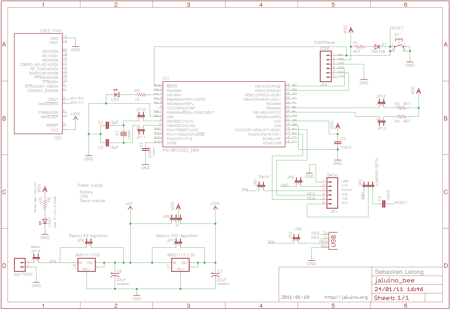
> So I'm about to change voltage regulators to dedicated ones (no more
> adjustable). I'd use AMS1117-5V and AMS1117-3.3V. These requires 22µF output
> filtering capacitors, tantalum ones. Just my curiosity: is tantalum really
> needed ? Or "standard" aluminium electrolytic ones enough ? (can be
> cheaper). I read tantalum's are smaller and more reliable. Do E-cap, C-cap,
> ... form factors (I think that's the name) often used in SMD design ? they
> I would have kept 100nF input capacitors, but datasheet doesn't mention it's
> required or recommended.
>
> I've also replaced solder jumper with "standard" PTH jumper, this way, if
> prefered, soldering a wire is still possible.
>
> Cheers,
> Seb
>
>
>
> > >Also, what do you think about having standard 0.1" pitch jumpers, usable
> > with pin headers (big but flexible), and potentially use 0805 0 ohm
> > resistors instead (small, but more definitive). I hope you understand what I
> > mean. Is it doable ? (I don't even want to ask if it's standard, but, maybe
> > there's another better/standard option).
>
> > There are not-so-common 2.0mm jumpers that are somewhat smaller than the
> > 0.1" types. But I for myself, I do have solder sucking wick, so solder
> > jumpers would do for me. You can close and open them again, multiple times.
> > I don't see it as a problem. If resistor pads were used, I'd solder a piece
> > of wire there, no resistor. Wire is easier to remove than a real smd
> > resistor.
>
> > For the voltage regulator, you could use an adjustable low-dropout type,
> > like TS1117, but there are drawbacks like maximum input voltage=7V, minimum
> > load current=10mA.
>
> > Greets,
> > Kiste
>
> > --
> > You received this message because you are subscribed to the Google Groups
> > "jallib" group.
> > To post to this group, send email to jal...@googlegroups.com.
> > To unsubscribe from this group, send email to
> > .
> >http://groups.google.com/group/jallib?hl=en.
>
> --
> Sébastien Lelonghttp://www.sirloon.nethttp://sirbot.org
>
> 60KViewDownload
Sebastien Lelong
To unsubscribe from this group, send email to jallib+un...@googlegroups.com.
--
mattschinkel
> AMS1117/3V3. Having only one component would have helped while sourcing
> them.
assume you want to input > 5v and get 3v output. If you want another
voltage you can put a jumper (just solder) to connect the input/output
of the regulator so your voltage is whatever the input is.
Matt.
Sebastien Lelong
funlw65(Vasi)
second for serial uCs. Keep 1206 smd components, otherwise you must
provide the board assembled. And this is because of 5x5mm limit. Try
to see how many features you can put on a single type of board.
Vasi
On Jan 29, 6:03 am, Sebastien Lelong <sebastien.lel...@gmail.com>
wrote:
> > > Maybe I should just use two different voltage regulator, one AMS1117/5V
> > and
> > > AMS1117/3V3. Having only one component would have helped while sourcing
> > > them.
>
> > On one prototype board I bought, there is only a AMS1117/3V3. They
> > assume you want to input > 5v and get 3v output. If you want another
> > voltage you can put a jumper (just solder) to connect the input/output
> > of the regulator so your voltage is whatever the input is.
>
> > Matt.
>
> > --
> > You received this message because you are subscribed to the Google Groups
> > "jallib" group.
> > To post to this group, send email to jal...@googlegroups.com.
> > To unsubscribe from this group, send email to
> > .
> jaluino_v03_bee_schematic.png
> 62KViewDownload
funlw65(Vasi)
Thinking at your Jaluino Medium, I found this tread:
http://www.cnczone.com/forums/attachment.php?attachmentid=85952&d=1249734850
vasile surducan
I think you will need to design two boards. One supporting USB uCs and
second for serial uCs. Keep 1206 smd components, otherwise you must
provide the board assembled. And this is because of 5x5mm limit.
Try
to see how many features you can put on a single type of board.
Vasile
To unsubscribe from this group, send email to jallib+un...@googlegroups.com.
Sebastien Lelong
funlw65(Vasi)
can be manually repositioned to have a little more space between them.
If is about 8mills traces-space then better to have them in a less
number - a reduced number of fabrication errors ...
Anyway, I like it (good to have two rows of connectors - can be
combined with male-female ones).
Vasi
On Feb 4, 11:59 am, Sebastien Lelong <sebastien.lel...@gmail.com>
wrote:
> Hi guys,
>
> >> > > .
> >> > > For more options, visit this group at
> >> > >http://groups.google.com/group/jallib?hl=en.
>
> >> > jaluino_v03_bee_schematic.png
> >> > 62KViewDownload
>
> >> --
> >> You received this message because you are subscribed to the Google Groups
> >> "jallib" group.
> >> To post to this group, send email to jal...@googlegroups.com.
> >> To unsubscribe from this group, send email to
> >> jallib+un...@googlegroups.com<jallib%2Bunsu...@googlegroups.com>
> >> .
> >> For more options, visit this group at
> >>http://groups.google.com/group/jallib?hl=en.
>
> > --
> > You received this message because you are subscribed to the Google Groups
> > "jallib" group.
> > To post to this group, send email to jal...@googlegroups.com.
> > To unsubscribe from this group, send email to
> > jallib+un...@googlegroups.com<jallib%2Bunsu...@googlegroups.com>
> > .
> > For more options, visit this group at
> >http://groups.google.com/group/jallib?hl=en.
>
> 75KViewDownload
>
> jaluino_v04_bee_pcb.png
> 43KViewDownload
>
> jaluino_v04_bee_pcb_top.png
> 33KViewDownload
>
> jaluino_v04_bee_pcb_bottom.png
> 24KViewDownload
vasile surducan
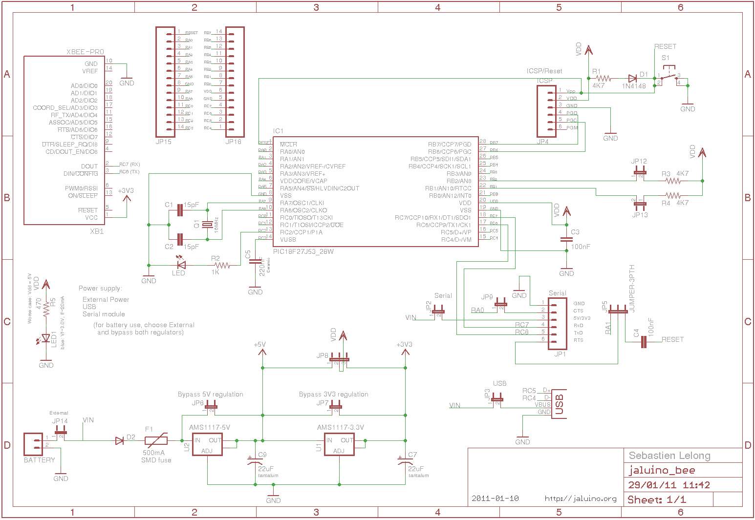
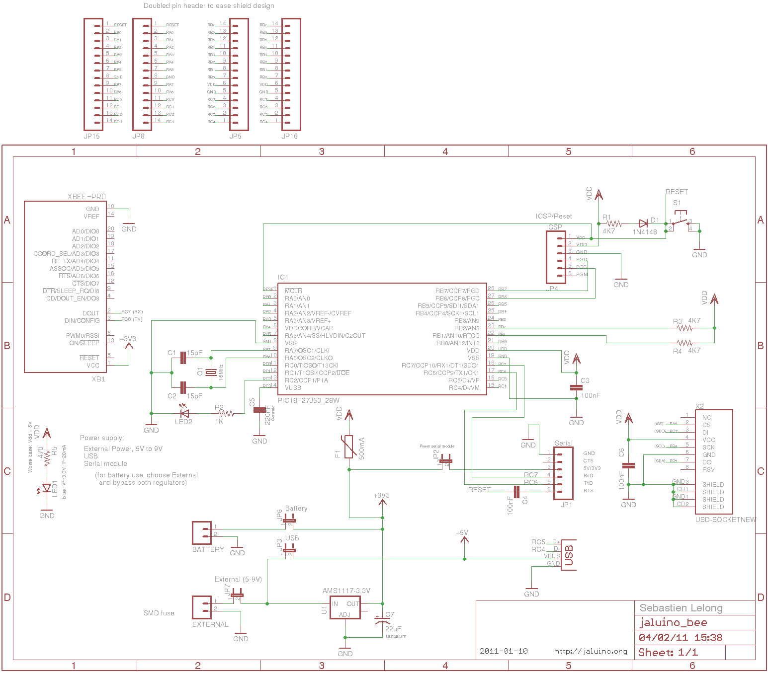
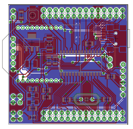
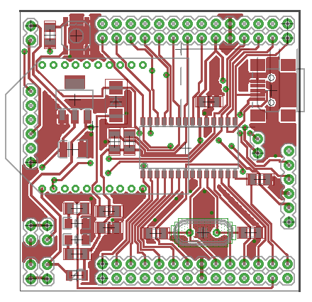
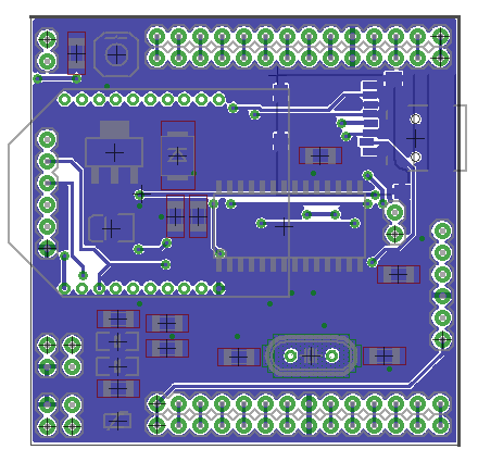
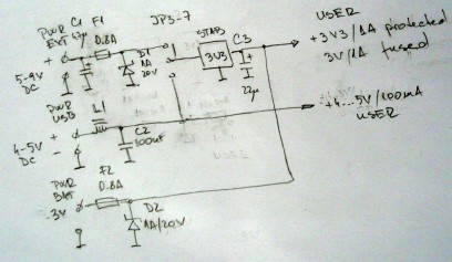
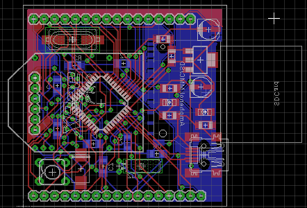
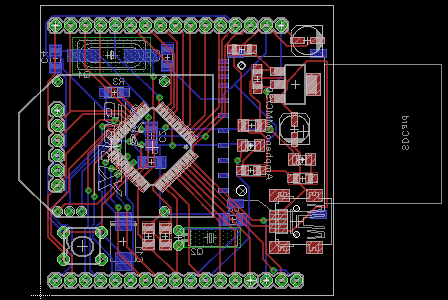
Hi guys,So...I'm back, after several tries.It was possible to keep most features, specifically providing 2 voltages, 5V and 3.3V. This was quite a mess though, mostly Xbee requires 3.3V, and possibly voltage shifter on inputs (datasheet says it's not 5V tolerant, but some report it is in reality). So I removed 5V regulation, and kept only 3.3V, making this board more 3.3V devices friendly. If Xbee isn't wanted, then one would just put an AMS1117-5V instead of 3.3V version.I worked again on power supply inputs. There can be 4 sources: USB (5V regulated to 3.3V), external (5-9V regulated to 3.3V), serial (no regulation so must output 3.3V, quite rare), and battery (direct, no regulation). I put a fuse after the regulation part.Since I had some room left, I added a microSD slot, though I still wonder how I'll solder it... :) It's on the bottom side. If replacing 3.3V regulator with a 5V one, again SD-card won't work.I doubled shield/breadboard connectors to allow breadboard + shields at the same time. User could also solder some wires to plug the board to external daughter, using external connectors/holes. Shields can also be on top or bottom, both, etc...I may also add another pin header which would include supplied voltage, making it available to shields/breadboard (voltage coming from USB, external, ...).Anyway here's the result, see attached files: schematic, PCB, PCB top, PCB bottom (some comments are wrong, sorry).Feedback appreciated. Highly !
Sebastien Lelong
To unsubscribe from this group, send email to jallib+un...@googlegroups.com.
--
Sebastien Lelong
vasile surducan
Hi Vasile,Thanks for your feedback too !Are you saying it's possible to make such a board only 20% greater than Xbee ? I could try to redesign it, but the bottleneck will pin header connectors.
Also, on my first tries, there were many many vias, and I tried to have as few as possible. Going that small will mean more vias. Is this a problem ? For instance, PIC's datasheet says caps near xtal should on the same side. I tried to respect this.
What about the fuse ? Do you think it's properly positioned ? Since there are many power source options, I can't put a fuse for each...
To unsubscribe from this group, send email to jallib+un...@googlegroups.com.
Sebastien Lelong
Also, on my first tries, there were many many vias, and I tried to have as few as possible. Going that small will mean more vias. Is this a problem ? For instance, PIC's datasheet says caps near xtal should on the same side. I tried to respect this.of course but you can use as well a SMD crystal on the micro side or on the opposite side as well
What about the fuse ? Do you think it's properly positioned ? Since there are many power source options, I can't put a fuse for each...well, I dislike your style of powering board (JP3 and JP7 both ON by mistake could kill your USB)
but that is, usually the fuse is protected by the micro or by the regulator, however one smd fuse (thermal or breackable) is enough, but I'm afraid yours will not protect something...
vasile surducan
2011/2/5 vasile surducan <vsur...@gmail.com>Also, on my first tries, there were many many vias, and I tried to have as few as possible. Going that small will mean more vias. Is this a problem ? For instance, PIC's datasheet says caps near xtal should on the same side. I tried to respect this.of course but you can use as well a SMD crystal on the micro side or on the opposite side as wellYe, I found smd crytal not so easy to find and quite expensive too. I found resonator too, but this may not be accurate enough in some cases.What about the fuse ? Do you think it's properly positioned ? Since there are many power source options, I can't put a fuse for each...well, I dislike your style of powering board (JP3 and JP7 both ON by mistake could kill your USB)I'm not happy too with this. I thought about this a lot, without good results as you can see. I could remove external source, thus removing JP7.
but that is, usually the fuse is protected by the micro or by the regulator, however one smd fuse (thermal or breackable) is enough, but I'm afraid yours will not protect something...So where do you suggest to put it ? BTW symbol is resettable but I'm planning to use "real" smd fuse.
Sebastien Lelong
I'm not happy too with this. I thought about this a lot, without good results as you can see. I could remove external source, thus removing JP7.one compromise: use a three pole jumper, either JP3 or JP7 by one move...
but that is, usually the fuse is protected by the micro or by the regulator, however one smd fuse (thermal or breackable) is enough, but I'm afraid yours will not protect something...So where do you suggest to put it ? BTW symbol is resettable but I'm planning to use "real" smd fuse.There are two unprotected power supplies: the battery which is most aggressive since a short circuit current can go higher than 500mA and the external power supply. Both USB and U1 have short circuit protected outputs. since you choose to protect only 3V3, then the logic place is in series with external battery. However, there is no reverse voltage protection neither for batter nor external power supply which is bad...

Oliver Seitz
You mean, power rails on USB connectors at a computer are short-circuit protected? This is true, but the protection is often a non-resettable SMD fuse somewhere in the middle of a very big PCB called mainboard... I'd prefer not to blow that one.
>The trouble with polarity protection (this is what we're talking about isn't ?) is the drop voltage involved with diode.
Only if you're using a diode in series. You could also use the fuse and a reasonably strong schottky diode from ground. So, reverse polarity will not go beyond 0.5V, and the fuse will blow when strong reverse power is applied.
Greets,
Kiste
Sebastien Lelong
>> Both USB and U1 have short circuit protected outputs.You mean, power rails on USB connectors at a computer are short-circuit protected? This is true, but the protection is often a non-resettable SMD fuse somewhere in the middle of a very big PCB called mainboard... I'd prefer not to blow that one.
>The trouble with polarity protection (this is what we're talking about isn't ?) is the drop voltage involved with diode.Only if you're using a diode in series. You could also use the fuse and a reasonably strong schottky diode from ground. So, reverse polarity will not go beyond 0.5V, and the fuse will blow when strong reverse power is applied.
Sebastien Lelong
Oliver Seitz
Err, I must admit that I wrote more in general... I haven't had a look at none of the schematics or drawings...
First, to clear a bit confusion:
Schottky: A diode that is usually significantly faster than silicon diodes, and has a lover voltage drop (~ 0.3V). Reverse polarity is however limited, 30V is common. There exist types that can withstand higher voltage, but the speed decreases due to the capacitance.
Zener: A silicon diode that conducts on straight polarity and insulates on reverse. But from a certain ("breakdown") voltage upward, zener diodes start conducting even in reverse polarity. This voltage is not very accurate, and there is a quite soft bend in the curve, no corner, when it starts conducting. It can be used to limit voltages, but in regulation it's usually not the best choice.
>>>The trouble with polarity protection (this is what we're talking about isn't ?) is the drop voltage involved with diode.
>>Only if you're using a diode in series. You could also use the fuse and a reasonably strong schottky diode from ground. So, reverse polarity will not go beyond 0.5V, and the fuse will blow when strong reverse power is applied.
>Thanks for the tip. Could you point to some direction about this diode ?
I was also thinking about using a schottky diode to regulate max 3.3V. I mean, according to my last power supply schematic, if user select USB but no regulation, xbee could be damaged for instance. Could a 3.3V schottky diode be used for thi purpose ? (make sure it won't be more than 3.3V ?)
A resistor+zener diode for regulation eats a lot of power. If you need 100mA at min. 3V while supply is 3.3V, the resistor can be at most 0.3V/0.1A=3 Ohm. If supply is 5.5V then while the zener diode limits to 3.3V, the resistor conducts (5.5-3.3)V/3 Ohm=733mA. That is 1.6 Watt for the resistor, and 2.5 Watt for the zener diode. Quiescent power 4 Watt. Usable as heating, but no micro electronic.
Reverse protection using fuse and "crowbar" diode: I've not seen SMD fuses below 500mA to easily come by. So I feel like protecting the computer-onboard fuse can or can not work. Even a super fast acting fuse can hold double it's rating for up to five seconds. It's pure chance which of two fuses in series will blow. To make sure which fuse blows, you would have to use one rated at most 300mA. But, reverse polarity should not be the main concern on USB, but on other inputs. A 500mA super fast fuse will blow within 5s at 1A and within 1ms at 5A. This is what the crowbar diode must cope with, only occasionally, though. SS12L could be a candidate. It is only rated 1A, but a surge current of 30A for 8ms is specified in the datasheet. It is in DO-219-AB(SMF) package, 2x3mm in size.
Whoops... Looked in a PIC datasheet. Only -0.3V are rated for PICs as absolute maximum. The SS12L will allow about 0.7V while conducting 3A. This might kill the PIC. I do know that PICs die on reverse polarity. But does anyone know if they die within milliseconds when applying only 1V in reverse?
Greets,
Kiste
vasile surducan
--
Sebastien Lelong
Sebastien Lelong
Err, I must admit that I wrote more in general... I haven't had a look at none of the schematics or drawings...
First, to clear a bit confusion:
Schottky: A diode that is usually significantly faster than silicon diodes, and has a lover voltage drop (~ 0.3V). Reverse polarity is however limited, 30V is common. There exist types that can withstand higher voltage, but the speed decreases due to the capacitance.
Zener: A silicon diode that conducts on straight polarity and insulates on reverse. But from a certain ("breakdown") voltage upward, zener diodes start conducting even in reverse polarity. This voltage is not very accurate, and there is a quite soft bend in the curve, no corner, when it starts conducting. It can be used to limit voltages, but in regulation it's usually not the best choice.
Sebastien Lelong
Sebastien Lelong

Sebastien Lelong
vasile surducan
Thanks !Why using a coil (L1 ?) with USB ?
And how it's 1A protected while using 0.8A fuse ?
So, I understand you're using 2 zener diodes 20V/1A for polarity protection, is that right ?
Sebastien Lelong
And how it's 1A protected while using 0.8A fuse ?because a 0.8A regular fuse will never blow at 0.8 A, but you need 20 years of work and 1000 fuses to know that (or a good fuse datasheet to read before starting your design)
So, I understand you're using 2 zener diodes 20V/1A for polarity protection, is that right ?you still don't know (after Oliver's message) which is difference between a zener symbol and a schottky simbol
and still trying to design board for selling, capitalist economy it's amazing ...
fortunately the buyers will don't know either those un-interesting things...
A schottky is protecting the silly user only for reversing the polarity of the power supply, by blowing the fuse if it's reversed. A zener needs a series resistor to limit the current after the voltage is increased above the zenner thresold limit.
Oliver Seitz
It takes it's time to blow a fuse. For a super fast acting SMD fuse I already gave some numbers, here a bit more detail, example is a 500mA fuse:
It will *not* blow within 1 hour at 625mA,
it will blow in less than 5 sec. at 1000mA,
it will blow in less than 1 msec. at 5A.
Some numbers for a time-lag fuse:
It will *not* blow within 4 hours at 500mA,
it will blow in less than 5 sec. at 1000mA,
at 5 A it will blow in less than 100ms, but not before 10ms.
So, if you put those two in series, only the super fast fuse will blow at very high currents, while at modest overload any of the two can blow. If you want to protect a 500mA fuse in your computer, you would have to use an external fuse rated not higher than 300mA.
There are books about connecting fuses in series :-)
Greets,
Kiste
Sebastien Lelong
--
You received this message because you are subscribed to the Google Groups "jallib" group.
To post to this group, send email to jal...@googlegroups.com.
To unsubscribe from this group, send email to jallib+un...@googlegroups.com.
For more options, visit this group at http://groups.google.com/group/jallib?hl=en.
funlw65(Vasi)
The board will be less general with the two 4k7 resistors on RB1-2...
BTW, is here a chance to have a Software SPI library?
Vasi
On Feb 6, 1:48 pm, Sebastien Lelong <sebastien.lel...@gmail.com>
wrote:
>
> Thanks for the figures. I hope not to forget them :)
>
> I had a look at last Arduino design (Uno). They use a 500mA polyfuse,
> resettable, claiming it'll add a proctection layer, in addition to the one
> included in USB host. From Jaluino Medium discussion, I understood polyfuse
> doesn't act fast enough, that's why it uses a "standard" one. This would
> make two reasons Arduino wouldn't be suitable to USB regarding fuse
> protection. Unfortunately, polyfuses remain the most interesting option:
> easy to find, small, reusable...
>
> Cheers,
> Seb
>
Sebastien Lelong
The board will be less general with the two 4k7 resistors on RB1-2...
Sebastien Lelong

funlw65(Vasi)
18F47J53... (I would like to be able tu use RTC,, useful for a SD Card
logger). Then start cutting for a smaller board as Jaluino BEE (Pinout
is very important - where is possible). So, better to start with a
10x10cm board ? ;)
Vasi
On Feb 6, 6:02 pm, Sebastien Lelong <sebastien.lel...@gmail.com>
wrote:
> MSSP2 can only be used for SPI. Since I want i²C, and SPI for embedded
> sd-card, I²C must use RB4 and RB5 pins (pullups for SDA1 and SCL1).
>
> I thus need to use different pins for SPI. MSSP2 has remappable pins (RPn
> pins on datasheets, see screenshot). Interesting feature, I'm supposed to
> select whatever remappable pins needed for SPI... Need more thoughts, but I
> think I'll remap them on RP2, RP11, RP12 and RP13.
>
> Datasheet reading.........
>
> [image: 18f27j53.png]
>
> Cheers,
> Seb
>
>
>
>
> > Hi Vasi,
>
> > 2011/2/6 funlw65(Vasi) <funl...@gmail.com>
> >> The board will be less general with the two 4k7 resistors on RB1-2...
>
> > Arf... These were supposed to be I²C pull-up resistors, but they aren't
> > connected to the correct pins ! Nice catch, thanks, I'll fix this asap ! If
> > you don't want this feature, just don't solder resistors, that's the idea.
>
> > BTW I tried to move traces and add more spaces as you suggested. I'll post
> > the result soon.
>
> > cheers,
> > Seb
>
> --
> Sébastien Lelonghttp://www.sirloon.nethttp://sirbot.org
>
> 56KViewDownload
Sebastien Lelong
Start thinking what features will have a Jaluino board with
18F47J53... (I would like to be able tu use RTC,, useful for a SD Card
logger).
Then start cutting for a smaller board as Jaluino BEE (Pinout
is very important - where is possible). So, better to start with a
10x10cm board ? ;)
--
You received this message because you are subscribed to the Google Groups "jallib" group.
To post to this group, send email to jal...@googlegroups.com.
To unsubscribe from this group, send email to jallib+un...@googlegroups.com.
For more options, visit this group at http://groups.google.com/group/jallib?hl=en.
funlw65(Vasi)
> OK I see what you mean, but I'm driven by costs. 10x10cm PCBs aren't that
> expensive, still twice the price as 5x5cm. Or, reading it on the other side,
> 5x5cm PCBs are very, very cheap. I hope to build a board for less than
> $10/$12, components + PCB all included.
http://www.adelaida.ro/product_info.php?products_id=11928&osCsid=037c0dd113d36e13790d335451ccfb12
but...
>
> PS: btw note 18f47j53 is only available on QFN package. Much harder to
> solder, would require specific equipment.
Sebastien Lelong
I think it will fit in 5x5cm with SD card but no XBEE:
http://www.adelaida.ro/product_info.php?products_id=11928&osCsid=037c0dd113d36e13790d335451ccfb12
Sebastien Lelong
A schottky is protecting the silly user only for reversing the polarity of the power supply, by blowing the fuse if it's reversed.
Sebastien Lelong
So, I understand you're using 2 zener diodes 20V/1A for polarity protection, is that right ?you still don't know (after Oliver's message) which is difference between a zener symbol and a schottky simbol and still trying to design board for selling, capitalist economy it's amazing ...fortunately the buyers will don't know either those un-interesting things...


Oliver Seitz
That's true, as long as you don't remember that a fuse has a resistance ;-) But it's usually a small drop.
>Diode should be overrated compared to the fuse, so it won't blow before the fuse.
The rating can be in the same magnitude. The schottky I was talking about is rated at 1A, but it has a surge rating of 30A for 8ms. The fuse blows within 1ms at 5A, so no danger at all for the diode.
>In this case, a resettable fuse clearly is a good choice :)
might be, but do remember to have a look at the cold resistances of polyswitch or the like, it can be several ohms.
>Since there's no voltage drop, why using Schottky diodes (since they're also less resistant) ? What not just "usual" diodes like 1N4001 (or 1N4007) ?
If you're running a strong current through a silicon diode, the voltage drop can reach 1V or a bit more. This voltage reaches the PIC as reverse supply voltage. PICs are only guaranteed to survive 0.3V reverse supply, that's why I was suggesting schottky.
Greets,
Kiste
funlw65(Vasi)
If you use only 4 pins from the XXBEE, then is good to edit the
footprint and keep only those pins, alog with other 2-3 as board
support (you still have the female socket on the board but with other
pins cut) and remove the others,, making room for traces and maybe
1206 size SMDs.
Vasi
On Feb 7, 2:47 pm, Sebastien Lelong <sebastien.lel...@gmail.com>
wrote:
> 2011/2/6 vasile surducan <vsurdu...@gmail.com>
> 2KViewDownload
>
> 250px-Schottky_diode_symbol.svg.png
> 2KViewDownload
>
> 140px-Zener_diode_symbol.svg.png
> < 1KViewDownload
Sebastien Lelong
funlw65(Vasi)
On Feb 7, 5:26 pm, Sebastien Lelong <sebastien.lel...@gmail.com>
wrote:
>
> I think I prefer keeping all socket pins, it'll be more solid, and will
> require less work to adapt. I don't think traces between Xbee scoket holes
> should be a problem, manufacturer should handle this (eagle checks and
> reports everything is fine, running seeed rules).
>
> Another point that come to me: the board is 5cm width, and is supposed to be
> breadboardable. But isn't 5cm width a little too... big for a breadboard ??
>
thinking at two independent boards :) (at least).
Also, perfboards with female connectors can be used as testing boards
for your final projects.
> Cheers,
> Seb
>
> 2011/2/7 funlw65(Vasi) <funl...@gmail.com>
funlw65(Vasi)
1. One of these:
http://www.adelaida.ro/product_info.php?products_id=8870&osCsid=7b37cf93ec215b66779dbdb93d702265
2. Two of these:
http://www.adelaida.ro/product_info.php?products_id=11585&osCsid=7b37cf93ec215b66779dbdb93d702265
3. Two of these:
http://www.adelaida.ro/product_info.php?products_id=8868&osCsid=7b37cf93ec215b66779dbdb93d702265
and so on...
Not to speaking that you can use perfboards/veroboards/stripboards of
any size....
Sebastien Lelong
Can be:
1. One of these:
http://www.adelaida.ro/product_info.php?products_id=8870I adjusted pin header so they match 0.1" space. &osCsid=7b37cf93ec215b66779dbdb93d702265
2. Two of these:
http://www.adelaida.ro/product_info.php?products_id=11I adjusted pin header so they match 0.1" space. 585&osCsid=7b37cf93ec215b66779dbdb93d702265
funlw65(Vasi)
Connections are made with isolated wires, non-isolated wires along
holes, or simply with a lot of solder... Often you use the terminals
from resistors, capacitors, ... all components you use - speaking
about a final montage.
But guys around here which greater experience can tell you more.
Personally, I prefer stripboards/veroboards.
On Feb 7, 6:55 pm, Sebastien Lelong <sebastien.lel...@gmail.com>
wrote:
>
> I adjusted pin header so they match 0.1" space for perfboard usage. BTW how
> do you use such boards, I mean, there's no trace, only holes withpads. So
> how do you connect components together ? What are the best practices ?
>
> Cheers,
> Seb
>
>
>
> > Can be:
>
> > 1. One of these:
> > header so they match 0.1" space. &osCsid=7b37cf93ec215b66779dbdb93d702265<http://www.adelaida.ro/product_info.php?products_id=8870&osCsid=7b37c...>
> > 2. Two of these:
> >http://www.adelaida.ro/product_info.php?products_id=11Iadjusted pin header
> > so they match 0.1" space. 585&osCsid=7b37cf93ec215b66779dbdb93d702265<http://www.adelaida.ro/product_info.php?products_id=11585&osCsid=7b37...>
> > 3. Two of these:
>
> >http://www.adelaida.ro/product_info.php?products_id=8868&osCsid=7b37c...
funlw65(Vasi)
in your area you have only stripboards/veroboards.
This is how to use them for a custom FreeJALduino board:
http://sites.google.com/site/funlw65/electronics/jaluino-pinguino-28-pins-starting-bo/freejalduino-on-veroboard
Or, even better, if you received a Jaluino as present, you can shield
it
with perboards/stripboards/veroboards in a very short time:
http://sites.google.com/site/funlw65/electronics/jaluino-pinguino-28-pins-starting-bo/freejalduino-stripboard-shields/pin-integrity-test-shield
On Feb 7, 7:03 pm, "funlw65(Vasi)" <funl...@gmail.com> wrote:
> I think you speak about perfboards.
> Connections are made with isolated wires, non-isolated wires along
> holes, or simply with a lot of solder... Often you use the terminals
> from resistors, capacitors, ... all components you use - speaking
> about a final montage.
>
> But guys around here which greater experience can tell you more.
> Personally, I prefer stripboards/veroboards.
>
> On Feb 7, 6:55 pm, Sebastien Lelong <sebastien.lel...@gmail.com>
> wrote:
>
> > OK, thanks.
>
> > I adjusted pin header so they match 0.1" space for perfboard usage. BTW how
> > do you use such boards, I mean, there's no trace, only holes withpads. So
> > how do you connect components together ? What are the best practices ?
>
> > Cheers,
> > Seb
>
> > 2011/2/7 funlw65(Vasi) <funl...@gmail.com>
>
> > > Can be:
>
> > > 1. One of these:
> > >http://www.adelaida.ro/product_info.php?products_id=8870Iadjustedpin
> > > header so they match 0.1" space. &osCsid=7b37cf93ec215b66779dbdb93d702265<http://www.adelaida.ro/product_info.php?products_id=8870&osCsid=7b37c...>
> > > 2. Two of these:
funlw65(Vasi)
http://www.zen22142.zen.co.uk/Prac/vero_circ/vero.htm
On Feb 7, 7:11 pm, "funlw65(Vasi)" <funl...@gmail.com> wrote:
> Let's say you want a FreeJALduino board to learn microcontrollers but
> in your area you have only stripboards/veroboards.
> This is how to use them for a custom FreeJALduino board:
>
> Or, even better, if you received a Jaluino as present, you can shield
> it
> with perboards/stripboards/veroboards in a very short time:
>
funlw65(Vasi)
Here is a very nice blog with veroboard projects (mainly Atmel):
http://txapuzas.blogspot.com/
vasile surducan
TIASeb
funlw65(Vasi)
the brains...
It seems to me that you can't use I2C, SPI and RTC same time :
( (thinking at pins used to remap the second SPI)
Here are three workarounds (target: logger applications):
1. using an external RTCC - waste.
2. using HW SPI with a SD card and I2C software - RTC on chip
3. using HW I2C and software SPI with SD card - RTC on chip.
Only the first one it appears to be reliable to me.
I don't know an ATmega with RTC but ATmega644P have 2 USART, 1 SPI, 1
I2C (TWI).. All are separated - have their own pins.
On Feb 6, 6:02 pm, Sebastien Lelong <sebastien.lel...@gmail.com>
wrote:
> MSSP2 can only be used for SPI. Since I want i²C, and SPI for embedded
> sd-card, I²C must use RB4 and RB5 pins (pullups for SDA1 and SCL1).
>
> I thus need to use different pins for SPI. MSSP2 has remappable pins (RPn
> pins on datasheets, see screenshot). Interesting feature, I'm supposed to
> select whatever remappable pins needed for SPI... Need more thoughts, but I
> think I'll remap them on RP2, RP11, RP12 and RP13.
>
> Datasheet reading.........
>
> [image: 18f27j53.png]
>
> Cheers,
> Seb
>
>
>
>
> > Hi Vasi,
>
> > 2011/2/6 funlw65(Vasi) <funl...@gmail.com>
>
>
> > Arf... These were supposed to be I²C pull-up resistors, but they aren't
> > connected to the correct pins ! Nice catch, thanks, I'll fix this asap ! If
> > you don't want this feature, just don't solder resistors, that's the idea.
>
> > BTW I tried to move traces and add more spaces as you suggested. I'll post
> > the result soon.
>
> > cheers,
> > Seb
>
> --
Sebastien Lelong
Hmmm, Microchip are designing devices thinking with their legs and not
the brains...
It seems to me that you can't use I2C, SPI and RTC same time :
( (thinking at pins used to remap the second SPI)
funlw65(Vasi)
On Feb 8, 8:45 am, Sebastien Lelong <sebastien.lel...@gmail.com>
wrote:
> 2011/2/8 funlw65(Vasi) <funl...@gmail.com>
> > Hmmm, Microchip are designing devices thinking with their legs and not
> > the brains...
>
> > It seems to me that you can't use I2C, SPI and RTC same time :
> > ( (thinking at pins used to remap the second SPI)
>
> this way).
crystal with two capacitors and for this, pins RC0 and RC1 are
occupied (so, I can keep Boot LED on RC2). On 18F46J50 is ok, more
pins so you can have also a HW SPI remapped, but not on 28pin variants
(assuming you want also de internal RTC).
>
> Seb
vasi vasi
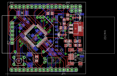
This is how it looks until now using 18F46J50 on 5x5cm board, with all major features. SD Card not yet all pins connected, board is only USB powered (I need to squeeze more space for a jumper), it use a modified footprint of XBEE PRO and I think is already at the limit, using 10 mill traces, 10 mill spaces between.
Entire schematic is just for size test (needs a pro review).
Traces are auto routed, of course...
--
Vasi
Sebastien Lelong
--
You received this message because you are subscribed to the Google Groups "jallib" group.
To post to this group, send email to jal...@googlegroups.com.
To unsubscribe from this group, send email to jallib+un...@googlegroups.com.
For more options, visit this group at http://groups.google.com/group/jallib?hl=en.
Sebastien Lelong
funlw65(Vasi)
(the cheapest one) then let it have all features possible :-) The
mother of all loggers :-)) - Made in China :-D . The 3.3V devices
power! Long live the Mother Russia!
Just kidding (well, in a technical way)
Vasi
On Feb 8, 10:45 am, Sebastien Lelong <sebastien.lel...@gmail.com>
wrote:
>
> I thought you wanted to stay from SSOP (or TQFP) package, regarding how hard
> it is to solder them. I'm not sure to understand the purpose of this design.
>
> Cheers,
> Seb
>
Oliver Seitz
>According to datasheet, RTC module can also be clocked by the INTRC oscillator.Again, no practice around this...
INTOSC has a typical accuracy of +/- 0.15%, which is about 13 hours per year, while INTRC ranges from 20.3-42,2kHz, this is 31,25 +/- 35%, or more than 8 hours per day. With this inaccuracy, I'd prefer to read the time from a random number generator :-D
32.768kHz watch crystals are small and cheap. If you want to use the RTC, don't economize in the wrong place.
Greets,
Kiste
funlw65(Vasi)
(
What said the (guppy) fish? "Damn you, Aquascan!"
Oliver Seitz
>Assuming PIC18F27J53. Why wouldn't it be possible ?
I think it will.
32.768kHz crystal on pins 11,12
I2C (MSSP1) on pins 25,26
USART1 on pins 17,18
SPI (MSSP2) and USART2 are freely remappable to the remaining 10 RPx pins.
RTCC is an (optional) output that can give the RTC input frequency, 1 pulse per second or an alarm signal.
Greets,
Kiste

Sunish Issac
Sunish
Oliver Seitz
> It seems to me that you can't use I2C, SPI and RTC same
> time :
> ( (thinking at pins used to remap the second SPI)
Can you explain a bit? Where's the collision?
Greets,
Kiste
funlw65(Vasi)
Well, Sebastien wanted to remap the SPI2 pins on pins used by the RTC
clock.and Boot LED...
I considered these:
- RP17, RP18 are occupied by RX1, TX1
- RP4 is RTC out
- RP7, RP8 is I2C1
- RP9, RP10 are part of ICSP connector
- RP11, RP12 are RTC clock
- RP13 is Boot LED (RC2) <-- other boards compatibility.
I also was conditioned by the some rules from my board (and Arduino
pinout "rules"):
- it is nice to have contiguous pins on extension connector for at
least half of a Port. (not shared with I2C, SPI, Serial) - good to use
it on LCD's by example,
- on old 19Fs you have to have some kind of order on ADC pins, because
are dependent of each other (well, not applicable here where ADC pins
are independent)
Also I had/have some unclear things:
- you said RTC Out pulse pin is optional. That mean I can disable it
without loosing RTC feature?
- when you remap pins for SPI2, it needs to be in order (RP1, RP2,
RP3, etc.), or can be selected random?
What ever is selected here on 28pin device, it propagates on the 44pin
one.
Vasi
P.S. Well, pinout compatibility was until now only FreeJALduino and
Pinguino boards care. But it will be nice also for Jaluino family.
Sebastien Lelong
Greets,
Kiste
Sebastien Lelong
He he, I think the collision is only in my head.
Well, Sebastien wanted to remap the SPI2 pins on pins used by the RTC
clock.and Boot LED...
I considered these:
- RP17, RP18 are occupied by RX1, TX1
- RP4 is RTC out
- RP7, RP8 is I2C1
- RP9, RP10 are part of ICSP connector
- RP11, RP12 are RTC clock
- RP13 is Boot LED (RC2) <-- other boards compatibility.
Also I had/have some unclear things:
- you said RTC Out pulse pin is optional. That mean I can disable it
without loosing RTC feature?
- when you remap pins for SPI2, it needs to be in order (RP1, RP2,
RP3, etc.), or can be selected random?
funlw65(Vasi)
but is not yet widely available. Which can be separate from USB family
boards.
Unfortunately, regarding to USB, Microchip is not consistent (I'm
missing very hard K50 equivalent of 2550/4550).
So, this mix of different uC's are not good for a family of boards
which try to offer some future/backward compatibility :-( (not to say
that a very bad mix is 5V - 3.3V boards - and I'm reffering at
interfacing)
>Remappable pins are getting me crazy :)
On Feb 8, 6:53 pm, Sebastien Lelong <sebastien.lel...@gmail.com>
wrote:
> 2011/2/8 funlw65(Vasi) <funl...@gmail.com>
> > He he, I think the collision is only in my head.
> > Well, Sebastien wanted to remap the SPI2 pins on pins used by the RTC
> > clock.and Boot LED...
>
> > I considered these:
>
> > - RP17, RP18 are occupied by RX1, TX1
> > - RP4 is RTC out
> > - RP7, RP8 is I2C1
> > - RP9, RP10 are part of ICSP connector
>
> these pins can still be used for other purpose when not in ICSP, right ?
changed, yes.
>
> > - RP11, RP12 are RTC clock
> > - RP13 is Boot LED (RC2) <-- other boards compatibility.
>
> There's no compatibility issue here, just use an alias...
>
compatibility (at least, this is the first thing I'm trying to solve,
where is possible).
Oliver Seitz
>- RP9, RP10 are part of ICSP connector
>these pins can still be used for other purpose when not in ICSP, right ?
You can use them for ICSP *and* for something else, you just have to make sure no electrical collision can occur. You can e.g. use them as general purpose I/O on a shield board. You just have to take off that board when reprogramming via ICSP.
>- you said RTC Out pulse pin is optional. That mean I can disable it without loosing RTC feature?
Yes. I really can hardly see any use of that function at all. You can make the ":" on a clock display blink. Great.
>>- when you remap pins for SPI2, it needs to be in order (RP1, RP2, RP3, etc.), or can be selected random?
>from what I understand, it can be whatever order you want. There are actually 2 registers per remappable pins, one for input, another four output. You then select what function to associate.
Right. Almost right. It's a bit more complicated, but in a sensible way.
For pins used as outputs, you set the *pin* to the *peripheral*.
For pins used as inputs, you set the *peripheral* to the *pin*.
This makes it possible for a peripheral to drive several output pins simultaneously. And it makes it possible for a pin to serve as input to several peripherals. It even makes it possible to connect one peripheral's output to another one's (or even its own) input with only using one pin.
Greets,
Kiste
funlw65(Vasi)
layer library?
vasi vasi
All I/O pins are connected to extension socket (exceptions are: VDDCORE, VUSB, and the main oscillator pins).
Board is powered externally only via USB, yet (it needs just a connector for other external sources).... Internal 3.3VCC is available also on extension connector.
Anyway, as is now, it is a good start for everyone to start adding/removing components and features.
--
Vasi
vasile surducan
--
Sebastien Lelong
>Remappable pins are getting me crazy :)
I said that to you long time ago :P - a first Cookoo song.
funlw65(Vasi)
On Feb 9, 7:14 am, vasile surducan <vsurdu...@gmail.com> wrote:
> Vasi,
>
> still too big PCB, distance between crystal and micro also too big, I can't
> see any filtering cap near xbee (which is must, else the RF spectrum will
> stinks),I was lazy to see how much copper did you allowed for LDO
> heatsink...
>
issues.
> However I like your design, maybe you are interested in a secondary job in
> pcb design?
>
know who will want to work with someone which designed only few
boards, it has poor knowledge and lack of experience...
I don't know if I am good for this job, but I like to design. Anyway,
I'm very slow ....
Vasi
> Vasile
vasile surducan
Hi,
I will make a decision regarding to SPI2 pins and solve the other
On Feb 9, 7:14 am, vasile surducan <vsurdu...@gmail.com> wrote:
> Vasi,
>
> still too big PCB, distance between crystal and micro also too big, I can't
> see any filtering cap near xbee (which is must, else the RF spectrum will
> stinks),I was lazy to see how much copper did you allowed for LDO
> heatsink...
>
issues.
Thank you, but you know, I started on Sebastien's base design! I don't
> However I like your design, maybe you are interested in a secondary job in
> pcb design?
>
know who will want to work with someone which designed only few
boards, it has poor knowledge and lack of experience...

Oliver Seitz
But I should warn you: I do not use those automatic via generators that some people call autorouters.
> which btw was treated so far as DC.
I do know what "short traces" means, and I usually think of DC when it's below 1MHz...
>A 20MHz square wave
Well, it's a crystal, not an oscillator, right? So it is not supposed to be square. And even if it was an oscillator, many people would be surprised when connecting a scope, how "round" a "square" can be...
Greets,
Kiste
vasile surducan
May I apply for the job? ;-)
But I should warn you: I do not use those automatic via generators that some people call autorouters.
I do know what "short traces" means, and I usually think of DC when it's below 1MHz...
> which btw was treated so far as DC.
>A 20MHz square wave
Well, it's a crystal, not an oscillator, right? So it is not supposed to be square. And even if it was an oscillator, many people would be surprised when connecting a scope, how "round" a "square" can be...
Greets,
Kiste
vasile surducan
On Thu, Feb 10, 2011 at 9:59 AM, Oliver Seitz <karl...@yahoo.com> wrote:May I apply for the job? ;-)
No, because I can't pay you at your standards.But I should warn you: I do not use those automatic via generators that some people call autorouters.
Oliver Seitz
>>May I apply for the job? ;-)
>No, because I can't pay you at your standards.
I would give you a discount ;-)
>One more idea: you can't afford to not use the autorouter when you deal with 12 layers or so and have more than 5000 joints...
Ok, that's right, but I haven't had such boards yet. But sometimes I did single-layer boards when people thought double-layer would be the minimum.
>I didn't read your post, sorry, here seems to be a new email.
I haven't wrote anything about RF yet, I just wanted to emphasize your point that anything above 1MHz is (at least can be) something to take special care of.
>>>A 20MHz square wave
>>Well, it's a crystal, not an oscillator, right? So it is not supposed to be square. And even if it was an oscillator, many people would be surprised when connecting a scope, how "round" a "square" can be...
>Yes, is round, but the oscillator output (inside the micro) is square, and the spectrum is exactly in my story...
Inside the micro there's even a 64MHz clock, no? But if supply is properly bypassed, I think we can just care about external signals. For example, the USB D+ and D- lines, that can carry 12MHz at more than 3V amplitude shouldn't be automatically routed. In Vasi's design, those lines contain forks, and are not routet in parallel next to each other. That's something I would mark for review. I would also try to avoid mapping those lines to a USB socket *and* a pin header.
Greets,
Kiste
vasile surducan
I would give you a discount ;-)
>>May I apply for the job? ;-)
>No, because I can't pay you at your standards.
Ok, that's right, but I haven't had such boards yet. But sometimes I did single-layer boards when people thought double-layer would be the minimum.
>One more idea: you can't afford to not use the autorouter when you deal with 12 layers or so and have more than 5000 joints...
I haven't wrote anything about RF yet, I just wanted to emphasize your point that anything above 1MHz is (at least can be) something to take special care of.
>I didn't read your post, sorry, here seems to be a new email.
Inside the micro there's even a 64MHz clock, no? But if supply is properly bypassed, I think we can just care about external signals. For example, the USB D+ and D- lines, that can carry 12MHz at more than 3V amplitude shouldn't be automatically routed.
>>>A 20MHz square wave
>>Well, it's a crystal, not an oscillator, right? So it is not supposed to be square. And even if it was an oscillator, many people would be surprised when connecting a scope, how "round" a "square" can be...
>Yes, is round, but the oscillator output (inside the micro) is square, and the spectrum is exactly in my story...
In Vasi's design, those lines contain forks, and are not routet in parallel next to each other. That's something I would mark for review. I would also try to avoid mapping those lines to a USB socket *and* a pin header.
