Calera -- fooling schoolchildren?

Ken Caldeira
(1) CO2 + H2O + CaCO3 --> Ca2+ + 2HCO3-
A number of authors have discussed ways to accelerate these reactions to store carbon in the ocean, neutralize carbon acidity, or both (e.g. Rau, Kheshgi. Harvey, etc). The idea of diminishing atmospheric CO2 content by dissolving carbonate minerals is discussed in the IPCC Special Report on Carbon Capture and Storage which has been reviewed by many people including prominent marine chemists. Reaction (1) is a well established net reaction involving dissolution of carbonate minerals in the ocean.
It is also well known that the formation of carbonate minerals from seawater, such as in the formation of coral skeletons, drives a flux of CO2 from the ocean to the atmosphere, essentially driving reaction (1) in reverse:
(2) Ca2+ + 2HCO3- --> CO2 + H2O + CaCO3
Furthermore, precipitating carbonates from seawater tends to lower ocean pH and thus exacerbate the ocean acidification problem.
Against this background it is surprising to see the company Calera claiming to sequester carbon dioxide by forming carbonate minerals where the cations are taken from seawater -- trying to drive the above reaction in the opposite direction to what would diminish atmospheric CO2.
Calera, in an exhibit at the California Academy of Sciences describing their process (see attachment) claim that the CO2 coming into the carbonate will be fossil fuel derived. One can only surmise that the net reaction, considering both reactor vessel and oceanic parts of this reaction can be characterized as follows
(3) CO2 + Ca2+ + 2HCO3- --> CaCO3 + H2O + 2CO2
That is, they would drive approximately two CO2 molecules into the atmosphere for each molecule they sequester. The result is that they would increase CO2 more than that which would have occurred by venting the power plant directly to the atmosphere.
So, from the publicly available information it seems that Calera's process goes in the wrong direction and will tend to increase and not decrease atmospheric CO2 content.
Furthermore, when I raised these concerns to Calera, they would not respond openly to my critique, asking me instead to sign a non disclosure agreement.
I think it is obvious to every marine geochemist that taking cations from seawater and using them to precipitate carbonate minerals will end up driving CO2 from the ocean to the atmosphere.
I call upon the California Academy of Sciences to withdraw the Calera exhibit until such time that Calera demonstrates (i) that its process does not remove cations from the ocean in a way that will ultimately drive a CO2 flux from the ocean to the atmosphere that exceeds the amount of fossil fuel stored in the carbonate mineral and (ii) that its process does not acidify the ocean.
I believe that Calera should not represent itself as having an effective carbon sequestration technique unless it responds publicly and clearly with the chemical formulas representing their process, including quantitative information on what they intend to remove from seawater and what they intend to add to seawater.
I am not sure whether Calera is ignorant or intentionally misleading, or whether they actually have a basis for their claims. If they do have a basis for their claims they should state them now. If not, the California Academy of Sciences should remove their exhibit from the museum.
I believe Calera and the Academy of Sciences are now misinforming schoolchildren, and that is not a good thing to do.
Regards,
Ken Caldeira
___________________________________________________
Ken Caldeira
Carnegie Institution Dept of Global Ecology
260 Panama Street, Stanford, CA 94305 USA
kcal...@ciw.edu; kcal...@stanford.edu
http://dge.stanford.edu/DGE/CIWDGE/labs/caldeiralab
+1 650 704 7212; fax: +1 650 462 5968
Ken Caldeira
Just to make it clear:
I am not asking Calera to tell us proprietary process information.
I am willing to treat their process as a black box, but if they are to claim that they have a real solution to this problem then they at least need to be forthcoming about what are the inputs to and outputs from their process and show us that they are not planning to violate laws of conservation of mass, energy, and electrical charge.
It is just absurd to go put a display in a museum telling schoolchildren that they have a magic process to help solve the climate-carbon problem and then refuse to tell the children when they ask what are the inputs to and outputs from that process. Science is not about "trust me". Science is about "show me". To put a display in a science museum and then say "trust me" is not teaching children how science is supposed to work.
I hope I am wrong about Calera but if they come back with a convincing story, I will be surprised indeed.
Best,
Ken
___________________________________________________
Ken Caldeira
Carnegie Institution Dept of Global Ecology
260 Panama Street, Stanford, CA 94305 USA
kcal...@ciw.edu; kcal...@stanford.edu
http://dge.stanford.edu/DGE/CIWDGE/labs/caldeiralab
+1 650 704 7212; fax: +1 650 462 5968
Ken Caldeira
Just to make it perfectly clear a non disclosure agreement covers not only proprietary technical information, but business information, plans,and usually a promise not to use the proprietary information they give you for your own business purposes. It also means they are demonstrating intent to protect their proprietary infomation. If they disclose it to one individual or entity without an NDA then they can no longer legally claim it is proprietary and someone who usurps it is not subject to legal restraint. In my own business I would never have discussions with an outsider without an NDA.I suspect you are right they are faking but to claim they are crooks or fooling schoolchildren without knowing what they have in their bag is unfair.
From: geoengi...@googlegroups.com [mailto:geoengi...@googlegroups.com] On Behalf Of Ken Caldeira
Sent: Monday, March 23, 2009 5:15 PM
To: Climate Intervention; geoengineering
Cc: Brent Constantz; John O'Donnell; Brewer, Peter; Greg Rau; Danny Harvey; Haroon Kheshgi; sst...@calacademy.org
Subject: [geo] Re: Calera -- fooling schoolchildren?
--

Dan Whaley
Besides if it's a worthy piece of engineering then one would assume they've already filed provisionals, and likely full patent filings-- at which point it would be in the public domain after 18 months anyway. If it's effectively a 'trade secret' (i.e. indefensible as non-obvious, precluded by prior art, or effectively not a process) then maybe they shouldn't be running around putting plaques up about it ...
Dan
---
Dan Whaley
CEO, Climos

jim thomas
process or something like it - with a sequestration claim attached.
Here it is with description:
WO2009006295A2: DESALINATION METHODS AND SYSTEMS THAT INCLUDE
CARBONATE COMPOUND PRECIPITATION[French]
Derwent Title: Desalinating water e.g. sea water, comprises
performing a carbonate compound precipitation process on a feed water,
and subjecting the feed water to a desalination process to produce a
desalinated product water and a waste brine [Derwent Record]
Country:
Kind: WO World Intellectual Property Organization (WIPO)
A2 Publ.of the Int.Appl. without Int.search REP. i
Inventor: CONSTANTZ, Brent; United States of America California
FARSAD, Kasra; United States of America 95123
FERNANDEZ, Miguel; United States of America 95123
Assignee: CALERA CORPORATION United States of America95032-1837
News, Profiles, Stocks and More about this company
Published / Filed: 2009-01-08 / 2008-06-27
Application Number: WO2008US0068564
IPC Code: Advanced: C04B 7/02; C04B 9/00; C04B 14/00;
Core: C04B 7/00; more...
Priority Number:
2007-06-28 US2007000937786P
2007-12-28 US2007000017392
2008-06-17 US2008000073326
Abstract: Desalination methods that include carbonate compound
precipitation are provided. In certain embodiments, feed water is
subjected to carbonate compound precipitation conditions prior to
desalination. In certain embodiments, desalination waste brine is
subjected to carbonate compound precipitation conditions. In yet other
embodiments, both feed water and waste brine are subjected to
carbonate compound precipitation conditions. Aspects of embodiments of
the invention include carbon dioxide sequestration. Embodiments of the
invention further employ a precipitate product of the carbonate
compound precipitation conditions as a building material, e.g., a
cement. Also provided are systems configured for use in methods of the
invention. [French]
Attorney, Agent or Firm: FIELD, Bret ; 1900 University Avenue, Suite
200East Palo Alto, CA 94303 94303 United States of America
Designated Country: AE AG AL AM AO AT AU AZ BA BB BG BH BR BW BY BZ
CA CH CN CO CR CU CZ DE DK DM DO DZ EC EE EG ES FI GB GD GE GH GM GT
HN HR HU ID IL IN IS JP KE KG KM KN KP KR KZ LA LC LK LR LS LT LU LY
MA MD ME MG MK MN MW MX MY MZ NA NG NI NO NZ OM PG PH PL PT RO RS RU
SC SD SE SG SK SL SM SV SY TJ TM TN TR TT TZ UA UG US UZ VC VN ZA ZM
ZW, European patent: AT BE BG CH CY CZ DE DK EE ES FI FR GB GR HR HU
IE IS IT LT LU LV MC MT NL NO PL PT RO SE SI SK TR, OAPI patent: BF BJ
CF CG CI CM GA GN GQ GW ML MR NE SN TD TG, ARIPO patent: BW GH GM KE
LS MW MZ NA SD SL SZ TZ UG ZM ZW, Eurasian patent: AM AZ BY KG KZ MD
RU TJ TM
Description:
Collapse DESALINATION METHODS AND SYSTEMS THAT INCLUDE
CARBONATE COMPOUND PRECIPITATION
CROSS-REFERENCE TO RELATED APPLICATIONS
Pursuant to 35 U.S.C. § 119 (e), this application claims priority
to the filing dates of: United States Provisional Patent Application
Serial No. 61/073,326 filed on June 17, 2008; United States
Provisional Patent Application Serial No. 60/937,786 filed on June 28,
2007 and United States Provisional Patent Application Serial No.
61.01 7,392 filed on December 28, 2007; the disclosures of which
applications are herein incorporated by reference.
INTRODUCTION
Desalination systems are desirable in many arid regions and in
marine applications where fresh water supplies are limited but large
amounts of seawater, inland waterways, rivers, or other sources of
salt containing water are available.
Fresh water is also needed in large scale for many commercial
processes, including agriculture, and electric power generation.
Most conventional desalination systems utilize reverse osmosis or
distillation processes. Both of these processes typically result in
recovery ratios of approximately 50%. Thus for every gallon of water
taken in as feed 1/2 of a gallon will become purified product water
and the other 1/2 gallon will be discharged with a brine content
approximately double in concentration of the feed water's
concentration. Discharge of this concentrated brine to the environment
can produce localized negative impacts. Conventional desalination
systems can produce a brine byproduct that is high in salts and toxic
to most organisms. Disposal of the waste brine is potentially
hazardous to the environment.
In addition, components of desalination feed waters can adversely
impact the efficiency and/or useful life of desalination systems and
components therefore. For example, in reverse osmosis systems, the
presence of divalent cations in the feed water can cause membrane
fouling or scaling, which limits the useful life of the membranes.
SUMMARY
Desalination methods that include carbonate compound precipitation
are provided. In certain embodiments, feed water is subjected to
carbonate compound precipitation conditions prior to desalination. In
certain embodiments, desalination waste brine is subjected to
carbonate compound precipitation conditions. In yet other embodiments,
both feed water and waste brine are subjected to carbonate compound
precipitation conditions. Aspects of the invention include carbon
dioxide sequestration. Embodiments of the invention further employ a
precipitate product of the carbonate compound precipitation conditions
as a building material, e.g., a cement. Also provided are systems
configured for use in methods of the invention.
BRIEF DESCRIPTION OF THE FIGURES
Figure 1 provides a flow diagram of a precipitation process
according to an embodiment of the invention.
Fig. 2 provides a graph of strength attainment results as
determined for various Portland cement blends, including blends
comprising a carbonate compound precipitate according to an embodiment
of the invention, as described in greater detail in the Experimental
Section, below.
Figures 3A to 3C provide SEM micrographs of a precipitate produced
as described in the Experimental section below.
Figure 4 provides an FTIR of a precipitate produced as described
in the Experimental section below.
DETAILED DESCRIPTION
Desalination methods that include carbonate compound precipitation
are provided. In certain embodiments, feed water is subjected to
carbonate compound precipitation conditions prior to desalination. In
certain embodiments, desalination waste brine is subjected to
carbonate compound precipitation conditions. In yet other embodiments,
both feed water and waste brine are subjected to carbonate compound
precipitation conditions. Aspects of the invention include carbon
dioxide sequestration. Embodiments of the invention further employ a
precipitate product of the carbonate compound precipitation conditions
as a building material, e.g., a cement. Also provided are systems
configured for use in methods of the invention.
Before the present invention is described in greater detail, it is
to be understood that this invention is not limited to particular
embodiments described, as such may, of course, vary. It is also to be
understood that the terminology used herein is for the purpose of
describing particular embodiments only, and is not intended to be
limiting, since the scope of the present invention will be limited
only by the appended claims.
Where a range of values is provided, it is understood that each
intervening value, to the tenth of the unit of the lower limit unless
the context clearly dictates otherwise, between the upper and lower
limit of that range and any other stated or intervening value in that
stated range, is encompassed within the invention. The upper and lower
limits of these smaller ranges may independently be included in the
smaller ranges and are also encompassed within the invention, subject
to any specifically excluded limit in the stated range. Where the
stated range includes one or both of the limits, ranges excluding
either or both of those included limits are also included in the
invention.
Certain ranges are presented herein with numerical values being
preceded by the term "about." The term "about" is used herein to
provide literal support for the exact number that it precedes, as well
as a number that is near to or approximately the number that the term
precedes. In determining whether a number is near to or approximately
a specifically recited number, the near or approximating unrecited
number may be a number which, in the context in which it is presented,
provides the substantial equivalent of the specifically recited
number.
Unless defined otherwise, all technical and scientific terms used
herein have the same meaning as commonly understood by one of ordinary
skill in the art to which this invention belongs. Although any methods
and materials similar or equivalent to those described herein can also
be used in the practice or testing of the present invention,
representative illustrative methods and materials are now described.
All publications and patents cited in this specification are
herein incorporated by reference as if each individual publication or
patent were specifically and individually indicated to be incorporated
by reference and are incorporated herein by reference to disclose and
describe the methods and/or materials in connection with which the
publications are cited. The citation of any publication is for its
disclosure prior to the filing date and should not be construed as an
admission that the present invention is not entitled to antedate such
publication by virtue of prior invention.
Further, the dates of publication provided may be different from
the actual publication dates which may need to be independently
confirmed.
It is noted that, as used herein and in the appended claims, the
singular forms "a", "an", and "the" include plural referents unless
the context clearly dictates otherwise. It is further noted that the
claims may be drafted to exclude any optional element. As such, this
statement is intended to serve as antecedent basis for use of such
exclusive terminology as "solely," "only" and the like in connection
with the recitation of claim elements, or use of a "negative"
limitation.
As will be apparent to those of skill in the art upon reading this
disclosure, each of the individual embodiments described and
illustrated herein has discrete components and features which may be
readily separated from or combined with the features of any of the
other several embodiments without departing from the scope or spirit
of the present invention. Any recited method can be carried out in the
order of events recited or in any other order which is logically
possible.
METHODS
As summarized above, aspects of the invention include desalination
method, where an aspect of the methods is that a carbonate compound
precipitation process is performed at one or more times during the
overall desalination protocol, e.g., where the feed water and/or waste
brine is subjected to carbonate compound precipitation conditions.
Embodiments of the methods include: (a) subjecting a feed water to
carbonate compound precipitation conditions one or more times to
produce a carbonate compound precipitate and an
alkali-earth-metal-ion-depleted water; and (b) desalinating the
alkali-earth-metal-ion-depleted water to produce a product water.
Embodiments of the methods include: a) desalinating salt water to
produce desalinated water and waste brine; b) subjecting the waste
brine to mineral precipitation conditions to produce a precipitated
mineral composition and depleted (i.e., treated) brine; and c)
separating the mineral composition from said depleted brine. In
certain embodiments, these steps may involve several sequential
processes of step a - c, resulting in near zero, or discharge
following the processing.
In certain of the above embodiments, the methods include charging
the water with carbon dioxide from an exogenous source, such as the
flue gases from and electrical power plant, to increase the efficiency
and yield of the process.
The salt water that is desalinated in embodiments of the invention
may be from any convenient saltwater source. The term "saltwater" is
employed in its conventional sense to refer a number of different
types of aqueous fluids other than fresh water, where the term
"saltwater" includes brackish water, sea water and brine (including
man-made brines, e.g., geothermal plant wastewaters, etc), as well as
other salines having a salinity that is greater than that of
freshwater. Brine is water saturated or nearly saturated with salt and
has a salinity that is 50 ppt (parts per thousand) or greater.
Brackish water is water that is saltier than fresh water, but not as
salty as seawater, having a salinity ranging from 0.5 to 35 ppt.
Seawater is water from a sea or ocean and has a salinity ranging from
35 to 50 ppt. The saltwater source from which the saltwater feedwater
is obtained may be a naturally occurring source, such as a sea, ocean,
lake, swamp, estuary, lagoon, etc., or a man-made source. In certain
embodiments, the saltwater source is an ocean or sea and the saltwater
feedwater is seawater. Saltwaters of interest are ones which contain
one or more alkaline earth metals, e.g., magnesium, calcium, etc, such
that they may be viewed as alkaline-earth-metal-containing waters.
Examples of such waters are those that include calcium in amounts
ranging from 50 ppm to 20,000 ppm, such as 200 ppm to 5000 ppm and
including 400 ppm to 1000 ppm. Waters of interest include those that
include magnesium in amounts ranging from 50 ppm to 40,000 ppm, such
as 100 ppm to 10,000 ppm and including 500 ppm to 2500 ppm.
Any convenient protocol may be employed in desalinating saltwater.
Desalination (i.e., desalinization or desalinization) refers to
any of several processes that remove excess salt and other minerals
from water. In desalination, water is desalinated in order to be
converted to fresh water suitable for animal consumption or
irrigation, or, if almost all of the salt is removed, for human
consumption.
Desalination methods of interest include, but are not limited to:
distillation methods, e.g., Multi-stage flash distillation (MSF),
Multiple-effect evaporator (MED|ME), Vapor-compression evaporation
(VC) and Evaporation/condensation; Ion exchange methods; Membrane
processes, e.g., Electrodialysis reversal (EDR), Reverse osmosis (RO),
Nanofiltration (NF), Forward osmosis (FO), Membrane distillation (MD);
etc.
As summarized above, at some point during the overall desalination
process, e.g., before and/or after desalination, a carbonate compound
precipitation step is performed, such that a water is subjected to
carbonate compound precipitation conditions. As such, a feedwater
and/or waste brine of the desalination process is subjected carbonate
compound precipitation conditions. Carbonate precipitation conditions
of interest include contacting a water of interest, e.g., feedwater
and/or waste brine, with CO2 to produce a CO2 charged water and then
subjecting the CO2 charged water to carbonate compound precipitation
conditions.
Contact of the water with the source CO2 may occur before and/or
during the time when the water is subject to CO2 precipitation
conditions, e.g., as described in greater detail below. Accordingly,
embodiments of the invention include methods in which the volume of
water is contacted with a source of CO2 prior to subjecting the volume
of water to precipitation conditions. Embodiments of the invention
include methods in which the volume of water is contacted with a
source of CO2 while the volume of water is being subjected to
carbonate compound precipitation conditions.
Embodiments of the invention include methods in which the volume
of water is contacted with a source of a CO2 both prior to subjecting
the volume of water to carbonate compound precipitation conditions and
while the volume of water is being subjected to carbonate compound
precipitation conditions.
The source of CO2 that is contacted with the volume of water in
these embodiments may be any convenient CO2 source. The CO2 source may
be a liquid, solid (e.g., dry ice) or gaseous CO2 source. In certain
embodiments, the CO2 source is a gaseous CO2 source. This gaseous CO2
may vary widely, ranging from air, industrial waste streams, etc. This
gaseous CO2 is, in certain instances, a waste product from an
industrial plant. The nature of the industrial plant may vary in these
embodiments, where industrial plants of interest include power plants,
chemical processing plants, and other industrial plants that produce
CO2 as a byproduct. By waste stream is meant a stream of gas (or
analogous stream) that is produced as a byproduct of an active process
of the industrial plant, e.g., an exhaust gas. The gaseous stream may
be substantially pure CO2 or a multi-component gaseous stream that
includes CO2 and one or more additional gases. Multi-component gaseous
streams (containing CO2) that may be employed as a CO2 source in
embodiments of the subject methods include both reducing, e.g.,
syngas, shifted syngas, natural gas, and hydrogen and the like, and
oxidizing condition streams, e.g., flue gases from combustion.
Particular multi-component gaseous streams of interest that may be
treated according to the subject invention include: oxygen containing
combustion power plant flue gas, turbo charged boiler product gas,
coal gasification product gas, shifted coal gasification product gas,
anaerobic digester product gas, wellhead natural gas stream, reformed
natural gas or methane hydrates, and the like.
In embodiments of the invention, the CO2 source may be flue gas
from coal or other fuel combustion, which is contacted with the volume
of saltwater with little or no pretreatment of the flue gas. In these
embodiments, the magnesium and calcium ions in the
alkali-earth-metal-containing water react to form CaSO4 and MgSO4 and
other compounds, as well as CaCO3 and MgCO3 and other compounds,
effectively removing sulfur from the flue gas stream without
additional release of CO2 from the desulfurization step. In certain
embodiments, the desulfurization step may be staged to coincide with
the carbonate compound precipitation step, or may be staged to occur
before this step. In certain embodiments therefore there are multiple
sets of reaction products collected at different stages, while in
other embodiments there is a single reaction product collected.
In addition to magnesium and calcium containing products of the
precipitation reaction, compounds of interest include those based on
silicon, aluminum, iron, boron and other elements. Chemical
composition and morphology of the products resulting from use of these
reactants may alter reactivity of cements resulting from the process,
or change the nature of the properties of cured cements and concretes
made from them. In embodiments of the invention, ash (as described in
greater detail below) is added to the reaction as one source of these
additional reactants, to produce carbonate mineral precipitates which
contain one or more components such as amorphous silica, crystalline
silica, calcium silicates, calcium alumina silicates, or any other
moiety which may result from the reaction of ash in the carbonate
mineral precipitation process.
The volume of water may be contacted with the CO2 source using any
convenient protocol. Where the CO2 is a gas, contact protocols of
interest include, but are not limited to: direct contacting protocols,
e.g., bubbling the gas through the volume of saltwater, concurrent
contacting means, i.e., contact between unidirectionally flowing
gaseous and liquid phase streams, countercurrent means, i.e., contact
between oppositely flowing gaseous and liquid phase streams, and the
like. Thus, contact may be accomplished through use of infusers,
bubblers, fluidic Venturi reactor, sparger, gas filter, spray, tray,
or packed column reactors, and the like, as may be convenient.
In methods of the invention, a volume of CO2 charged water, e.g.,
produced as described above, is subjected to carbonate compound
precipitation conditions sufficient to produce a precipitated
carbonate compound composition and an alkaline-earth metal depleted
water, which in the context of the precipitation step may be viewed as
the mother liquor (i.e., the part of the water that is left over after
precipitation of the carbonate compound composition from the water).
Any convenient precipitation conditions may be employed, which
conditions result in the production of a carbonate-containing solid or
precipitate from the CO2 charged water.
Precipitation conditions of interest include those that modulate
the physical environment of the CO2 charged water to produce the
desired precipitate product.
For example, the temperature of the CO2 charged may be raised to
an amount suitable for precipitation of the desired carbonate compound
to occur. In such embodiments, the temperature of the CO2 charged may
be raised to a value from 5 to 70QC, such as from 20 to 50QC and
including from 25 to 45QC. As such, while a given set of precipitation
conditions may have a temperature ranging from 0 to 100 QC, the
temperature may be raised in certain embodiments to produce the
desired precipitate. In certain embodiments, the temperature is raised
using energy generated from low or zero carbon dioxide emission
sources, e.g., solar energy source, wind energy source, hydroelectric
energy source, etc. In certain embodiments the temperature may be
raised utilizing heat from flue gases from coal or other fuel
combustion.
Aspects of the invention include raising the pH of the CO2 charged
water to alkaline levels for precipitation. The pH may be raised to 9
or higher, such as 10 or higher, e.g., 11 or higher.
In embodiments of the invention, ash is employed as a pH modifying
agent, e.g., to increase the pH of the CO2 charged water. The ash may
be used as a as the sole pH modifier or in conjunction with one or
more additional pH modifiers.
Of interest in certain embodiments is use of a coal ash as the
ash. The coal ash as employed in this invention refers to the residue
produced in power plant boilers or coal burning furnaces, for example,
chain grate boilers, cyclone boilers and fluidized bed boilers, from
burning pulverized anthracite, lignite, bituminous or sub-bituminous
coal. Such coal ash includes fly ash which is the finely divided coal
ash carried from the furnace by exhaust or flue gases; and bottom ash
which collects at the base of the furnace as agglomerates. Use of
ashes as an alkaline source is further described in United States
Provisional Application 61/073,31 9 filed on June 17, 2008, the
disclosure of which is herein incorporated by reference.
In embodiments of the invention, slag is employed as a pH
modifying agent, e.g., to increase the pH of the CO2 charged water.
The slag may be used as a as the sole pH modifier or in conjunction
with one or more additional pH modifiers. Slag is generated from the
processing of metals, and may contain calcium and magnesium oxides as
well as iron, silicon and aluminum compounds. The use of slag as a pH
modifying material may provide additional benefits via the
introduction of reactive silicon and alumina to the precipitated
product. Slags of interest include, but are not limited to, blast
furnace slag from iron smelting, slag from electric-arc or blast
furnace processing of steel, copper slag, nickel slag and phosphorus
slag.
In certain embodiments, a pH raising agent may be employed, where
examples of such agents include oxides, hydroxides (e.g., calcium
oxide, potassium hydroxide, sodium hydroxide, brucite (Mg(OH2), etc.
), carbonates (e.g., sodium carbonate), serpentine, chrysotile, and
the like. The addition of serpentine, also releases silica and
magnesium into the solution, leading to the formation of silica
containing carbonate compounds. The amount of pH elevating agent that
is added to the water will depend on the particular nature of the
agent and the volume of water being modified, and will be sufficient
to raise the pH of the water to the desired value. Alternatively, the
pH of the water can be raised to the desired level by electrolysis of
the water. Where electrolysis is employed, a variety of different
protocols may be taken, such as use of the Mercury cell process (also
called the Castner-Kellner process); the Diaphragm cell process and
the membrane cell process. Where desired, byproducts of the hydrolysis
product, e.g., H2, sodium metal, etc. may be harvested and employed
for other purposes, as desired. In certain embodiments, the pH level
of the carbonate precipitation supernatant is increased via
electrolysis and then returned to the reaction vessel along with
seawater or desalination brine to participate in further carbonate
precipitation. The removal of calcium, magnesium and other cations in
these embodiments prior to electrolysis can make using the
electrolysis process to raise the solution pH more efficient Additives
other than pH elevating agents may also be introduced into the water
in order to influence the nature of the precipitate that is produced.
As such, certain embodiments of the methods include providing an
additive in water before or during the time when the water is
subjected to the precipitation conditions. Certain calcium carbonate
polymorphs can be favored by trace amounts of certain additives.
For example, vaterite, a highly unstable polymorph of CaCO3 which
precipitates in a variety of different morphologies and converts
rapidly to calcite, can be obtained at very high yields by including
trace amounts of lanthanum as lanthanum chloride in a supersaturated
solution of calcium carbonate. Other additives beside lathanum that
are of interest include, but are not limited to transition metals and
the like. For instance, the addition of ferrous or ferric iron is
known to favor the formation of disordered dolomite (protodolomite)
where it would not form otherwise.
In certain embodiments, additives are employed which favor the
formal of precipitates characterized by larger sized particles, e.g.,
particles ranging in size from 50 to 1000 µm, such as 100 to 500µm,
and/or of an amorphous nature. In certain embodiments, these additives
are transition metal catalysts. Transition metal catalysts of interest
include, but are not limited to: soluble compounds of Zn, Cr, Mn, Fe,
Co, and Ni or any combination thereof. Specific compounds of interest
include, but are not limited to: CoCI2 or NiCI2. The amount of such
transition metal catalysts, when employed, may vary, ranging in
certain embodiments fromi Oppb to 2000 ppm, such as 100 ppb to 500ppm.
Inclusions of such additives may be employed to provide for amorphous
products where otherwise crystalline products are obtained without
such additives and/or to obtain larger particle sizes in the
precipitate as compared to precipitates produced in the absence of
such additives.
The nature of the precipitate can also be influenced by selection
of appropriate major ion ratios. Major ion ratios also have
considerable influence of polymorph formation. For example, as the
magnesiunrcalcium ratio in the water increases, aragonite becomes the
favored polymorph of calcium carbonate over low- magnesium calcite. At
low magnesiunrcalcium ratios, low-magnesium calcite is the preferred
polymorph.
Rate of precipitation can also be modulated to control the nature
of the compound phase formation. The most rapid precipitation can be
achieved by seeding the solution with a desired phase. Without
seeding, rapid precipitation can be achieved by rapidly increasing the
pH of the sea water, which results in more amorphous constituents.
When silica is present, the more rapid the reaction rate, the more
silica is incorporated with the carbonate precipitate. The higher the
pH is, the more rapid the precipitation is and the more amorphous the
precipitate is. In certain embodiments, the rate of precipitation is
chosen to produce large aragonite crystals of higher purity, e.g.,
crystals of agglomerated structures ranging from 20 to 50 µm, made up
of individual structures ranging from 10 to 15µm, e.g., as described
in Example II, below.
Accordingly, a set of precipitation conditions to produce a
desired precipitate from a water include, in certain embodiments, the
water's temperature and pH, and in some instances the concentrations
of additives and ionic species in the water.
Precipitation conditions may also include factors such as mixing
rate, forms of agitation such as ultrasonics, and the presence of seed
crystals, catalysts, membranes, or substrates. In some embodiments,
precipitation conditions include supersaturated conditions,
temperature, pH, and/or concentration gradients, or cycling or
changing any of these parameters. The protocols employed to prepare
carbonate compound precipitates according to the invention may be
batch or continuous protocols. It will be appreciated that
precipitation conditions may be different to produce a given
precipitate in a continuous flow system compared to a batch system.
Following production of the carbonate compound precipitate from
the water, the resultant precipitated carbonate compound composition
is separated from the mother liquor to produce a product water, e.g.,
alkaline-earth-metal-depleted water that can be used for feedwater for
desalination or treated brine. Separation of the precipitate from the
product water can be achieved using any convenient approach, including
a mechanical approach, e.g., where bulk excess water is drained from
the precipitate, e.g., either by gravity alone or with the addition of
vacuum, mechanical pressing, by filtering the precipitate from the
mother liquor to produce a filtrate, etc.
Separation of bulk water produces a wet, dewatered precipitate.
In certain filtration embodiments, the size of the precipitate
particles are controlled to provide for efficient and non-energy
intensive filtration, e.g., where precipitated particles are produced
having a size ranging from 50 to 1000 µm, such as 100 to 500 µm. As
such, in some embodiments of the current invention, the size and
composition of the precipitated material is controlled to reduce or
eliminate the need for high energy mechanical filtration of the
feedstock prior to reverse osmosis.
With the use of certain transition metal catalysts in carbonate
and carbonate/silicate precipitation processes, it is possible to
attain amorphous precipitates where crystalline structures are
typically observed. The transition metal catalysts that can be used
comprise soluble compounds of Zn, Cr, Mn, Fe, Co, and Ni or any
combination of. For instance, CoCI2 or NiCI2 added at concentration
anywhere from 10 ppb to 2000 ppm, including I OOppb to 500ppm, will
result in the precipitation of an amorphous structure where a
completely crystalline structure would typically be observed.
The rate of formation of the precipitate is enhanced by the use of
these catalysts, resulting in a larger particle size, a more amorphous
structure, or a combination thereof. In those embodiments producing
larger particle sizes, the removal of the precipitate from the
feedstock can be accomplished by lower energy means, such as gravity
settling.
In contrast with seeding approaches to precipitation, methods of
invention do not generate CO2 during the precipitation process. As
such, embodiments of methods of the invention may be viewed as
CO2-generation-free precipitation protocols.
Figure 1 provides a schematic flow diagram of a carbonate
precipitation process according to an embodiment of the invention. In
Figure 1, water from a water source 10, which may be feedwater for a
desalination plant and/or waste brine from a desalination plant, is
subjected to carbonate compound precipitation conditions at
precipitation step 20. In the embodiment depicted in Figure 1, the
water from water source 10 is first charged with CO2 to produce CO2
charged water, which CO2 is then subjected to carbonate compound
precipitation conditions. As depicted in Figure 1, a CO2 gaseous
stream 30 is contacted with the water at precipitation step 20. The
provided gaseous stream 30 is contacted with a suitable water at
precipitation step 20 to produce a CO2 charged water, as reviewed
above. At precipitation step 20, carbonate compounds, which may be
amorphous or crystalline, are precipitated. As reviewed above, CO2
charging and carbonate compound precipitation may occur in a
continuous process or at separate steps. As such, charging and
precipitation may occur in the same reactor of a system, e.g., as
illustrated in Figure 1 at step 20, according to certain embodiments
of the invention.
In yet other embodiments of the invention, these two steps may
occur in separate reactors, such that the water is first charged with
CO2 in a charging reactor and the resultant CO2 charged water is then
subjected to precipitation conditions in a separate reactor.
Following production of the carbonate precipitate from the water,
the resultant precipitated carbonate compound composition is separated
from the alkaline-earth- metal-depleted water, i.e., the mother
liquor, to produce separated carbonate compound precipitate product,
as illustrated at step 40 of Figure 1. Separation of the precipitate
can be achieved using any convenient approach, including a mechanical
approach, e.g., where bulk excess water is drained from the
precipitated, e.g., either by gravity alone or with the addition of
vacuum, mechanical pressing, by filtering the precipitate from the
mother liquor to produce a filtrate, etc. Separation of bulk water
(which is to be employed as treated feed water for desalination or
treated brine, as described above and indicated as 42) produces a wet,
dewatered precipitate.
In the embodiment shown in Figure 1, the resultant dewatered
precipitate is then dried to produce a product, as illustrated at step
60 of Figure 1. Drying can be achieved by air drying the filtrate.
Where the filtrate is air dried, air drying may be at room or elevated
temperature. In yet another embodiment, the precipitate is spray dried
to dry the precipitate, where the liquid containing the precipitate is
dried by feeding it through a hot gas (such as the gaseous waste
stream from the power plant), e.g., where the liquid feed is pumped
through an atomizer into a main drying chamber and a hot gas is passed
as a co-current or counter-current to the atomizer direction.
Depending on the particular drying protocol of the system, the drying
station may include a filtration element, freeze drying structure,
spray drying structure, etc. Where desired, the dewatered precipitate
product from the separation reactor 40 may be washed before drying, as
illustrated at optional step 50 of Figure 1. The precipitate may be
washed with freshwater, e.g., to remove salts (such as NaCI) from the
dewatered precipitate. Used wash water may be disposed of as
convenient, e.g., by disposing of it in a tailings pond, etc. In
certain embodiments, the resultant product is further processed, e.g.,
to produce an above ground storage stable carbon sequestration
material, to produce a building material, etc., as described in
greater detail below. For example, in the embodiment illustrated in
Figure 1, at step 70, the dried precipitate is further processed or
refined, e.g., to provide for desired physical characteristics, such
as particle size, surface area, etc., or to add one or more components
to the precipitate, such as admixtures, aggregate, supplementary
cementitious materials, etc., to produce a final product 80.
In certain embodiments, a system is employed to perform the above
methods, where such systems include those described below in greater
detail.
The product water of the process illustrated in Figure 1, i.e.,
the alkaline- earth-metal-depleted water, is either subjected to
desalination and/or disposed of in a suitable manner, e.g., depending
on whether the input water of the carbonate compound precipitation
reaction is feedwater or waste brine, as indicated by element 42.
In those embodiments where input water of the carbonate compound
precipitation process is desalination feedwater, the product
alkaline-earth-metal- depleted water is then subjected to a
desalination process. As reviewed above, any convenient protocol may
be employed in desalinating saltwater. Desalination (i.e.,
desalinization or desalinization) refers to any of several processes
that remove excess salt and other minerals from water. In
desalination, water is desalinated in order to be converted to fresh
water suitable for animal consumption or irrigation, or, if almost all
of the salt is removed, for human consumption. Desalination methods of
interest include, but are not limited to: distillation methods, e.g.,
Multi-stage flash distillation (MSF), Multiple-effect evaporator
(MED|ME), Vapor-compression evaporation (VC) and
Evaporation/condensation; Ion exchange methods; Membrane processes,
e.g., Electrodialysis reversal (EDR), Reverse osmosis (RO),
Nanofiltration (NF), Forward osmosis (FO), Membrane distillation (MD);
etc.
Of interest in certain embodiments are membrane desalination
processes, e.g., reverse osmosis. Reverse osmosis (RO) is a separation
process that uses pressure to force a feedwater through a membrane(s)
that retains a solute(s) on one side and allows water molecules to
pass to the other side. As such, it is the process of forcing water
molecules from a region of high solute concentration through a
membrane to a region of low solute concentration by applying a
pressure in excess of the osmotic pressure. Membranes employed in RO
processes are semipermeable, such that they allow the passage of water
but not of solute(s). The membranes used for reverse osmosis have a
dense barrier layer in the polymer matrix where most separation
occurs. In certain embodiments, the membrane is designed to allow only
water to pass through this dense layer while preventing the passage of
solutes (such as salt ions). Embodiments of RO employ a high pressure
that is exerted on the high concentration side of the membrane, such
as 2-1 7 bar (30-250 psi) for brackish water, and 40-70 bar (600-1 000
psi) for seawater. RO processes and systems with which the present
invention may be employed include, but are not limited to, those
described in U.S. Patent Nos.: 6,833,073; 6,821 ,430; 6,709,590;
6,656,362; 6,537,456; 6,368,507; 6,245,234; 6,1 90,556; 6,1 87,200;
6,1 56,680; 6,1 39,740; 6,1 32,61 3; 6,063,278; 6,01 5,495; 5,925,255;
5,851 ,355; 5,593,588 ; 5,425,877; 5,358,640; 5,336,409; 5,256,303;
5,250,1 85; 5,246,587; 5,1 73,335 ; 5,1 60,61 9; RE34,058; 5,084,1 82;
5,01 9,264; 4,988,444; 4,886,597; 4,772,391 ; 4,702,842; 4,473,476;
4,452,696; 4,341 ,629 ; 4,277,344; 4,259,1 83; the disclosures of
which are herein incorporated by reference.
As summarized above, in certain embodiments the water subjected to
carbonate compound precipitation conditions is a waste brine.
Desalinating salt water produces desalinated water and waste brine.
The desalinated water may be further employed in any convenient
manner, e.g., for irrigation, for animal and human consumption, for
industrial use, etc.
Waste brine produced by desalination is then processed to produce
treated brine. In the subject methods, the waste brine is subjected to
carbonate compound precipitation conditions, as described above. In
some cases, it may be desirable to remove the chloride and sodium from
the initial brine concentrate before the brine is treated to produce
depleted brine. For instance, following the initial desalting step
where freshwater is produced, and the initial brine concentrate is
formed, chlorine, caustic soda, and halite (table salt) may be
produced via a chlor-alkali process or the like, before the carbonate
and hydroxide minerals are precipitated from the brine. In these
cases, a near-zero, or zero discharge depleted brine, of only fresh,
or near- fresh water is produced.
Following production of the precipitate from the waste brine, the
resultant precipitate is separated from the remaining liquid, which is
referred to herein as treated or depleted brine. Separation of the
precipitate can be achieved as described above. The resultant treated
brine may then be further processed and/or returned to the environment
as desired. For example, the treated brine may be returned to the
source of the water, e.g., ocean, or to another location. In certain
embodiments, the treated brine may be contacted with a source of CO2,
e.g., as described above, to sequester further CO2. For example, where
the treated brine is to be returned to the ocean, the treated brine
may be contacted with a gaseous source of CO2 in a manner sufficient
to increase the concentration of carbonate ion present in the treated
brine. Contact may be conducted using any convenient protocol, such as
those described above. In certain embodiments, the treated brine has
an alkaline pH, and contact with the CO2 source is carried out in a
manner sufficient to reduce the pH to a range between 5 and 9, e.g., 6
and 8.5, including 7.5 to 8.2.
The resultant treated brine of the reaction may be disposed of
using any convenient protocol. In certain embodiments, it may be sent
to a tailings pond for disposal. In certain embodiments, it may be
disposed of in a naturally occurring body of water, e.g., ocean, sea,
lake or river. In certain embodiments, the treated brine is returned
to the source of feedwater for the desalination process, e.g., an
ocean or sea.
Practice of the methods of the invention results in the production
of a carbonate containing precipitate product. As the precipitates are
derived from a water source, they will include one or more components
that are present in the water source, e.g., sea water, brine, brackish
water, and identify the compositions that come from the water source,
where these identifying components and the amounts thereof are
collectively referred to herein as a water source identifier. For
example, if the water source is sea water, identifying compounds that
may be present in the carbonate compound compositions include, but are
not limited to: chloride, sodium, sulfur, potassium, bromide, silicon,
strontium and the like. Any such source- identifying or "marker"
elements are generally present in small amounts, e.g., in amounts of
20,000 ppm or less, such as amounts of 2000 ppm or less. In certain
embodiments, the "marker" compound is strontium, which may be present
in the precipitated incorporated into the aragonite lattice, and make
up 10,000 ppm or less, ranging in certain embodiments from 3 to 10,000
ppm, such as from 5 to 5000 ppm, including 5 to 1000 ppm, e.g., 5 to
500 ppm, including 5 to 100 ppm. Another "marker" compound of interest
is magnesium, which may be present in amounts of up to 20% mole
substitution for calcium in carbonate compounds. The saltwater source
identifier of the compositions may vary depending on the particular
saltwater source employed to produce the saltwater-derived carbonate
composition. In certain embodiments, the calcium carbonate content of
the cement is 25% w/w or higher, such as 40 % w/w or higher, and
including 50% w/w or higher, e.g., 60% w/w. The carbonate compound
composition has, in certain embodiments, a calcium/magnesium ratio
that is influenced by, and therefore reflects, the water source from
which it has been precipitated. In certain embodiments, the
calcium/magnesium molar ratio ranges from 10/1 to 1/5 Ca/Mg, such as
5/1 to 1/3 Ca/Mg. In certain embodiments, the carbonate composition is
characterized by having an water source identifying carbonate to
hydroxide compound ratio, where in certain embodiments this ratio
ranges from 100 to 1, such as 10 to 1 and including 1 to 1.
In certain embodiments, the product precipitate may include one or
more boron containing compounds. Boron containing compounds that may
be present include, but are not limited to: boric acid; borates and
borate polymers, e.g., Borax (i.e., sodium borate, sodium tetraborate,
or disodium tetraborate), Colemanite (CaB3O4(OH)3 H2O); Admontite (or
Admontit or Admontita (MgB 6O10-7H2O)); etc. In addition, the
precipitates may include organics, e.g., polyacrylic acid,
trihalomethane precursors, pesticides, algae and bacteria, Asp, GIu,
GIy, Ser rich acidic glycoproteins, and other highly charge moieties
The dried product may be disposed of or employed in a number of
different ways. In certain embodiments, the precipitate product is
transported to a location for long term storage. Such embodiments find
use where CO2 sequestration is desired, since the product can be
transported to a location and maintained as a storage stable above
ground CO2 sequestering material. For example, the carbonate
precipitate may be stored at a long term storage site adjacent to the
power plant and precipitation system. In yet other embodiments, the
precipitate may be transported and placed at long term storage site,
e.g., above ground, below ground, etc. as desired, where the long term
storage site is distal to the desalination plant (which may be
desirable in embodiments where real estate is scarce in the vicinity
of the desalination plant). In these embodiments, the precipitate
finds use as an above- ground storage stable form, so that CO2 is no
longer present as, or available to be, a gas in the atmosphere. As
such, sequestering of CO2 according to methods of the invention
results in prevention of CO2 gas from entering the atmosphere and long
term storage of CO2 in a manner that CO2 does not become part of the
atmosphere.
By above-ground storage stable form is meant a form of matter that
can be stored above ground under exposed conditions (i.e., open to the
atmosphere) without significant, if any, degradation for extended
durations, e.g., 1 year or longer, 5 years or longer, 10 years or
longer, 25 years or longer, 50 years or longer, 100 years or longer,
250 years or longer, 1000 years or longer, 10,000 years or longer,
1,000,000 years or longer, or even 100,000,000 years or longer. As the
storage stable form undergoes little if any degradation while stored
above ground under normal rain water pH, the amount of degradation if
any as measured in terms of CO2 gas release from the product will not
exceed 5%/year, and in certain embodiments will not exceed 1%/year.
The above-ground storage stable forms are storage stable under a
variety of different environment conditions, e.g., from temperatures
ranging from - 100QC to 600 QC humidity ranging from 0 to 100% where
the conditions may be calm, windy or stormy.
In certain embodiments, the carbonate compound precipitate
produced by the methods of the invention is employed as a building
material. An additional benefit of certain embodiments is that CO2
employed in the process which may be obtained from a gaseous waste
stream is effectively sequestered in the built environment. By
building material is meant that the carbonate mineral is employed as a
construction material for some type of manmade structure, e.g.,
buildings (both commercial and residential), roads, bridges, levees,
dams, and other manmade structures etc. The building material may be
employed as a structure or nonstructural component of such structures.
In such embodiments, the precipitation plant may be co-located with a
building products factory.
In certain embodiments, the precipitate product is refined (i.e.,
processed) in some manner prior to subsequent use. Refinement as
illustrated in step 80 of Figure 1 may include a variety of different
protocols. In certain embodiments, the product is subjected to
mechanical refinement, e.g., grinding, in order to obtain a product
with desired physical properties, e.g., particle size, etc. In certain
embodiments, the precipitate is combined with a hydraulic cement,
e.g., as a supplemental cementitious material, as a sand, as an
aggregate, etc. In certain embodiments, one or more components may be
added to the precipitate, e.g., where the precipitate is to be
employed as a cement, e.g., one or more additives, sands, aggregates,
supplemental cementitious materials, etc. to produce a final product,
e.g., concrete or mortar, 90.
In certain embodiments, the carbonate compound precipitate is
utilized to produce aggregates. Such aggregates, methods for their
manufacture and use are described in co-pending United States
Application Serial No. 61/056,972, filed on May 29, 2008, the
disclosure of which is herein incorporated by reference.
In certain embodiments, the carbonate compound precipitate is
employed as a component of a hydraulic cement. The term "hydraulic
cement" is employed in its conventional sense to refer to a
composition which sets and hardens after combining with water. Setting
and hardening of the product produced by combination of the cements of
the invention with an aqueous fluid results from the production of
hydrates that are formed from the cement upon reaction with water,
where the hydrates are essentially insoluble in water. Such carbonate
compound component hydraulic cements, methods for their manufacture
and use are described in co- pending United States Application Serial
No. 12/1 26,776 filed on May 23, 2008; the disclosure of which
application is herein incorporated by reference.
UTILITY
The subject methods find use in any situation where it is desired
to treat desalinate water. Practice of methods of the invention can
provide numerous advantages for desalination protocols. For example,
practice of the methods can be used to increase desalination
efficiency, e.g., by reducing membrane fouling and scaling.
Embodiments of the invention results in decreased membrane scaling as
compared to control processes in which a carbonate compound
precipitation step is not employed. Membrane scaling may be assessed
using the protocols described in Rahardianto et al., Journal of
Membrane Science, (2007) 289:1 23-1 37. For example, membrane scaling
may be assessed by flux decline measurements and post- operation
membrane surface image analysis, e.g., as described in Rahardianto et
al., supra. Practice of embodiments of the subject methods results in
flux decline over a 24hour test period of 25% or less, such at 15% or
less, including 10% or even 5% or less, and in certain embodiments
results in substantially no, if any, flux decline. Practice of the
methods of invention can provide water recovery rates of 90% or more,
such as 95% or more, including 98% or more, e.g., 99% or more.
Waste brines that may be treated according to methods of the
invention include those having a salinity ranging from 45,000 to
80,000 ppm. Embodiments of the methods produce treated brines having
salinities of 35,000 ppm or less. As such, the methods of the
invention find use in treating brines so that they are environmentally
acceptable, less toxic, etc., than their non-treated waste brine
counterparts. Such protocols can result in less environmental
deleterious impact, easier compliance with governmental regulations,
etc.
In addition, embodiments of the methods result in CO2
sequestration. By "sequestering CO2" is meant the removal or
segregation of CO2 from a source, e.g., a gaseous waste stream, and
fixating it into a stable non-gaseous form so that the CO2 cannot
escape into the atmosphere. By "CO2 sequestration" is meant the
placement of CO2 into a storage stable form, such as an above-ground
storage stable form, so that it is no longer present as, or available
to be, a gas in the atmosphere. As such, sequestering of CO2 according
to methods of the invention results in prevention of CO2 gas from
entering the atmosphere and long term storage of CO2 in a manner that
CO2 does not become part of the atmosphere.
SYSTEMS
Aspects of the invention further include systems, e.g., processing
plants or factories, for treating desalination waste brine, as
described above. Systems of the invention may have any configuration
which enables practice of the particular method of interest.
In certain embodiments, the systems include a source of saltwater,
e.g., in the form of a structure having an input for salt water. For
example, the systems may include a pipeline or analogous feed of
saltwater. Where the saltwater source that is desalinated by the
system is seawater, the input is in fluid communication with a source
of sea water, e.g., such as where the input is a pipe line or feed
from ocean water to a land based system or a inlet port in the hull of
ship, e.g., where the system is part of a ship, e.g., in an ocean
based system.
Also present in systems of the invention is a desalination station
or reactor that produces desalinated water and waste brine from
saltwater. The desalination station may be configured to perform any
of a number of different types of desalination protocols, including,
but not limited to, the desalination protocols mentioned above, such
as reverse osmosis and multi stage flash distillation protocols.
In addition, the systems will include a carbonate compound
precipitation station or reactor that subjects feed water for the
desalination station and/or salt waste brine produced by the
desalination station to carbonate compound precipitation conditions,
e.g., as described above, and produces a precipitated carbonate
compound composition and alkaline-earth-metal depleted water, e.g.,
softened feedwater for the desalination plant or treated brine from
the desalination plant. Systems of the invention may further include a
separator for separating a precipitate from a mother liquor. In
certain embodiments, the separator includes a filtration element.
The system may also include a separate source of carbon dioxide,
e.g., where the system is configured to be employed in embodiments
where the saltwater and/or mother liquor is contacted with a carbon
dioxide source at some time during the process. This source may be any
of those described above, e.g., a waste feed from an industrial power
plant, etc.
In certain embodiments, the system will further include a station
for preparing a building material, such as cement, from the
precipitate. This station can be configured to produce a variety of
cements from the precipitate, e.g., as described in United States
Application Serial No. 12/1 26,776 filed on May 23, 2008; the
disclosure of which applications is herein incorporated by reference.
The system may be present on land or sea. For example, the system
may be land based system that is in a coastal region, e.g., close to a
source of sea water, or even an interior location, where water is
piped into the system from a salt water source, e.g., ocean.
Alternatively, the system bay a water based system, i.e., a system
that is present on or in water. Such a system may be present on a
boat, ocean based platform etc., as desired.
The following examples are put forth so as to provide those of
ordinary skill in the art with a complete disclosure and description
of how to make and use the present invention, and are not intended to
limit the scope of what the inventors regard as their invention nor
are they intended to represent that the experiments below are all or
the only experiments performed. Efforts have been made to ensure
accuracy with respect to numbers used (e.g. amounts, temperature,
etc.) but some experimental errors and deviations should be accounted
for. Unless indicated otherwise, parts are parts by weight, molecular
weight is weight average molecular weight, temperature is in degrees
Centigrade, and pressure is at or near atmospheric.
EXPERIMENTAL
I. P00099 Precipitate In the following example, the methodology
used to produce a carbonate precipitate from seawater (i.e., the
P00099 precipitate), as well as the chemical and physical
characteristics of the generated precipitate, are described. In
addition, the compressive strengths and shrinkage properties of a
blended cement made up of 80% ordinary Portland cement (OPC) and 20%
P00099 are reviewed. The following examples demonstrate that water may
be softened in a reaction that employs CO2 gas and the product
precipitate finds use as a building material.
A. Precipitation Reaction The following protocol was used to
produce the P00099 precipitate. 380 L of filtered seawater was pumped
into a cylindrical polyethylene 60Q-cone bottom graduated tank. This
reaction tank was an open system, left exposed to the ambient
atmosphere. The reaction tank was constantly stirred using an overhead
mixer. pH, room temperature, and water temperature were constantly
monitored throughout the reaction.
25.g of granulated (Ca,Mg)O (a.k.a., dolime or calcined dolomite)
was mixed into the seawater. Dolime that settled to the bottom of the
tank was manually re- circulated from the bottom of the tank through
the top again, in order to facilitate adequate mixing and dissolution
of reactants. A second addition of 25 g of dolime was performed in an
identical manner, including a manual recirculation of settled
reactant. When the pH of the water reached 9.2, a gas mixture of 10%
CO2 (and 90% compressed air) was slowly diffused through a ceramic
airstone into solution.
When the pH of the solution fell to 9.0, another 25 g addition of
dolime was added to the reaction tank, which caused the pH to rise
again. The additions of dolime were repeated whenever the pH of the
solution dropped to 9.0 (or below), until a total of 225 g were added.
A manual recirculation of settled reactant was performed in between
each dolime addition.
After the final addition of dolime, the continuous diffusion of
gas through the solution was stopped. The reaction was stirred for an
additional 2 hours. During this time, the pH continued to rise. To
maintain a pH between 9.0 and 9.2, additional gas was diffused through
the reaction when the pH rose above 9.2 until it reached 9.0.
Manual re-circulations of settled reactant were also performed 4
times throughout this 2 hour period.
2.hours after the final addition of dolime, stirring, gas
diffusion and recirculation of settled reactant was stopped. The
reaction tank was left undisturbed for 15 hours (open to the
atmosphere).
After the 15 hour period, supernatant was removed through the top
of the reaction tank using a submersible pump. The remaining mixture
was removed through the bottom of the tank. The collected mixture was
allowed to settle for 2 hours. After settling, the supernatant was
decanted. The remaining slurry was vacuum filtered through 11 µm pore
size filter paper, in a Bϋchner funnel. The collected filter cake
was placed into a Pyrex dish and baked at 110 QC for 24 hours.
The dried product was ground in a ball mix and fractioned by size
through a series of sieves to produce the P00099 precipitate.
B. Materials analysis Of the different sieve fractions collected,
only the fraction containing particles retained on the 38µm-opening
sieve and passing through the 75µm-opening sieve was used.
1. Chemical characteristics The P00099 precipitate used for the
blend were analyzed for elemental composition using XRF. Results for
the main elements are reported for the Quikrete type I/I I Portland
cement used in this blend as well as for the P00099 precipitate. In
Table 1, below.
Table 1: XRF analysis of the type Portland cement and P00099-002
used in this blend The XRD analysis of this precipitate indicates the
presence of aragonite and magnesium calcite (composition close to Mg0
1CaOgCO3) and in minor amounts, brucite and halite (Table 2).
The total inorganic carbon content measured by coulometry is in
fair agreement with the same value derived from the XRD Rietveld
estimated composition coupled with XRF elemental composition. Table 3
provides a coulometric analysis of P00099 compared to % C derived from
XRD/XRF data Table 3 Total C from coulometry Total C derived from
other analytical data 10.93 ± 0.1 6 % 11.5 % 2. Physical
characteristics SEM observations on the precipitate confirm the
dominance of aragonite (needle-like) as well as the size of the
particle agglomerates. The determined BET specific surface areas
("SSA") of the Portland cement and the P00099 precipitate are given in
Table 4.
Table 4 Type I/Il Quikrete Portland cement P00099 1.1 8 ± 0.04
m2/g 8.31 ± 0.04 m2/g The particle size distribution was determined
after 2 min of pre-sonication to dissociate the agglomerated
particles.
C. OPC/P00099 Blended Cement The P00099 precipitate was blended
with ordinary Portland cement (OPC) by hand for approximately two
minutes just before mixing the mortar. The blended cement comprised
20% (w/w) P00099 and 80% (w/w) OPC.
1. Compressive strengths The compressive strength development was
determined according to ASTM C 109. Mortar cubes of 2" side were used
for the compression tests. A replacement level of 20% was investigated
for this precipitate and compared to plain Portland type I/I I cement
mortars and to Portland type I/I I cement substituted by fly ash F.
The water/cement ratio was adjusted to 0.58 to meet the flow criterion
of 110% +/- 5% (value: 107%).
6.cubes were prepared for the blends. Changes to the ASTM C51 1
storage conditions were as follows: • The cubes were cured under
a wet towel for 24 hours (estimated relative humidity of 95%) •
After demolding, the cubes were stored in the laboratory at a relative
humidity of 30-40% instead of the lime bath.
Data for a 5% replacement level was also investigated with a
duplicate precipitate (P001 00, BET specific surface area of ca. 11
m2/g). The water/cement ratio was adjusted to 0.54 to meet the 110%
flow requirement. At a 5% level of replacement, the strength
development is similar to that of plain portland cement.
The results are summarized in the Graph provided in FIG. 2.
2. Shrinkage The drying shrinkage of mortar bars at a replacement
level of 5% and 20% was investigated for the P00099 precipitate
following ASTM C596. It was compared to similar bars made with
Portland cement type l/ll only or a blend of Portland cement and fly
ash F. The water/cement ratio was adjusted to 0.50 to meet the flow
criterion of 110% +/- 5% (value: 107%), and in one set of specimens a
Daracem plasticizer was added to achieve a water/cement ratio of 0.45.
Changes to the ASTM C596 storage conditions were as follows: the
relative humidity in the lab is closer to 30-40% than the 50%
recommended by ASTM C596, increasing the drying potential.
The results are summarized in Table 6 below.
Table 6 II. Production of Large Aragonite Crystals of High Purity
A. Precipitate P001 43: 390 L of seawater (source: Long Marine Lab,
UCSC, Santa Cruz, CA) (Water temperature = 23.5 - 24.5 QC. Initial pH
= 7.72) was pumped into a cone-bottom plastic tank. 1 M NaOH solution
was slowly added to the seawater using an automated pH controller,
while continuously stirring, until the pH was raised to 9.1 0.
A gas mixture of 10% CO2 and 90% air was diffused through the
seawater, acidifying the seawater and increasing the dissolved carbon.
The pH controller was set to automatically add small amounts of NaOH
solution, countering the acidifying effects of the gas mixture, to
maintain a pH between 9.00 and 9.1 0. The gas mixture and NaOH
solution were continuously added over a period of about 4 hours, until
a total of 12.0 kg of NaOH solution had been added.
Stirring was stopped, and the water was allowed to settle for 15 hours.
Most of the (-380 L) supernatant was pumped out of the tank. The
remaining supernatant and settled precipitate was removed from the
tank as a slurry.
The slurry was vacuum filtered using 11 µm pore size filter paper.
The filter cake was dried in a 110 QC oven for 6 hours.
The dried product was a fine off-white powder. Analysis by SEM,
EDS, XRD and carbon coulometry indicated that the product was over 99%
aragonite (CaCO3).
SEM showed two major aragonite morphologies present: smaller
spikey "stars" and larger "broccoli" shapes, either as individuals or
agglomerations. "Stars" were typically 5 µm in diameter. Individual
"broccoli" were typically 10 - 15 µm in length.
Agglomerated "broccoli" sizes ranged widely, but were in the range
of 20-50 µm in diameter.
B. Precipitate P001 45: (Water temperature = 24.0 - 25.7 QC.
Initial pH = 7.84) 390 L of seawater (source: Long Marine Lab, UCSC,
Santa Cruz, CA) was pumped into a cone-bottom plastic tank. 2 M NaOH
solution was slowly added to the seawater using an automated pH
controller, while continuously stirring, until the pH was raised to
9.1 0.
A gas mixture of 10% CO2 and 90% air was diffused through the
seawater, acidifying the seawater and increasing the dissolved carbon.
The pH controller was set to automatically add small amounts of NaOH
solution, countering the acidifying effects of the gas mixture, to
maintain a pH between 9.00 and 9.1 0. The gas mixture and NaOH
solution were continuously added over a period of about 5 hours, until
a total of 12.4 kg of NaOH solution had been added. Stirring was
stopped, and the water was allowed to settle for 65 hours. Most of the
(-380 L) supernatant was pumped out of the tank. The remaining
supernatant and settled precipitate was removed from the tank as a
slurry. The slurry was vacuum filtered using 11 µm pore size filter
paper. The filter cake was dried in a 110 QC oven for 6 hours.
The dried product was a fine off-white powder. Analysis by SEM,
EDS, XRD and carbon coulometry indicated that the product was over 99%
aragonite (CaCO3).
SEM showed that the solid was predominately composed of "broccoli"
agglomerations. Agglomerated "broccoli" sizes ranged widely, but were
in the range of 20-50 µm in diameter.
III. Control of Precipitate Particle Size with Nickel Catalysis of
Carbonate Precipitation A. Experimental Procedure for P001 40, 1.
Methods: 1L Seawater dosed with 15ppm NiCI2 1. 1L of Seawater,
Starting pH = 8.1 0 T= 2 1.40C 2. Add 15ppm of NiCI2 to Seawater 3.
Titrate 55ml of 1M NaOH countered by CO2 gas to maintain a pH range
between 8.0-1 0.2, including a pH range between 8.8-9.8 Final pH =
9.73 T= 22.0. Duration of experiment: 19 minutes. Filter using vacuum
filtration on 11µm filter paper. Settling Time before filtration: 15
minutes.
Oven Dried at 1100C for 24 hours 2. Results The above protocol
yields 1.1 4g of Precipitate. The resultant precipitate has particle
sizes ranging up to 500µm (control experiments with no nickel produce
particle size ranging from 5-20µm), as illustrated in SEM micrographs,
shown in FIGS. 3A to 3C. Fully Amorphous Crystal Structure observed,
as illustrated in FTIR (See FIG. 4). Ca:Mg ratio's of 4:1 and 3:1 in
precipitate.
In precipitative softening of feedstock water for desalination
processes, the particle sizes of the precipitates are generally very
fine, and require substantial mechanical filtration to prevent
clogging of the reverse osmosis membranes. In embodiments of the
current invention, the size and composition of the precipitated
material is controlled to reduce or eliminate the need for high energy
mechanical filtration of the feedstock prior to reverse osmosis, e.g.,
by including a transition metal catalyst as described above.
These results contrast with the results achieved without a Nickel
catalyst, e.g., as described for P001 43 and P00145, above.
IV. Identification of Boron in Carbonate Compound Precipitate
Precipitate P00144 was prepared according to the same procedure as
that employed for the preparation of P001 43, described above.
Precipitate P001 44 was analyzed for Boron content via inductively
coupled plasma-mass spectrometry.
Boron was found to present in the precipitate at an amount of
109µg/g. This finding equates to 0.1 09mg/l_ Boron in ppt (assuming
1g/L ppt). Noting that there is .00042mol B/~L[SW] *
10.8g/mol -> 4.5 mg B/ L in Seawater, it was determined that
approximately 2.5% of the B in seawater is being taken in by the ppt.
Although the foregoing invention has been described in some detail
by way of illustration and example for purposes of clarity of
understanding, it is readily apparent to those of ordinary skill in
the art in light of the teachings of this invention that certain
changes and modifications may be made thereto without departing from
the spirit or scope of the appended claims.
Accordingly, the preceding merely illustrates the principles of
the invention. It will be appreciated that those skilled in the art
will be able to devise various arrangements which, although not
explicitly described or shown herein, embody the principles of the
invention and are included within its spirit and scope. Furthermore,
all examples and conditional language recited herein are principally
intended to aid the reader in understanding the principles of the
invention and the concepts contributed by the inventors to furthering
the art, and are to be construed as being without limitation to such
specifically recited examples and conditions. Moreover, all statements
herein reciting principles, aspects, and embodiments of the invention
as well as specific examples thereof, are intended to encompass both
structural and functional equivalents thereof. Additionally, it is
intended that such equivalents include both currently known
equivalents and equivalents developed in the future, i.e., any
elements developed that perform the same function, regardless of
structure.
The scope of the present invention, therefore, is not intended to
be limited to the exemplary embodiments shown and described herein.
Rather, the scope and spirit of present invention is embodied by the
appended claims. ..CLME:
Other Abstract Info: None
Ken Caldeira
I repeat:
I am not asking Calera to tell us proprietary process information, but they at least need to answer the question:
What are the inputs to and outputs from their process, including quantitative information on what they intend to remove from seawater and what they intend to add to seawater?
How can they represent themselves as having an effective carbon storage technology if they will not even be forthcoming with this basic information?
I am completely unconcerned about infringement of the Rau and Caldeira patent by Calera, especially since Calera's supposed process makes no sense to me. But just to clear up any impression that I am asking Calera to come clean in an effort to gain personally, in the unlikely event that that patent should ever make any money, I hereby assert that I will donate 100% of my share of the proceeds to non-profit charities and NGOs.
Best,
Ken Caldeira
PS. For the Rau and Caldeira patent, see http://www.google.com/patents?id=WcIUAAAAEBAJ
The inputs and outputs to the process were first described in the peer-reviewed literature in Rau and Caldeira (Energy Conversion and Management, 1999). The patent wasn't even filed until 2001, showing there is no cause to be secretive about inputs and outputs if the overall mass flows of the process make sense.
___________________________________________________
Ken Caldeira
Carnegie Institution Dept of Global Ecology
260 Panama Street, Stanford, CA 94305 USA
kcal...@ciw.edu; kcal...@stanford.edu
http://dge.stanford.edu/DGE/CIWDGE/labs/caldeiralab
+1 650 704 7212; fax: +1 650 462 5968
Mr. Caleira,In response to this and your previous angry e-mails, Calera Corporation has the following response. Since you purpose is to determine whether or not any of the processes we use infringe the Caleira and Rau patent which Calera decided not license, it seems unethical to imply you care about scoop children's education or you have some higher purpose. We did not license your patent because we and our Scientific Advisor's found your work to be illconceived and lack credibility. Our board of advisors, who include the most well respected members of the carbonate community fully vetted the issues you raise a long time ago. Your work work with Rau has been deemed as simply incorrect by all credible members of the scientific community, evidenced by the fact that you have found no organization willing to license it! If anyone has attempted to mislead the public about the significance of their work with regarding CO2 capture, its you and your partner Greg Rau. Greg has also applied undue pressure attempting to get a job at Calera, but I have not been able to find any qualified individual, and I have tried, who finds your work credible. Based on this thinly covered, transparent attempt to disguise a need to get information for a greedy hope of a royalty stream as a concern for schoolchildren, I would question your personal imtegrity, and tell you Callera wants nothing to do with you, your bogus science, or you partner Greg!Our patents published last year, and your claims that Calera has not made it processes public are as bogus as your science.Brent Constantz
Sent from my iPhone with radical intent
<Calera_Academy_Sciences.jpg>
Ken Caldeira
I attach a powerpoint from Calera where they present their process as having inputs of only seawater and powerplant flue gases and outputs of green cement, clean air (reduced or zero CO2), and "demineralized water stripped of Ca and Mg" (slide 3) and where they say that "Calera's process is similar to coral reef formation" (slide 4) -- a process known to be a CO2 source to the atmosphere.
One would think from the point of view of alkalinity balance they would need a source of alkalinity. I attach a relevant paper by Kheshgi 1995 which explores obtaining alkalinity from soda ash, carbonate minerals, and other sources.
Best,
Ken

Greg Rau
Greg Rau, Ph.D.
Senior Researcher
Institute of Marine Sciences
University of California, Santa Cruz (off-campus)
and
Carbon Management Program
Mail stop: L-645
Office: bldg. 543, rm. 2232b
Energy and Environmental Security Division
Lawrence Livermore National Laboratory
7000 East Ave.
Livermore, CA 94550 USA
tel (925) 423-7990, fax (925) 423-0153, ra...@llnl.gov
Folks,
I attach a powerpoint from Calera where they present their process as having inputs of only seawater and powerplant flue gases and outputs of green cement, clean air (reduced or zero CO2), and "demineralized water stripped of Ca and Mg" (slide 3) and where they say that " Slide 4 .O {color:black; font-size:149%;} a:active {color:#00B050 !important;} <!--.sld {left:0px !important; width:6.0in !important; height:4.5in !important; font-size:103% !important;} --> Calera's process is similar to coral reef formation" (slide 4) -- a process known to be a CO2 source to the atmosphere.
Content-Type: application/vnd.ms-powerpoint
Content-Disposition: inline;
filename="081110 (14.00-3) Clean Coal - Calera - Brian Curtis.ppt"
X-Attachment-Id: f_fsp3m7mq
Attachment converted: Macintosh HD:081110 (14.00-3) Clean Coal.ppt (SLD3/PPT3) (015216FA)
Content-Type: application/pdf
Content-Disposition: inline;
filename="Kheshgi_1995_Energy.pdf"
X-Attachment-Id: f_fsp3temz
Attachment converted: Macintosh HD:Kheshgi_1995_Energy.pdf (PDF /CARO) (015216FB)
--
Ken Caldeira
Ken
---------- Forwarded message ----------
From: Brent Constantz <bre...@stanford.edu>
Date: Tue, 24 Mar 2009 09:09:16 -0400
Subject: Re: Calera -- fooling schoolchildren?
To: Ken Caldeira <kcal...@stanford.edu>
Cc: Climate Intervention <climatein...@googlegroups.com>,
geoengineering <geoengi...@googlegroups.com>, John O'Donnell
<j...@venearth.com>, "Brewer, Peter" <br...@mbari.org>, Greg Rau
<ra...@llnl.gov>, Danny Harvey <har...@geog.utoronto.ca>, Haroon
Kheshgi <haroon.s...@exxonmobil.com>, "sst...@calacademy.org"
<sst...@calacademy.org>
Mr. Caleira,
Brent Constantz
> It is well known that the dissolution of carbonate minerals in the
> <Calera_Academy_Sciences.jpg>
--
Ken Caldeira
Attached is a document prepared by
J. R. O’Neil, Chair
Scientific Advisory Board
Calera Corporation
in which they spell out the Calera process more explicitly.
Recall that in their museum exhibit and the powerpoint that I sent around, they represented this process as requiring only seawater and CO2 as inputs. Now, they are owning up to the fact that they need to add alkalinity to the system which they intend to provide by adding strong bases like sodium hydroxide. So, it turns out that in their museum exhibit, they needed to add an input labeled "stong bases".
As I pointed out in my earlier emails, the idea that you can achieve net storage of CO2 out of seawater and CO2 without adding alkalinity made no sense.If you could do this, it could revolutionize the carbon climate problem because seawater is abundant and Calera would have made a real and important discovery.
However, as Kheshgi pointed out in his 1995 paper, strong bases are relative rare in nature so approaches based on mining such minerals must be marginal niche players and do not represent quantitatively important approaches to reducing greenhouse gas emissions.
Everyone knows you can combine a strong base with CO2 to form a carbonate. This is obvious to anyone who has studied carbonate chemistry. This piece of common knowledge was apparently the secret that Calera was reluctant to tell the schoolchildren in the museum. They forgot to mention the key ingredient that prevents their process from being scaled up.
So, at the end of their secretiveness, Calera more-or-less admits that their representation of their process in the museum and powerpoints was incomplete and misleading, and what they reveal is an approach that is not only obvious but one that has already been discounted as being unimportant in the grand scheme of things because it is not a scalable solution as it is limited by the availability of strong bases in nature.
Best,
Ken
___________________________________________________
Ken Caldeira
Carnegie Institution Dept of Global Ecology
260 Panama Street, Stanford, CA 94305 USA
kcal...@ciw.edu; kcal...@stanford.edu
http://dge.stanford.edu/DGE/CIWDGE/labs/caldeiralab
+1 650 704 7212; fax: +1 650 462 5968
Ken Caldeira
They need to maintain acid-base balance and get the alkalinity from somewhere or dispose of acidity somewhere, and until they are forthcoming on this point there is no way their process can be assessed.
Their process can be proprietary but there is no need for secretiveness with respect to inputs and outputs.
Until such time as they present information that allows independent assessment, I will assume their process can make no quantitatively important contribution to addressing the climate-carbon problem.
Hundreds of school children from Santa Cruz and Monterey Counties have toured Calera's plant at Moss Landing, and seen emission gases combined with sea water to produce many tons of carbonates at scale. So have the technical staffs of some of the world's largest corporations, as well as the DOE, the EPA, and many foriegn governments, who have all come to the conclusion that Calera's approach is possibly the best available and most likely to suceed approach to anthropogenic CO2 emissions. Of course, they all took the time to review the abundant detailed techical information available in the public domain from Calera before coming, so didn't even need to ask any of the simplic and illconceived questions of Caldeira. They also were not coming with their hand out looking for a generous royalty stream or employment, or intentially trying to miscontrue to a broad audience what Calera does due to envious resentment and jealousy,or any real concern for the environment.Calera Corporation employs 70 people at it's headquarters in Los Gatos, including 18 Ph.D. scientists and engineers. Calera's executive management has over two centuries of combined experience in relavent areas, including power, concrete,emissions control, and large infrastructure development. Calera has a world renown Scientific Advisory Board and other specialized advisory boards. What Ken Caleira thinks about our chances to scale up is totally irrelavent; he doesn't even begin to know even what he doesn't know he would need to know to even ask a meaningful question - a radical combination of ignorance and arrogance.This is my fourth Silicon Valley-based company, and I have to admit, we've never has a corporate stalker like this before. Caldeira's angry, obsessive, compulsive unprovoked attacks on Calera are out on the fringe of the oddest behavior I ever observed. Virtually everyone else we meet sees the potential value to the environment in what we are doing, and wishes us well.The patent Calera and Rau are running around trying to get someone to license describes a process that would put more CO2 into the atmosphere, but they don't seem to understand that. Since Rau and Caldeira have their own unique way of thinking about chemistry, that no one credible understands, they have been totally unsuccessful at getting any organization interested, and hold a lot of resentment.Caleira needs to 'Get a Life', and find something better to do with his time than trying to get in our way, and direct his energies toward sometimg good he could do. Imagine if you took all the peoples time he's wasted on these stupid e-mails, and put it toward reading Calera's patents which published last year, that have all the information he needed from the start, or worked on something to help the environment. It's very hard to understand why Caldeira wants us to fail, and in fact, appears to obcessed with it.
Sent from my iPhone with radical intent
<Calera Sequestration Process.doc>
Ken Caldeira
I would like to set up a meeting to discuss this exhibit with Peter Roopnarine.
In your exhibit, you show seawater and CO2 going into a black tube with cement and water coming out.
Can you tell me what the chemical composition is of each of these four streams? That is all I am asking for. Does the mass balance?
If you cannot even tell me what the chemical composition is, if you cannot even present to me the mass balance of process inputs and outputs, how can you certify that the process is "entirely feasible"?
Is the California Academy of Sciences teaching people that we should make scientific and technical judgments by appeals to authority, or is there commitment to normal standards of evidence?
Furthermore, the attachment that you sent noted that the need to introduce a strong base into their process in order to make the process work.
In the exhibit, which does claim to represent the process proposed by Calera, there is no discussion of introduction of a strong base.
Regards,
Ken
Ken Caldeira
Carnegie Institution Dept of Global Ecology
260 Panama Street, Stanford, CA 94305 USA
kcal...@ciw.edu; kcal...@stanford.edu
http://dge.stanford.edu/DGE/CIWDGE/labs/caldeiralab
+1 650 704 7212; fax: +1 650 462 5968
Hi all,
We have just received a document from Calera which lays out in a bit more detail what their process entails (please see attached document). Peter Roopnarine, our lead curator for the Altered State exhibit, has reviewed the document and agrees that the process they lay out is entirely feasible. We have not signed a non-disclosure agreement, so we have not seen the exact formula for their process. However, having reaffirmed that the process they outline is scientifically feasible, we stand by our decision to include Calera in our Altered State exhibit as one of many companies trying to find innovative new ways to reduce our footprint on the planet.
For the record, we would like to be clear that we do not “have a Calera exhibit” at the Academy. We have an exhibit called “Altered State: Climate Change in California” that includes information about the causes and impacts of climate change in our state, as well as many of the new and experimental strategies to reduce that impact. Calera’s process is just one of many of those new and experimental strategies that we highlight. Others include a Helix wind turbine, an Optibike electric bicycle, PG&E’s solar thermal project, and a number of alternative vehicle companies. In none of these cases do we include complex technical specs or detailed scientific equations about the new products – that simply would not be appropriate for our audience, which is comprised largely of families with young children. This is not deceptive; it is simply tailoring the level of scientific complexity in our exhibits to our audience. What we have attempted to do with the Altered State exhibit is educate families about one of the most pressing scientific issues of our time, provide examples of the kind of innovative thinking that can help us mitigate the problem, and inspire visitors to become part of the solution. We would hope this is a mission that the entire scientific community can support, regardless of the personal differences between scientists with competing patents.
In light of the fact that we have not actually seen the Calera process in action, we will be making a slight modification to our exhibit panel. The sentence that currently reads, “Calera has invented a process that removes CO2 from the atmosphere instead of adding it, and stores it inside cement during production.” will now say, “Calera is working on a process designed to remove CO2 from the atmosphere instead of adding it, storing it inside cement during production.”
We are all aware that knowledge about climate change is rapidly changing and growing, as are the ideas about how to mitigate it. We designed our Altered State exhibit to be flexible and modular, in order to make sure we could keep up with these changes by updating the exhibit content on a regular basis. We will continue to add new content and ideas to the exhibit as the science and industry surrounding climate change evolves.
Stephanie Stone
Director of Communications and Public Relations
California Academy of Sciences
55 Music Concourse Drive
San Francisco, CA 94118
-----Original Message-----
From: Brent Constantz [mailto:bre...@stanford.edu]
Sent: Friday, March 27, 2009 5:20 AM
To: Ken Caldeira
Cc: Climate Intervention; geoengineering; John O'Donnell; Brewer, Peter; Greg Rau; Danny Harvey; Haroon Kheshgi; Stone, Stephanie; Dale SImbeck; Margaret R Caldwell; Perlman, David; david santillo; Joe Romm
Subject: Re: Calera -- fooling schoolchildren?
Hundreds of school children from Santa Cruz and Monterey Counties have toured Calera's plant at Moss Landing, and seen emission gases combined with sea water to produce many tons of carbonates at scale. So have the technical staffs of some of the world's largest corporations, as well as the DOE, the EPA, and many foriegn governments, who have all come to the conclusion that Calera's approach is possibly the best available and most likely to suceed approach to anthropogenic CO2 emissions. Of course, they all took the time to review the abundant detailed techical information available in the public domain from Calera before coming, so didn't even need to ask any of the simplic and illconceived questions of Caldeira. They also were not coming with their hand out looking for a generous royalty stream or employment, or intentially trying to miscontrue to a broad audience what Calera does due to envious resentment and jealousy,or any real concern for the environment.

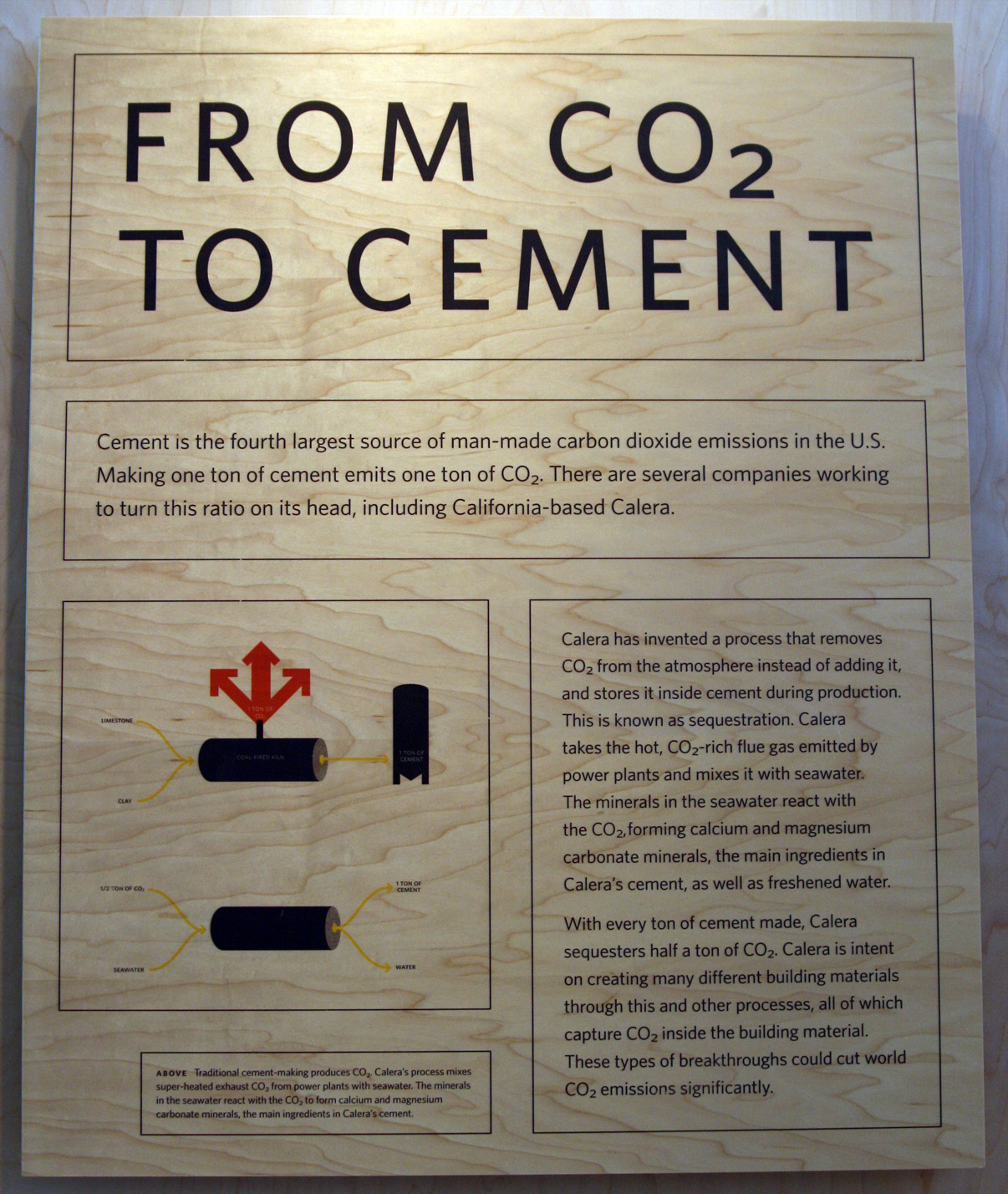