LCD Addon for Beagle.

Vijay Jalona

Koen Kooi
Op 5 mrt 2009, om 07:12 heeft Vijay Jalona het volgende geschreven:
> Hi All,
>
> I have been playing with beagle board for last couple of months, I
> have missed the ability to take it around and show it to the people
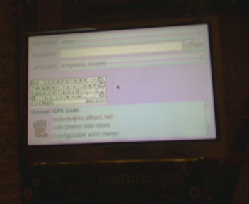
> as stand alone board as we have no LCD display. I put together a
> display board , attached pictures.
>
> I have Rev B6 so used DVI receiver, but now rev C supports LCD bus,
> this board can be easily configured to use LCD bus instead of DVI,
> Are there people who interested in this LCD panel, I was wondering
> if could sell it as an add on board to the beagle.
Nice! What pricepoint are you aiming for?
regards,
Koen

Nishanth Menon
>
>
> Nice! What pricepoint are you aiming for?
>
here goes:
* Resolutions: VGA, WVGA, etc..
* Touch screens: resistive (TSC2046 or TSC200x or the like controller)
or capacitive (dunno if this could be bought yet)..
* Backlight control.
* Maybe a few buttons (GPIO based)?
* ambient light sensor?
* oh, a mounted camera would be good.. ;)..
Regards,
NM
Vijay Jalona
Nishanth Menon
>
> I am curious to know about the application of ambient sensor.
>
based on the ambient light in the environment..I have it on my laptop
and it is kinda cool - no strain to the eye ;)
Regards,
Nishanth Menon

davidcb
waiting for Rev C.
I read in the Rev C thread that there was a possibility that PWM
signals would be added to the expansion connector for people using the
board for robotics.
David.
On Mar 5, 8:30 am, Vijay Jalona <vijayjal...@gmail.com> wrote:
> Hi NM, Koen,
>
> Thanks for the feedback. Here are the features.
>
> 1. Board is equipped with 640x480 VGA, LS037, currently I got FB driver
> working Linux 640x480
>
> 2. Touch support through TS2046
>
> 3. Back light control using I2C based PWM. Here again i really wish to use
> 3530 built in PWM but not comming out on expansion connector.
>
> 4. Few key are supported ( 4 arrows + 1 enter ) and 2 other keys keeping
> android in mind, but can be expanded if required. Used again I2C expandor
>
> Hmm as of now that's all, regarding Camera, I want to add but expansion
> connector limits it.
>
> NM,
>
> I am curious to know about the application of ambient sensor.
>
> Price really depends on volumes ;-), I need to work out.
>
> Regards,
> VJ
>

Frans Meulenbroeks
Frans
Sean D'Epagnier
Do you have schematics? I would like to see how you convert the DVI-D
to paralle.
I just finally got around to hooking at tfp401a up to convert DVI-D to
parallel.. but I am having issues.. it works for about 1 second, then
stops working for 6 seconds.. then repeats.
Sean

Gerald Coley
Vijay Jalona
Gerald Coley

Alessandro Corrêa Mendes
look? My adapter is a MODEL: USB-400.
Where is the indication of the device in Angstrom?
Alessandro
--
As informações contidas nesta mensagem são CONFIDENCIAIS, protegidas pelo sigilo legal e por direitos autorais. A divulgação, distribuição, reprodução ou qualquer forma de utilização do teor deste documento depende de autorização do emissor, sujeitando-se o infrator às sanções legais. Caso esta comunicação tenha sido recebida por engano, favor avisar imediatamente, respondendo esta mensagem.
Alessandro C. Mendes
Engº Eletrônico
PROBES - Soluções em Engenharia
Av. Shishima Hifumi 2911 - 12244-000
Parque Tecnológico - Sala 205
Urbanova - São José dos Campos - SP
Phone/FAX : +55-12-3947 1230
Gerald Coley
Sean D'Epagnier
> Hi Sean,
>
> May I know which product are you working? Looks like you have S/W issue
> rather than H/W, if the singal comes correct it will not be a issue with H/W
>
I believe so too. The signals all look correct on the scope, but the
hsync and vsync have the wrong polarity.
> I need to release schematics along with the board ( as it stokist will be
> selling the boards ), so full schematics will be open in short time.
>
> I am sending you only part of the schematics which converts the DVI to
> paralle. If you need any further help send your schematics I review.
>
I have a similar schematic:
http://digitalsurveyinstruments.com/beagleperiphials/hdmi2parallel/hdmi2parallel_schematic/hdmi2parallel.png
yours may be better mine was quick and dirty, and I think it works,
there are software problems though.
Sean

Preston Wilson
> The Rev C2 schematics are now on the web. http://beagleboard.org/hardware/design
would like to know the offset of the new lcd connectors on the board.
Thank you,
Preston
Gerald Coley
Preston Wilson
want. I apologize for not looking in the SRM before posting.
Preston
On Mar 19, 10:35 am, Gerald Coley <ger...@beagleboard.org> wrote:
> Gerbers will be posted when they are ready. Maybe tomorrow or maybe late
> next week. There is mechanical data for the LCD connector placement in the
> SRM.
>
> Gerald
>
Gerald Coley

Jason Kridner
Sean D'Epagnier
I finally got the psp display working (see screenshots) I have a
crappy camera it isn't blurry.
> I have Rev B6 so used DVI receiver, but now rev C supports LCD bus, this
> board can be easily configured to use LCD bus instead of DVI, Are there
> people who interested in this LCD panel, I was wondering if could sell it as
> an add on board to the beagle.
>
> I want your comments and suggestions
>
I noticed in your schematic you have OCK_INV pulled high. I tried it
both ways on mine, and the picture looks much better when OCK_INV is
low, maybe you can try soldering a switch on and flipping it to see
the difference?
Also a big problem I have is what to do with the DE line. If I
connect it to the tfp401a like you have in your schematic, the lcd
never turns on. If I connect it to vcc (3.3v) then the lcd turns on
and it works, but I have to connect it while the beagle is in uboot.
If I connect this pin after linux has booted, or just leave it
connected at startup Then the display is very light colored, and
hard to read. Has anyone seen this? Does anyone have hints?
Thanks,
Sean

linkr
I'm one of them who read this. Anyway, what is beagle board? Is it a
kind of dog surfing board for beagle?
D.Y.M
Vijay Jalona
Also a big problem I have is what to do with the DE line. If I
connect it to the tfp401a like you have in your schematic, the lcd
never turns on. If I connect it to vcc (3.3v) then the lcd turns on
and it works, but I have to connect it while the beagle is in uboot.
If I connect this pin after linux has booted, or just leave it
connected at startup Then the display is very light colored, and
hard to read. Has anyone seen this? Does anyone have hints?
Vijay Jalona
>> Thanks again. The mechanical information in the SRM is exactly what I
>> want. I apologize for not looking in the SRM before posting.
Any change in placement of J3 w.r.t B7, As I can not find offset of
mounting holes and J3 from right edge of the board in Table 28.
Regards,
VJ
Preston Wilson
which is exactly the offset to the center of J3 Pin 27 from the same
reference point on my rev B5 board.
-Preston
Preston Wilson
vertical offset (as pictured in Figure 53) is the same, but the
horizontal offset is not shown for the center of J3 Pin 27, and that
is what you are asking.
-Preston
Vijay Jalona
>
> Ugh, I didn't read your message close enough before replying. The
> vertical offset (as pictured in Figure 53) is the same, but the
> horizontal offset is not shown for the center of J3 Pin 27, and that
> is what you are asking.
>
> -Preston
Hm, Yes, I should have been more clear. I am asking what is horizontal
offset of J3 Pin 27
One more thing, J4, J5 neither pin numbers nor signals are in order,
If signals are routed for convenience ( to have minimum number of
layers ) why pin numbers in schematics are given in random order. Does
it fallow physical convention? Is it good to change the pin number in
correct physical order?
Regards,
VJ
Vijay Jalona
I am puzzled with the numbering convention of J4 and J5 headers. Does
it fallow physical convention of header? ( PINs in correct physical
order ). I hope that pins are numbered randomly just for convenience
and it fallow standard header convention physically. And it is correct
to import standard 1.27mm header in CAD? i.e
1-2
3-4
4-6
7-8
9-10
11-12
13-14
15-16
17-18
19-20
Regards,
VJ
Jason Kridner
> Hi All,
>
> I have been playing with beagle board for last couple of months, I have
> missed the ability to take it around and show it to the people as stand
> alone board as we have no LCD display. I put together a display board ,
> attached pictures.
>
> I have Rev B6 so used DVI receiver, but now rev C supports LCD bus, this
> board can be easily configured to use LCD bus instead of DVI, Are there
> people who interested in this LCD panel, I was wondering if could sell it as
> an add on board to the beagle.
>
> I want your comments and suggestions
>
> Vijay Jalona
Are the design materials available for this board? Is it possible for
people to buy the pre-assembled board or even just parts (like the
bare PCB)? In general, how do other people get one of these for
themselves?