Summary of my testing and debugging so far (part two: correction procedure, measured response) 1/29/13

Bob Katz
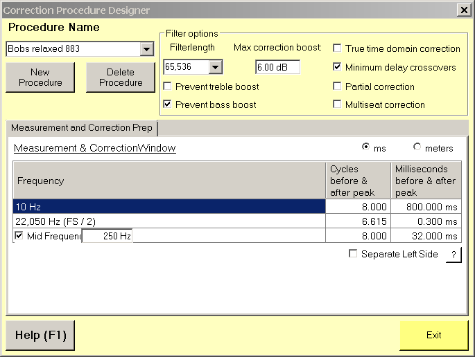
Attached is my "final" relaxed frequency domain correction procedure. What I mean by "relaxed" is it does not This worked for me at all sample rates as long as I tweaked the target appropriately as described in part 1. "Bobs 886 relaxed corr proc". This is 886 instead of 883 so that I would not get any measurement anomalies circa 20 khz. Basically it gives a slightly longer averaging of the high frequency section than recommended, but after all, it is only a few inches long :-).
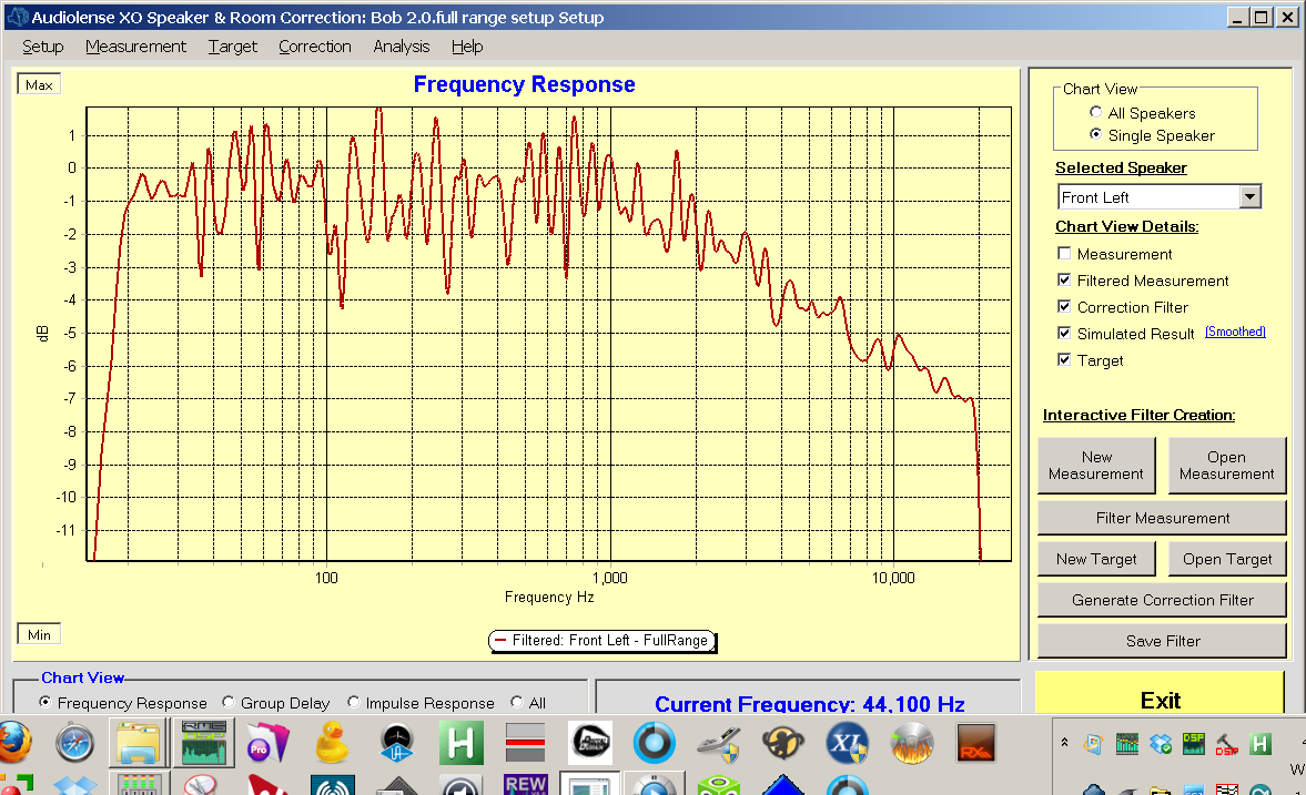
The next chart shows simulation and correction at 44.1 kHz. "Simulation & correction relaxed @ 441". Be aware this exposes the weakness of having a "relaxed" correction window which is also an analysis window because it does not show the true amplitude of the measurement response, it measures with too narrow a window for the most part. But by superimposing the correction curve it can expose if there are any supersonic or subsonic boosts which would be bad for the system or create too much attenuation. So the simulation line is not to be trusted. The overall attenuation came out to -20 dB, which is insignificant. In the end I ended up using 5 or a bit more dB of boost in JRiver or in VSTHost to get the SPL calibration I need in my system. I'll talk more about attenuation issues shortly.
The next chart shows simulation and correction at 96 kHz. "Simulation & correction relaxed @ 96". Don't jump, the scale is more zoomed, but the bass and mid frequency results are the same as at 44.1 k, I think. But you can see that we have to pay special attention to avoiding correction boost in the supersonic region by nudging the target down with selected points.
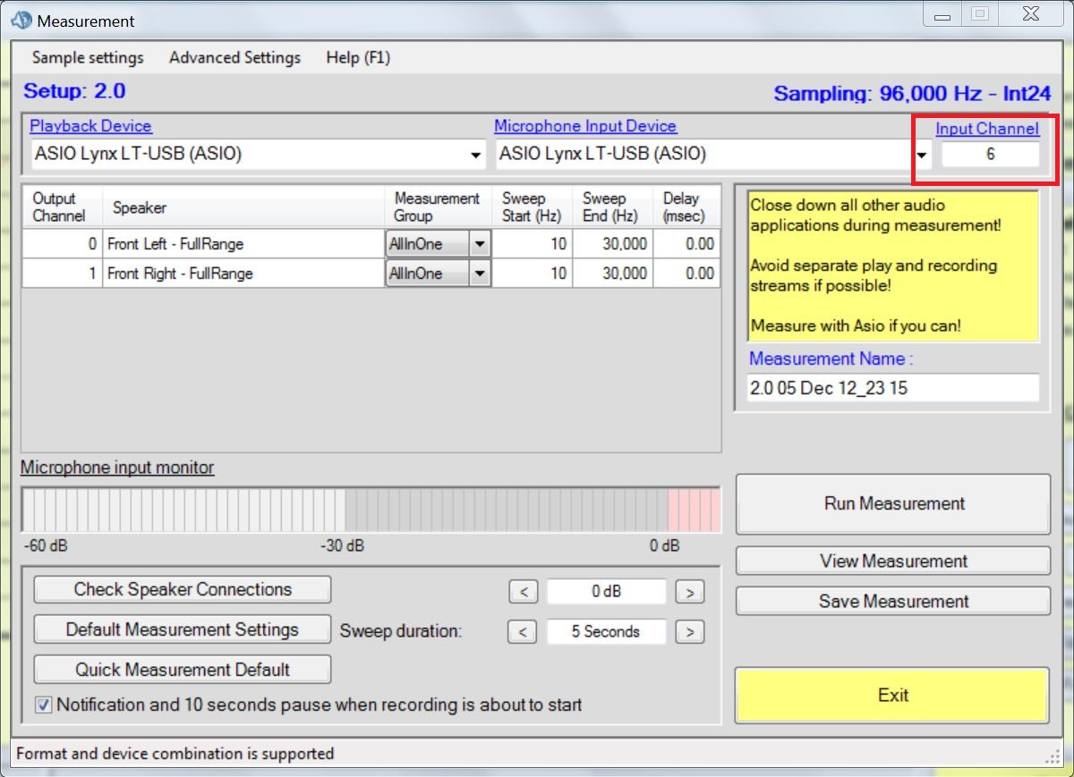
Now comes the pièce de résistance! The actual measured loopback from the combined, crossed over and corrected system loaded back into Audiolense. I had to use one interface to run a 6 channel convolver (for surround and two stereo subs) and another interface for Audiolense to run the mike and do the read and send the test tone. Both interfaces had to be locked together digitally to avoid issues.
First is the "Left ch. loopback freq response @ 44pt1". The supersonic spike is the result of an alias because at one point I ran my sweep to 24000 Hz which is a no-no as it is above the Nyquist Freq. It's "the little man who wasn't there". Bernt, I recommend that when the user changes his sample rate, you check that the maximum frequency of the sweep tone is Nyquist, maybe even set it for him.
This is the ACTUAL correct psychoacoustic effect of the relaxed frequency correctoin, and it conforms to my current criterion of "avoid overcorrection with no more than + or - 2 dB of excursion at any frequency" and I think it is the real deal. At least this week. We have not won the side bet with Bernt yet, not by a long shot. And I won't know the answer for several weeks until I play with correction a lot more. This measurement is such an amazing dream to see and when I saw it I sat stunned for several minutes. Because it took an hour or more to make the complicated patch, and because it proves the concept all the way through from the first measurement through the correction to the actual measurement of the corrected product. And the number of wiggles and their excursion is not so bad to my mind. A helluva lot more wiggles than I have been accustomed to see in simple analog systems, but hopefully not psychoacoustically too bad.
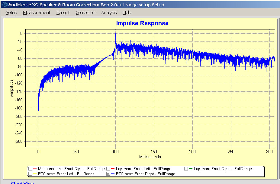
This next chart is the measured loopback impulse response, and it's pretty impressive, too. I don't know what the tiny little squiggles are but I think they are insignificant. I'm bowled over by the fact we can see the peak of the tweeter, then the midrange which is opposite polarity, then the midwoofer which is positive polarity again, and then the peak of the subwoofer, which appears to be positive also, all within 1 millisecond. This measurement is so right that it really shows the power of Audiolense, even with just "frequency domain correction".
I don't know the difference between the "log Impulse" and the ETC, so I'll show the ETC. "Right ch loopback log ETC @ 44pt1". Again, this is a microphone return of the convolved system! This is not a simulation. The left channel ETC is in that dreaded yellow color on a yellow background so I won't display it, but take it for granted it looks identical to this right channel. This measurement is the acoustician's "to die for" measurement, and it is the pièce de résistance of my room, and the main reason why this room has such good resolution of inner detail and allows me as a mastering engineer to make 0.25 dB EQ corrections and hear the difference. The basic criterion of a good ETC is that there should be no spikes in the room's early reflections greater than -15 dB for the first 20 or so milliseconds after the impulse. This room exceeds that by a large margin. NOtice how up to about 20 ms. there is no obvious reflection that exceeds -20 dB, then two little spikes at about -18 dB, followed by a gentle and continuous rolldown up to 200 ms. after the impulse and beyond (not shown).
I have to take a waterfall and Shroeder curve of this corrected impulse using REW to see what we've got. This is the response to die for, guys, it truly is.
Enjoy, please give your comments. Did I miss anything?
Best wishes,
Bob
Bob Katz 407-831-0233 DIGITAL DOMAIN | "There are two kinds of fools,
Recording, Mastering, Manufacturing  | One says-this is old and therefore good.
Author: Mastering Audio              | The other says-this is new and therefore
Digital Domain Website               | better."

No trees were killed in the sending of this message. However a large number
of electrons were terribly inconvenienced.
No more Plaxo, Linked-In, or any of the other time-suckers. Please contact me by regular email. Yes, we have a facebook page and a You-Tube site!

Bernt Ronningsbakk
Hi bob,


I’ve taken note of your request re the target tilting frequency, the spl
control after correction and the naming used in the config files. I
appreciate the input and I will look into it at the earliest convenience and
I expect to implement them. Can’t say when it will be out though. But it
will be out as soon as I’ve fixed a somewhat more demanding bug.
I also studied your charts with great interest.
IMO you did the right thing when you set the max boost back to 6dB. I suggested 18 dB when I did because with the measurement and target I had here it was needed to get you out of broad band dip territory. As it is now, 6dB seems just right. I have no plans to back out of the bet, though. The way I see it, there are two things to examine: One is more/less correction boost and the other is longer/shorter windows. We’ll get to that when we get to it.
About your loopback control measurement. There is a lot of ringing evident
in the impulse response. That is likely a product of the artifact peak just
past 20kHz that appears in the frequency domain. If you’ve got that under
control I think this is OK.
The bass boost and treble boost are partly in place to safeguard against
lazy target design. A careless user with lesser standards than yours can
draw a fairly straight target that doesn’t account for the band width of the
speakers and still get most of the benefits.


For the sophisticated user the treble boost comes in handy for those who
wants to correct the speaker through the low pass function of the DAC. As
the frequency response drops steeply it is very difficult to draw the target
with enough precision to avoid unintended attenuation or amplification. And
keeping the treble boost checked will avoid creating a filter that amplifies
the treble by some 10-30 dB way down in the passband, steels digital
headroom and sends a very strong signal to the tweeter that will mostly only
produce heat and distortion.


For the sophisticated user with an unconventional bass solution that has
good sensitivity and ample SPL capacity at very low frequencies but still a
response that rises rapidly towards 100 Hz, unchecking the bass boost will
enable him to boost the bass without any limits. There are unlikely to be
any narrow band dips deep down that can be overcorrected, so this is likely
to work well in practice – at least it has the few times I’ve encountered
it.
The ETC view. At first I suspected that the time domain synchronization
between recording and playback was off when you did the control measurement.
Something starts to rise above the noise floor around 30 ms before the main
peak, but minimumdelay filtes doesn’t do anything until around  minus 10 ms.
Give or take. The rise could be an artifact produced by the ETC method. I
prefer to use the log impulse response view. It shows everything I can read
out of an ETC and it doesn’t water down sudden rises and falls in the
impulse response. If you see something similar with the log view there is
likely to be a timing problem in your loopback measurement.
Kind regards,
Bernt
--
--
Audiolense User Forum.
http://groups.google.com/group/audiolense?hl=en?hl=en
To post to this group, send email to audio...@googlegroups.com
To unsubscribe, send email to audiolense+...@googlegroups.com
---
You received this message because you are subscribed to the Google Groups "Audiolense User Forum" group.
To unsubscribe from this group and stop receiving emails from it, send an email to audiolense+...@googlegroups.com.
For more options, visit https://groups.google.com/groups/opt_out.

Brad
Looking good Bob. Gotta love that reflection free zone you have.
Bob Katz
Hi bob, I’ve taken note of your request re the target tilting frequency, the spl control after correction and the naming used in the config files. I appreciate the input and I will look into it at the earliest convenience and I expect to implement them. Can’t say when it will be out though. But it will be out as soon as I’ve fixed a somewhat more demanding bug.
BTW, last night I decided to experiment on a different hinge point since I got it in my mind that maybe the subjective 2 kHz response was a little bit depressed. My system sounds so sweet now with the majority of my reference recordings that I fear I may engineer too much presence into the products I produce for my clients. But there are still recordings that I know are too extreme in the high end that are very hard to listen to, so I feel we're on the right track.
So as an experiment I moved the hinge point to 1.5 kHz, and in an hour or two I achieved three targets (for 44.1, 48, and 88+ ks/s) that had a perfect straight line (by inspection and zooming in the main window) from the new hinge point to a fixed point at 20 kHz, and which matched at 2 kHz, 10 kHz, and 20 kHz to less than 0.1 dB for all three targets, I then generated filters and listened. In five minutes I rejected the 1.5 kHz hinge point! It was too bright. So a 1 kHz hinge point is probably "just about right". I might experiment (in my copious free time?) with 1.1 kHz and see how it sounds, but then again, let sleeping dogs lie----the vast majority of my recording collection sounds wonderful with the 1 kHz hinge point and 20 kHz down "officially" 6 dB in the target designer. It's not down 6 dB in the main window result but we'll leave that for another discussion.
The need for me to put in placeholders in the target designer at some intermediate points, including 17 kHz, in order to achieve a visual straight (diagonal) line in the 88 ks/s target worries me. It means that this target could sound different from the 44 and 48 targets just because it is designed differently. That's because the extended response out to 40 kHz and the need to put additional points in the target design above 20 kHz affect the interpolated curve created by the target designer in the below 20 kHz range. This cannot be seen in the lower-resolution target window and have to be examined with a fine zoom in the main window after correction has been done and viewing the target line.
My usual philosophy with the group of reference recordings I know well, is to engineer the high end of my system so about 20% of them are a little bit too bright and then I'm on the right track. Right now it sounds like 90% of them sound really nice. I'm talking about the 1 to 5 kHz range, by the way, I think the 5 to 20 kHz range is working very well and so I think my choice of anchor point at 20 kHz is working well. That's why I have to try the 1.1 kHz hinge point to see, because if I was just an audiophile listener I would be so thrilled with my system with the 1 kHz hinge point I would jump up and down with glee and just stop working and listen!
Guys who are reading this, keep in mind that this hinge point and high frequency down choice are probably only correct for the frequency domain correction procedure, not for the TTD. In my experience with preringing effects, they soften the apparent transient response of a system and people tend to try to make up for it with high frequency boosts. But my philosophy says that is wrong and that preringing is the cause and until it is fixed then no amount of high frequency correction can produce a system that really sounds "good". It can sound "mellifluous" but never right, to my mind.
About your loopback control measurement. There is a lot of ringing evident in the impulse response. That is likely a product of the artifact peak just past 20kHz that appears in the frequency domain. If you’ve got that under control I think this is OK.
The bass boost and treble boost are partly in place to safeguard against lazy target design. A careless user with lesser standards than yours can draw a fairly straight target that doesn’t account for the band width of the speakers and still get most of the benefits. For the sophisticated user the treble boost comes in handy for those who wants to correct the speaker through the low pass function of the DAC. As the frequency response drops steeply it is very difficult to draw the target with enough precision to avoid unintended attenuation or amplification. And keeping the treble boost checked will avoid creating a filter that amplifies the treble by some 10-30 dB way down in the passband, steels digital headroom and sends a very strong signal to the tweeter that will mostly only produce heat and distortion. For the sophisticated user with an unconventional bass solution that has good sensitivity and ample SPL capacity at very low frequencies but still a response that rises rapidly towards 100 Hz, unchecking the bass boost will enable him to boost the bass without any limits. There are unlikely to be any narrow band dips deep down that can be overcorrected, so this is likely to work well in practice – at least it has the few times I’ve encountered it.
The ETC view. At first I suspected that the time domain synchronization between recording and playback was off when you did the control measurement. Something starts to rise above the noise floor around 30 ms before the main peak, but minimumdelay filtes doesn’t do anything until around minus 10 ms. Give or take. The rise could be an artifact produced by the ETC method. I prefer to use the log impulse response view. It shows everything I can read out of an ETC and it doesn’t water down sudden rises and falls in the impulse response. If you see something similar with the log view there is likely to be a timing problem in your loopback measurement.
Thanks very much,
Bob Katz
The ETC view. At first I suspected that the time domain synchronization
between recording and playback was off when you did the control measurement.
Something starts to rise above the noise floor around 30 ms before the main
peak, but minimumdelay filtes doesn't do anything until around minus 10 ms.
Give or take. The rise could be an artifact produced by the ETC method. I
prefer to use the log impulse response view. It shows everything I can read
out of an ETC and it doesn't water down sudden rises and falls in the
impulse response. If you see something similar with the log view there is
likely to be a timing problem in your loopback measurement.
Can we all agree on the term "loopback" to mean a measurement of the fully convolved system taken with a microphone, not a simulation?
Lastly, in the frequency response window, the loopback method allows me to use a smoothing for measurement that is the default window rather than the relaxed window used. I hope Bernt will also add a separate correction and analysis window for the frequency domain correction so the analysis will be more correct with simulation.
As for the ringing in the loopback, I count 11 cycles in 0.5 ms before the impulse, corresponding with 22 kHz. There we go! That could cause the subtle HF distortion I'm hearing.
And about 13 cycles in 0.5 ms. after the impulse, corresponding with 26 kHz, which is impossible with 44.1k sampling so it's just a bad estimate :-).
Next thing I'll do is take a loopback at 96 ks/s for more precise analysis. I pray the ringing is not really there and it is an aliasing artifact.
Best wishes,
Bernt Ronningsbakk
Hi Bob,
There is no question that the HF spike makes a huge influence of what we see here. I’ve never seen aliasing artifacts such as this appear in these measurements before so I am really puzzled by this. Since we’ve seen that your correction filters don’t have a big spike just past 20kHz this must be caused by something else.
I am not sure I understand what you’re asking for with the separate windows. The smoothed measurement and the smoothed simulation are treated exactly the same. I’ve attached a control measurement I did several years ago. Pink curve is the simulated response. The blue curve on the top is the control measurement. The artifacts around 10Hz are post processing artifacts, so you can ignore that. Look how close the simulation and the control measurement is. If your loopback and convolution works 100% I fully expect your system to be even closer to the simulation than this one. But only if you use the same correction procedure to smooth the control measurement. And if you do it this way, and they don’t have the similarities you see here, there is something bad happening somewhere in your loop.
Kind regards,
Bernt
From: audio...@googlegroups.com [mailto:audio...@googlegroups.com] On Behalf Of Bob Katz
Sent: Wednesday, January 30, 2013 12:37 PM
To: audio...@googlegroups.com
--

Alan Jordan
Bernt Ronningsbakk
About a level matching feature.
How do you want it to work? How would you do it if you were to do it manually? I need programmable details on how to determine what the current level is.
About the target smoothing. The resulting target will cut corners, but it will always touch the straight line between two points. If you want to create a straight line, put two targets on that line next to each other, on each end.
Kind regards,
Bernt
--
Bob Katz
As for the separate analysis and control windows, you have this functionality in the TTD, so why not in the frequency domain function?
You wrote:
On 1/30/13 7:59 AM, Bernt Ronningsbakk wrote:
Hi Bob,


There is no question that the HF spike makes a huge influence  of what we
see here. I've never seen aliasing artifacts such as this appear in these
measurements before so I am really puzzled by this. Since we've seen that
your correction filters don't have a big spike just past 20kHz this must be
caused by something else.


I am not sure I understand what  you're asking for with the separate
windows. The smoothed measurement and the smoothed simulation are treated
exactly the same.  I've attached a control measurement I did several years
ago. Pink curve is the simulated response.  The blue curve on the top is the
control measurement. The artifacts around 10Hz are post processing
artifacts, so you can ignore that. Look how close the simulation and the
control measurement is. If your loopback and convolution works 100% I fully
expect your system to be even closer to the simulation than this one. But
only if you use the same correction procedure to smooth the control
measurement. And if you do it this way, and they don't have the similarities
you see here, there is something bad happening somewhere in your loop.
BK
Bob Katz
Please try both a relaxed correction a la Bob and the default frequency correction a la Bernt and report here whether you hear more or less purity of tone, veiling or harshness with one setup or the other but with identical target. After all, I have a case of Norwegian Ringnes beer on the line on this bet. :-)
I have also been through Fuzzmeasure (on the Mac) and it is quite useful and ergonomic, but awkward because when you want to change the window for each successive measurement, you have to jump through hoops, and his default window is rectangular, which is wrong, wrong, wrong. (I learned that the hard way). And then it is not possible to make a curved window in FuzzMeasure which is symmetrical about the impulse. He does not allow negative time in front of the impulse. So I had to abandon Fuzzmeasure. Chris Luscio, the developer, like Bernt, is a one-man shop, and (unlike Bernt) doesn't put all his time into his product.
I also have Spectrafoo, and it is the most effective high resolution distortion analyzer I own and I use it for that all the time, but for room response measurements it's not been updated in a long time and doesn't have the latest desirable features. BJ, the developer, is a genius, but he does not have the best ability to design and direct ergonomic software, and so you really have to be an expert to get the most out of Spectrafoo. Don't get me wrong, BJ and his team will help you all the way, but like with Bernt, you have to get hand-holding. That's why we want to help Bernt to get an FAQ and a true manual out of this. Audiolense is too precious to us!
REW is the best candidate for outside loopback that I've found, but it only works at 44.1 and 48 kHz. But it is useful as a cross check to Audiolense, provided that you can set the same window, and there is no variable window function (yet) in REW so you can only examine a decade or so at a time and try to estimate what window Audiolense is working with at that time!
So, assuming we can trust Audiolense (which I do, mostly), doing a loopback with it would be the best thing. And since there is a one-computer license, you have to perform the loopback in the same computer with two different interfaces. I do not trust any of the windows sound drivers for this, maybe because I'm old-fashioned. The only thing I trust is ASIO, it has the resolution and the bit-transparency to do it right. Which means you have to have TWO ASIO soundcards in your computer (or one connected via USB and one PCI, or maybe even two USB if your computer is fast enough). And don't trust any old soundcard, use a reputable brand like Lynx or RME or possibly Motu, or even better, Prism.
Attached is my block diagram of what I have to go through for loopback... I have a programmable digital router to remember the digital routes. Also, both my interfaces are AES/EBU in and out so I have to use an external ADC and mike preamp and lock one of the interfaces to its sync. The RME is the master ASIO interface, connected to Audiolense for analysis and generation. The second interface runs the convolution in "live" mode and is locked digitally to the first one via AES/EBU. Since JRiver does not allow live in using the same interface (yet), then you have to construct a convolver using VSTHost (a great program--donate to the developer if you use it) and ConvolverVST (from SourceForge). Take your time with both of those. It took me days and days to get VSTHost to do what I want to do and learn the quirks of ConvolverVST. There is one version of ConvolverVST that will not install, but there is a version whose installer does work. Read the documentation on both, the full manuals, these are products that actually have manuals!
REMEMBER TO USE YOUR ANALOG DOMAIN VOLUME CONTROL, MUTE AND DIM BUTTONS TO PROTECT YOURSELF. TURN IT DOWN AT EACH STEP IN THE PROCESS AND CONFIRM THAT THINGS ARE WORKING BEFORE PROCEEDING. IF YOU MAKE A WRONG PATCH YOU COULD BLOW YOUR TWEETERS! (OR MORE).
If you're not intimidated by now, then you should be. Every time I set up a loopback I even intimidate myself!
Description of diagram:
Step 1) Measure (at the bottom of the diagram)
From left to right:
Mike is in ADC goes into
RME Madi locked to wordclock from ADC. Audiolense is using the RME in 5.1 setup mode (for crossover to subs and surround speakers if used, so there are six outputs in my system)
into
6 channel DAC and then the loudspeakers
Requires a different digital routing preset in the router! Lynx interface is not involved in this step.
Step 2) (not shown) Listen to music through the convolver. Connect VST Host to Lynx interface with stereo in and 6 channel (or 4 channel or whatever) out. Send CD player or other stereo digital source into Lynx interface and lock Lynx to CD player. Connect VSTHost running ConvolverVST and Voxengo Elephant (for 24-bit dither) to 6 channel DAC and then the loudspeakers. Requires a different digital routing preset in the router! RME interface is NOT INVOLVED in this listening step.
Step 3) Measure Loopback (at top of diagram). Both interfaces are involved in this step.
Mike is in ADC goes into
RME Madi locked to wordclock from ADC. Audiolense is using the RME in 2.0 setup mode as this is now to be treated as complete full range stereo system, so only 2 outputs are used.
into
Lynx is locked to this digital source in stereo
VSTHost is connected to Lynx sending 6 channel (or 4 channel or whatever) to the DAC and the loudspeakers.
That's it! Good luck, it took me days and days and days to get this setup perfected.
Bob
On 1/30/13 8:10 AM, Alan Jordan wrote:
Hi Bob,

Thank you for posting your targets.
Bob Katz
About a level matching feature.


How do you want it to work? How would you do it if you were to do it
manually? I need programmable details on how to determine what the current
level is.
After I do a second correction at a different sample rate or with a different target shape, due to slightly different positions of the target points or who knows what, the attenuation is different usually, by a small amount.
a) Perhaps simply a button in the main window to nudge the target up or down in 0.1 dB increments? Or a setting to set the 1 kHz attenuation level to a certain point.
I would say that if your first correction, the target lands at -17.6 dB (1 kHz point), make it easy for us to set it to an easy number to remember, like -18.0 dB for this and all subsequent corrections. As long as it's consistent from correction to correction, in the playback software (the convolver, e.g. JRiver) we can add a fixed attenuation or boost if we need for SPL calibration and of course it's up to us to make sure it's not clipping. But even more useful would be if you provide a warning in your software if we attempt to raise the target rather than lower it, that "it's at your own risk as it might cause clipping of your DAC". You could have a button that says, "I know, I'll take the risk" and that then gives us the power to raise the target.
How's that?
Bob
Subject: Re: [audiolense] Summary of my testing and debugging so far (part
two: correction procedure, measured response) 1/29/13


Hi, Bernt.

On 1/29/13 8:01 PM, Bernt Ronningsbakk wrote:

Hi bob,


I've taken note of your request re the target tilting frequency, the spl
control after correction and the naming used in the config files. I
appreciate the input and I will look into it at the earliest convenience and
I expect to implement them. Can't say when it will be out though. But it
will be out as soon as I've fixed a somewhat more demanding bug.


I know how hard it is to do this, and you have accomplished so much
yourself. In most cases these kinds of programs for niche markets end up
with far less power and flexibility that you have already done. But if you
want Audiolense to move into the professional market, where speed, power and
repeatability exist, we have to make these things work and as ergonomically
as possible. I do think that Audiolense is truly the first
"audiophile-quality" room correction system I have ever encountered, but for
ergonomic reasons I could not recommend Audiolense in its current state to a
professional wanting to correct a room in a practical and short time. Most
people do not have the patience that I have to turn a concave line into a
straight line in a practical target. When I used to do a lot of biasing and
setting my analog tape recorders, at the age of 23 years I had the
"inspiration" that I should adjust the 10 kHz response to +0.1 dB to
compensate for losses in the analog tape over time and generation losses
when copying. I quickly abandoned that as I immediately discovered that even
0.1 dB at 10 kHz emphasizes sibilance in an unnatural way. So I returned to
"as flat as possible" for the rest of my career. Fast forward to 2013 and we
have the same issue, since with DRC, "tilted" means "flat", we have to have
a mechanism that precisely hinges the high frequency part of the target with
a fixed point in the midrange once the user has achieved a perfectly
straight (diagonal) line above the hinge point.

BTW, last night I decided to experiment on a different hinge point since I
got it in my mind that maybe the subjective 2 kHz response was a little bit
depressed. My system sounds so sweet now with the majority of my reference
recordings that I fear I may engineer too much presence into the products I
produce for my clients. But there are still recordings that I know are too
extreme in the high end that are very hard to listen to, so I feel we're on
the right track.

So as an experiment I moved the hinge point to 1.5 kHz, and in an hour or
two I achieved three targets (for 44.1, 48, and 88+ ks/s) that had a perfect
straight line (by inspection and zooming in the main window) from the new
hinge point to a fixed point at 20 kHz, and which matched at 2 kHz, 10 kHz,
and 20 kHz to less than 0.1 dB for all three targets, I then generated
filters and listened. In five minutes I rejected the 1.5 kHz hinge point! It
was too bright. So a 1 kHz hinge point is probably "just about right". I
might experiment (in my copious free time?) with 1.1 kHz and see how it
sounds, but then again, let sleeping dogs lie----the vast majority of my
recording collection sounds wonderful with the 1 kHz hinge point and 20 kHz
down "officially" 6 dB in the target designer. It's not down 6 dB in the
main window result but we'll leave that for another discussion.

The need for me to put in placeholders in the target designer at some
intermediate points, including 17 kHz, in order to achieve a visual straight
(diagonal) line in the 88 ks/s target worries me. It means that this target
could sound different from the 44 and 48 targets just because it is designed
differently. That's because the extended response out to 40 kHz and the need
to put additional points in the target design above 20 kHz affect the
interpolated curve created by the target designer in the below 20 kHz range.
This cannot be seen in the lower-resolution target window and have to be
examined with a fine zoom in the main window after correction has been done
and viewing the target line.

My usual philosophy with the group of reference recordings I know well, is
to engineer the high end of my system so about 20% of them are a little bit
too bright and then I'm on the right track. Right now it sounds like 90% of
them sound really nice. I'm talking about the 1 to 5 kHz range, by the way,
I think the 5 to 20 kHz range is working very well and so I think my choice
of anchor point at 20 kHz is working well. That's why I have to try the 1.1
kHz hinge point to see, because if I was just an audiophile listener I would
be so thrilled with my system with the 1 kHz hinge point I would jump up and
down with glee and just stop working and listen!

Guys who are reading this, keep in mind that this hinge point and high
frequency down choice are probably only correct for the frequency domain
correction procedure, not for the TTD. In my experience with preringing
effects, they soften the apparent transient response of a system and people
tend to try to make up for it with high frequency boosts. But my philosophy
says that is wrong and that preringing is the cause and until it is fixed
then no amount of high frequency correction can produce a system that really
sounds "good". It can sound "mellifluous" but never right, to my mind.


About your loopback control measurement. There is a lot of ringing evident
in the impulse response. That is likely a product of the artifact peak just
past 20kHz that appears in the frequency domain. If you've got that under
control I think this is OK.


I'm not sure what that artifact peak is in the loopback. I said it might be
due to aliasing but this ringing that we see is not inconsequential as I
claimed. It could be due to artifacts of the convolver or something which I
do not know. The ringing that you see could easily be affecting the
distortion of the system and there is still some subtle residual harshness
at high frequencies when things get very loud in the high frequency range
playing music that makes this system sound "just a little bit digital"
compared to my analog correction system. Not enough right now for me to want
to change back, but I do want to get to the bottom of it soon. The loopback
test is very instructive and a very high resolution proof of concept.
Unfortunately it takes so much work to set up and patch the system for a
complete loopback that the work is very hard to handle. One mispatch and it
could cause tweeter-blowing feedback, I am sure of it. So there is more work
to do!


The bass boost and treble boost are partly in place to safeguard against
lazy target design. A careless user with lesser standards than yours can
draw a fairly straight target that doesn't account for the band width of the
speakers and still get most of the benefits.


For the sophisticated user the treble boost comes in handy for those who
wants to correct the speaker through the low pass function of the DAC. As
the frequency response drops steeply it is very difficult to draw the target
with enough precision to avoid unintended attenuation or amplification. And
keeping the treble boost checked will avoid creating a filter that amplifies
the treble by some 10-30 dB way down in the passband, steels digital
headroom and sends a very strong signal to the tweeter that will mostly only
produce heat and distortion.


For the sophisticated user with an unconventional bass solution that has
good sensitivity and ample SPL capacity at very low frequencies but still a
response that rises rapidly towards 100 Hz, unchecking the bass boost will
enable him to boost the bass without any limits. There are unlikely to be
any narrow band dips deep down that can be overcorrected, so this is likely
to work well in practice - at least it has the few times I've encountered
it.


Thanks for that information. So much to learn!


The ETC view. At first I suspected that the time domain synchronization
between recording and playback was off when you did the control measurement.
Something starts to rise above the noise floor around 30 ms before the main
peak, but minimumdelay filtes doesn't do anything until around  minus 10 ms.
Give or take. The rise could be an artifact produced by the ETC method. I
prefer to use the log impulse response view. It shows everything I can read
out of an ETC and it doesn't water down sudden rises and falls in the
impulse response. If you see something similar with the log view there is
likely to be a timing problem in your loopback measurement.


I'll stick with log impulse view, then. Now we have to conquer the ringing
in the impulse response of the loopback, try to isolate its cause. It could
easily be the cause of the last bit of perceived harshness that I still hear
in this system and which probably would bother only a few well-trained
engineers like myself with a room and system as well-behaved as mine.


Thanks very much,


Bob
Bernt Ronningsbakk
Bob,


I agree about the ringing issue.


There is no need for a separate window with a frequency correction.
Kind regards,
Bernt
From: audio...@googlegroups.com [mailto:audio...@googlegroups.com] On Behalf Of Bob Katz
Sent: Wednesday, January 30, 2013 4:13 PM
To: audio...@googlegroups.com
--
Bob Katz
Bob, I agree about the ringing issue. There is no need for a separate window with a frequency correction.
Best wishes,
Bob

Mitch Global
--
Bob Katz
I do have to get to the bottom of the ringing! The RTL utility should not be needed. Latency is not an issue. After all, Audiolense can deal with many milliseconds of "latency" when it makes its measurement, so, linking two soundcards together with that additional latency should not faze audiolense, as long as they are locked together to the sample (and again, I GUARANTEE THAT THEY ARE, with NO DRIFT). All you get by chaining two interfaces with their software is just one large addition of an EXACT multiple of one sample time delay at the sample rate in question.
Best wishes,
Bob
 Hi, Alan! You are clearly the true combination of audiophile and audio
engineer!  Now you can try frequency correction with a useful target. My
Revel speakers might have a touch of that BBC 2 kHz dip, too, but now with
Audiolense and a straight diagonal down from 1 kHz, I think the curve is
taken care of naturally. Try sliding your hinge point up 0.1 kHz at a time
and report here. For me the height of the 20 kHz point determines the
"cymbals" and the choice of hinge point (1 kHz or higher) point determines
the upper mid frequency "presence".

Please try both a relaxed correction a la Bob and the default frequency
correction a la Bernt and report here whether you hear more or less purity
of tone, veiling or harshness with one setup or the other but with
identical target. After all, I have a case of Norwegian Ringnes beer on the
line on this bet. :-)

I have also been through Fuzzmeasure (on the Mac) and it is quite useful
and ergonomic, but awkward because when you want to change the window for
each successive measurement, you have to jump through hoops, and his
default window is rectangular, which is wrong, wrong, wrong. (I learned
that the hard way). And then it is not possible to make a curved window in
FuzzMeasure which is symmetrical about the impulse. He does not allow
negative time in front of the impulse. So I had to abandon Fuzzmeasure.
Chris Luscio, the developer, like Bernt, is a one-man shop, and (unlike
Bernt) doesn't put all his time into his product.

I also have Spectrafoo, and it is the most effective high resolution
distortion analyzer I own and I use it for that all the time, but for room
response measurements it's not been updated in a long time and doesn't have
the latest desirable features. BJ, the developer, is a genius, but he does
not have the best ability to design and direct ergonomic software, and so
you really have to be an expert to get the most out of Spectrafoo. Don't
get me wrong, BJ and his team will help you all the way, but like with
Bernt, you have to get hand-holding. That's why we want to help Bernt to
get an FAQ and a true manual out of this. Audiolense is too precious to us!

REW is the best candidate for outside loopback that I've found, but it
only works at 44.1 and 48 kHz. But it is useful as a cross check to
Audiolense, provided that you can set the same window, and there is no
variable window function (yet) in REW so you can only examine a decade or
so at a time and try to estimate what window Audiolense is working with at
that time!

So, assuming we can trust Audiolense (which I do, mostly), doing a
loopback with it would be the best thing. And since there is a one-computer
license, you have to perform the loopback in the same computer with two
different interfaces. I do not trust any of the windows sound drivers for
this, maybe because I'm old-fashioned. The only thing I trust is ASIO, it
has the resolution and the bit-transparency to do it right. Which means you
have to have TWO ASIO soundcards in your computer (or one connected via USB
and one PCI, or maybe even two USB if your computer is fast enough). And
don't trust any old soundcard, use a reputable brand like Lynx or RME or
possibly Motu, or even better, Prism.

Attached is my block diagram of what I have to go through for loopback...
I have a programmable digital router to remember the digital routes. Also,
both my interfaces are AES/EBU in and out so I have to use an external ADC
and mike preamp and lock one of the interfaces to its sync. The RME is the
master ASIO interface, connected to Audiolense for analysis and generation.
The second interface runs the convolution in "live" mode and is locked
digitally to the first one via AES/EBU. Since JRiver does not allow live in
using the same interface (yet), then you have to construct a convolver
using VSTHost (a great program--donate to the developer if you use it) and
ConvolverVST (from SourceForge). Take your time with both of those. It took
me days and days to get VSTHost to do what I want to do and learn the
quirks of ConvolverVST. There is one version of ConvolverVST that will not
install, but there is a version whose installer does work. Read the
documentation on both, the full manuals, these are products that actually
have manuals!

REMEMBER TO USE YOUR ANALOG DOMAIN VOLUME CONTROL, MUTE AND DIM BUTTONS TO
PROTECT YOURSELF. TURN IT DOWN AT EACH STEP IN THE PROCESS AND CONFIRM THAT
THINGS ARE WORKING BEFORE PROCEEDING. IF YOU MAKE A WRONG PATCH YOU COULD
BLOW YOUR TWEETERS! (OR MORE).

If you're not intimidated by now, then you should be. Every time I set up
a loopback I even intimidate myself!


Description of diagram:

Step 1) Measure (at the bottom of the diagram)

From left to right:

Mike is in ADC goes into

RME Madi locked to wordclock from ADC. Audiolense is using the RME in 5.1
setup mode (for crossover to subs and surround speakers if used, so there
are six outputs in my system)

into

6 channel DAC and then the loudspeakers

Requires a different digital routing preset in the router!  Lynx interface
is not involved in this step.


Step 2) (not shown) Listen to music through the convolver. Connect VST
Host to Lynx interface with stereo in and 6 channel (or 4 channel or
whatever) out. Send CD player or other stereo digital source into Lynx
interface and lock Lynx to CD player. Connect VSTHost running ConvolverVST
and Voxengo Elephant (for 24-bit dither) to 6 channel DAC and then the
loudspeakers.  Requires a different digital routing preset in the router!
RME interface is NOT INVOLVED in this listening step.


Step 3) Measure Loopback (at top of diagram).  Both interfaces are
involved in this step.

Mike is in ADC goes into

RME Madi locked to wordclock from ADC. Audiolense is using the RME in 2.0
setup mode as this is now to be treated as complete full range stereo
system, so only 2 outputs are used.

into

Lynx is locked to this digital source in stereo

VSTHost is connected to Lynx sending 6 channel (or 4 channel or whatever)
to the DAC and the loudspeakers.


That's it! Good luck, it took me days and days and days to get this setup
perfected.


Bob


On 1/30/13 8:10 AM, Alan Jordan wrote:

Hi Bob,

Thank you for posting your targets.


snip


--

Bob Katz 407-831-0233 DIGITAL DOMAIN | "There are two kinds of fools,
Recording, Mastering, Manufacturing  | One says-this is old and therefore good.
Author: *Mastering Audio              *| The other says-this is new and thereforeDigital Domain Website <http://www.digido.com/>               | better."

No trees were killed in the sending of this message. However a large number
of electrons were terribly inconvenienced.*No more Plaxo, Linked-In, or any of the other time-suckers. Please contact me by regular email. Yes, we have a facebook page and a You-Tube site!*

     --
--
Audiolense User Forum.
http://groups.google.com/group/audiolense?hl=en?hl=en
To post to this group, send email to audio...@googlegroups.com
To unsubscribe, send email to audiolense+...@googlegroups.com

---
You received this message because you are subscribed to the Google Groups
"Audiolense User Forum" group.
To unsubscribe from this group and stop receiving emails from it, send an
email to audiolense+...@googlegroups.com.
For more options, visit https://groups.google.com/groups/opt_out.

Walter_TheLion

Jarle Bergene
--
Bob Katz
We're talking about the correction procedure designer. Set it for TTD in the popup window and you'll see there is an analysis window and a separate TTD correction "subwindow". Bernt is trying to tell us there is no need for two windows so that is my confusion as well. We're all learning a little bit at a time.
This correction window provides the smoothing parameters for the filtering when you are in the main screen and you choose filtering. It governs the amount of filtering and if you change it, will make the amplitude excursions in the filtered frequency response look different! It makes you think the frequency response of your speakers is changing. Bernt knows how the program works, but my assumption is the analysis filtering setting kicks in when you do the initial filtering, and the correction filtering on top of the analysis filtering kicks in when you do the correction and view the simulation.
Does this help?
Bob
 DIGITAL DOMAIN | "There are two kinds of fools,
Recording, Mastering, Manufacturing  | One says-this is old and therefore good.
Author: *Mastering Audio              *| The other says-this is new and thereforeDigital Domain Website <http://www.digido.com/>               | better."

No trees were killed in the sending of this message. However a large number
of electrons were terribly inconvenienced.*No more Plaxo, Linked-In, or any of the other time-suckers. Please contact me by regular email. Yes, we have a facebook page and a You-Tube site!*

     --
--
Audiolense User Forum.
http://groups.google.com/group/audiolense?hl=en?hl=en
To post to this group, send email to audio...@googlegroups.com
To unsubscribe, send email to audiolense+...@googlegroups.com

---
You received this message because you are subscribed to the Google Groups
"Audiolense User Forum" group.
To unsubscribe from this group and stop receiving emails from it, send an
email to audiolense+...@googlegroups.com.
For more options, visit https://groups.google.com/groups/opt_out.
Bernt Ronningsbakk
Thank you Bob,
I think I’ve got the input I need now.
--
Mitch Global
Alan Jordan
Bob Katz
Bob
 wrote:


  Hi, Alan! You are clearly the true combination of audiophile and audio
engineer!  Now you can try frequency correction with a useful target. My
Revel speakers might have a touch of that BBC 2 kHz dip, too, but now with
Audiolense and a straight diagonal down from 1 kHz, I think the curve is
taken care of naturally. Try sliding your hinge point up 0.1 kHz at a time
and report here. For me the height of the 20 kHz point determines the
"cymbals" and the choice of hinge point (1 kHz or higher) point determines
the upper mid frequency "presence".

Please try both a relaxed correction a la Bob and the default frequency
correction a la Bernt and report here whether you hear more or less purity
of tone, veiling or harshness with one setup or the other but with
identical target. After all, I have a case of Norwegian Ringnes beer on the
line on this bet. :-)

I have also been through Fuzzmeasure (on the Mac) and it is quite useful
and ergonomic, but awkward because when you want to change the window for
each successive measurement, you have to jump through hoops, and his
default window is rectangular, which is wrong, wrong, wrong. (I learned
that the hard way). And then it is not possible to make a curved window in
FuzzMeasure which is symmetrical about the impulse. He does not allow
negative time in front of the impulse. So I had to abandon Fuzzmeasure.
Chris Luscio, the developer, like Bernt, is a one-man shop, and (unlike
Bernt) doesn't put all his time into his product.

I also have Spectrafoo, and it is the most effective high resolution
distortion analyzer I own and I use it for that all the time, but for room
response measurements it's not been updated in a long time and doesn't have
the latest desirable features. BJ, the developer, is a genius, but he does
not have the best ability to design and direct ergonomic software, and so
you really have to be an expert to get the most out of Spectrafoo. Don't
get me wrong, BJ and his team will help you all the way, but like with
Bernt, you have to get hand-holding. That's why we want to help Bernt to
get an FAQ and a true manual out of this. Audiolense is too precious to us!

REW is the best candidate for outside loopback that I've found, but it
only works at 44.1 and 48 kHz. But it is useful as a cross check to
Audiolense, provided that you can set the same window, and there is no
variable window function (yet) in REW so you can only examine a decade or
so at a time and try to estimate what window Audiolense is working with at
that time!

So, assuming we can trust Audiolense (which I do, mostly), doing a
loopback with it would be the best thing. And since there is a one-computer
license, you have to perform the loopback in the same computer with two
different interfaces. I do not trust any of the windows sound drivers for
this, maybe because I'm old-fashioned. The only thing I trust is ASIO, it
has the resolution and the bit-transparency to do it right. Which means you
have to have TWO ASIO soundcards in your computer (or one connected via USB
and one PCI, or maybe even two USB if your computer is fast enough). And
don't trust any old soundcard, use a reputable brand like Lynx or RME or
possibly Motu, or even better, Prism.

Attached is my block diagram of what I have to go through for loopback...
I have a programmable digital router to remember the digital routes. Also,
both my interfaces are AES/EBU in and out so I have to use an external ADC
and mike preamp and lock one of the interfaces to its sync. The RME is the
master ASIO interface, connected to Audiolense for analysis and generation.
The second interface runs the convolution in "live" mode and is locked
digitally to the first one via AES/EBU. Since JRiver does not allow live in
using the same interface (yet), then you have to construct a convolver
using VSTHost (a great program--donate to the developer if you use it) and
ConvolverVST (from SourceForge). Take your time with both of those. It took
me days and days to get VSTHost to do what I want to do and learn the
quirks of ConvolverVST. There is one version of ConvolverVST that will not
install, but there is a version whose installer does work. Read the
documentation on both, the full manuals, these are products that actually
have manuals!

REMEMBER TO USE YOUR ANALOG DOMAIN VOLUME CONTROL, MUTE AND DIM BUTTONS TO
PROTECT YOURSELF. TURN IT DOWN AT EACH STEP IN THE PROCESS AND CONFIRM THAT
THINGS ARE WORKING BEFORE PROCEEDING. IF YOU MAKE A WRONG PATCH YOU COULD
BLOW YOUR TWEETERS! (OR MORE).

If you're not intimidated by now, then you should be. Every time I set up
a loopback I even intimidate myself!


Description of diagram:

Step 1) Measure (at the bottom of the diagram)

From left to right:

Mike is in ADC goes into

RME Madi locked to wordclock from ADC. Audiolense is using the RME in 5.1
setup mode (for crossover to subs and surround speakers if used, so there
are six outputs in my system)

into

6 channel DAC and then the loudspeakers

Requires a different digital routing preset in the router!  Lynx interface
is not involved in this step.


Step 2) (not shown) Listen to music through the convolver. Connect VST
Host to Lynx interface with stereo in and 6 channel (or 4 channel or
whatever) out. Send CD player or other stereo digital source into Lynx
interface and lock Lynx to CD player. Connect VSTHost running ConvolverVST
and Voxengo Elephant (for 24-bit dither) to 6 channel DAC and then the
loudspeakers.  Requires a different digital routing preset in the router!
RME interface is NOT INVOLVED in this listening step.


Step 3) Measure Loopback (at top of diagram).  Both interfaces are
involved in this step.

Mike is in ADC goes into

RME Madi locked to wordclock from ADC. Audiolense is using the RME in 2.0
setup mode as this is now to be treated as complete full range stereo
system, so only 2 outputs are used.

into

Lynx is locked to this digital source in stereo

VSTHost is connected to Lynx sending 6 channel (or 4 channel or whatever)
to the DAC and the loudspeakers.


That's it! Good luck, it took me days and days and days to get this setup
perfected.


Bob


On 1/30/13 8:10 AM, Alan Jordan wrote:

Hi Bob,

Thank you for posting your targets.


snip


--

Bob Katz 407-831-0233 DIGITAL DOMAIN | "There are two kinds of fools,
Recording, Mastering, Manufacturing  | One says-this is old and therefore good.
Author: *Mastering Audio              *| The other says-this is new and thereforeDigital Domain Website <http://www.digido.com/> <http://www.digido.com/>               | better."

No trees were killed in the sending of this message. However a large number
of electrons were terribly inconvenienced.*No more Plaxo, Linked-In, or any of the other time-suckers. Please contact me by regular email. Yes, we have a facebook page and a You-Tube site!*

     --
--
Audiolense User Forum.
Mitch Global
Bob Katz
THE GOOD NEWS
The good news is that I performed another careful loopback measurement and the high frequency ringing is gone. I have no idea why. Maybe the phase of the moon is good today. Or maybe because I checked and double checked every single setting and ensured that every frequency sweep went from 10 Hz to exactly Nyquist. A loopback at 96 ks/s looks even better than at 44.1k, by the way, smoother curves in the impulse, less jaggy. Anyway, I'm happy, the loopback impulse looks classically good. Attached are images of a loopback impulse taken at 44.1 kHz and then taken at 96 kHz. Of course the proper config file was loaded into the convolver each time. As you can see, in addition to the 96 k impulse looking "smoother", there is also slightly greater attenuation. OK, great!
THE BAD NEWS
Now, looking at the frequency responses, I decided to compare a "relaxed" correction versus a standard (wide or "aggressive") correction in a loopback with a constant standard analysis window. Here's where the fun begins. The loopback frequency response looked the OPPOSITE of what I would have expected, with the aggressive correction looking "relaxed" and vice versa. Huh? So I decided to export to a neutral platform, REW, for analysis, and this is in a .pcm format which I believe is 16 bit, but it shouldn't be a big deal.
And lo and behold, both the relaxed and aggressive corrections (observed in the loopback) looked exactly, 100% the same in REW, the impulses and the frequency responses, no matter what amount of smoothing I applied... The amplitude is + or - 1 dB in REW from 20 through 300 Hz with 1/6 octave smoothing, either way, aggressive OR standard correction loopback. Yeah, that freaks me out. If that's what I've been listening to and liking, then I owe Bernt a case of beer. Attached "loopback freq resp 1_6 oct smooth import form audiolense @44 new.png". The impulse responses look the same in REW as in Audiolense, which is a good thing. This curve as seen in REW does not look very aggressive to me, it doesn't look like something heavily corrected the slopes or introduced too many filters, it looks like a loudspeaker. Can't explain the plateau starting at 8 kHz, though. I think it's an anomaly of the import or an anomaly of REW. Normally it's supposed to drop with a big window. It's windowing Hann 100 ms. before and 500 ms. after the impulse and for some reason for .pcm imports the before windowing cannot be changed.... Maybe there is no information in the export file in front of minus 100 ms. Maybe the post impulse window size can be decreased but I didn't try that. Anyway, a shorter window would look even brighter at 20k, not rolled off.
This leaves me with a puzzled taste in my mouth. I'm ready to believe that I made some error, and anything is possible. I need corroboration or contradiction on this, and more knowledge of how the Audiolense combined analysis/correction window works from Bernt.
-----
Lastly, I tried to design a correction procedure that would be correct for 96 ks/s and I am very confused about the results. Take a look at the attached screenshots. Since Nyquist is now 48,000 Hz, how do we ensure that there is both a correct midband analysis width (at 250 Hz) and a correct high frequency width at 20 k? Assuming that Audiolense halves the window for each halving of frequency, I made a stab at the attached setting for 96 ks/s analysis/correction for the "standard (wide) correction". I did another for a relaxed correction with a mid turnover frequency of 250 Hz, but just don't know if that was correct and I don't have a screenshot of it right now. Bernt, what do you think it should be for 96 ks/s?
Lastly, I then carefully listened to the gentle and aggressive corrections with a reference piece of music at 44.1 kHz and they sound different to me. The aggressive correction does sound different and it still sounds "cloudy". Maybe it's the power of suggestion, I'm willing to believe anything today, we all fall into that trap. Because according to REW, they measure the same. I cannot run REW on the RME interface for some reason, so it would be very cumbersome for me to design a new loopback using REW without reversing my interfaces and completely repatching. So REW has to rely on the export from Audiolense and I have to assume that the .pcm file is a pure 16-bit truncation of the raw measurement, otherwise untouched.
According to Audiolense, however, the relaxed and aggressive loopbacks measure different, and as I said, they measure the opposite of what I expected.
Several mysteries to solve. I'm bowing out of this until I understand more. I'm sticking with my relaxed correction for the moment which sounds good. I also know that Mojave said that 8 8 6 is not relaxed. Enough mysteries for the afternoon, back to work.
Jarle Bergene
Bob Katz
Your simulation and loopback look very dense compared to mine, a lot more up and down wiggles... Well, wait a minute, I get conflicting views on my own loopback. So I'm posting the four permutations of my loopback measurement:
Attached are screenshots of all four permutations of a loopback.
1) Relaxed correction with narrow analysis
2) Relaxed correction with wide (standard) analysis
3) Aggressive (standard) correction with narrow analysis
4) Aggressive (standard) correction with wide (standard) analysis
Three out of four of the above look alike! So, where is the "truth"? I can't begin to make a hypothesis as to what is going on. Help! Bernt????!!!!!
BK
Mitch,

Thanks for posting this.  I had no idea that J River now included a live
input.  I looked at your routing and did something similar since my Prism
Orpheus also allows multiple client access to the ASIO driver.
Mitch Global
--
Bob Katz
Thanks, I think I got it.

When you talk about windows you mean time-windows. And by smoothing you
mean filtering.
Could you also please elaborate a bit on the reason for demanding straight
curves and no rounded corners in the target?
You bring up a very good question, Jarle. As for the straight versus rounded corners, I'm still struggling with that one! I think ideally they should be curved for the best sound, as gentle transitions sound better. But finding the exact point at which to measure the response means you have to go to the straight section of the target line to make the measurement. In the main window, by the way. To the left of 1 kHz, if you do not place another square, then the line between the low frequency and the 1 kHz will come out very slightly tilted, to my recollection. And if you want to have a diagonal tilt downward above 1 kHz without affecting the below 1 kHz response, you better put in another square at about 2 kHz, which is a bear because you have to figure out the slope by zooming in and ensuring it's a straight and not bowed line.
This is partly a matter of geometry and practicality. I'm still learning how to deal with the target designer in this situation and would love to hear from Bernt. I think we're basically straining his system's capabilities by being more particular than any other customer before ;-)
As far as I have understood, the downward slope towards higher frequencies
is needed to compensate for an exaggerated upward slope created by the
filtering-process. Do we know that this exaggeration has the nature of a
straight line?
Read Sean Olive's paper on the subject first:
https://docs.google.com/file/d/0B97zTRsdcJTfY2U4ODhiZmUtNDEyNC00ZDcyLWEzZTAtMGJiODQ1ZTUxMGQ4/edit?pli=1&hl=en
Then read Jim Johnston's contrary views in the seminal AES Preprints 7263, 8314 and 8379.
Basically JJ believes that Olive's method of measuring power response is inaccurate and I believe him. But some form of slight high frequency rolloff in the measurement is necessary because we cannot go completely anechoic at 20 kHz without introducing anomalies in the measurement. The wider the measurement window, the more the apparent high frequency rolloff. And this goes back to SMPTE's standardized theatre X-curve, which was obtained with a standard RTA, which measures power response, which is not very useful psychoacoustically.
In the end, the ears like it a little rolled off but that's probably not true if you measure anechoically, and the wider the dispersion of the tweeter, the more different the difference will be between the power response and the on-axis anechoic response. To repeat, the ear tends to believe the on axis, short window response at high frequencies.
Also, you are talking about amplification and attenuation in the order of
0.1dB. I have never heard anybody talk about decibels on that scale.
Or do you mean 0.1db/oct.
I must say that it scares me that even subtle changes in target can affect
the timbre noticeably. At the same time it excites me, because it means
that there is a very big chance that my system can sound even better (I
have always made coarse adjustments to target and other parameters).
I'm looking forward to the wiki-pages. I hope that a best-practise will be
developed, aiming for fine tuning. It seems like you have a lot to
contribute with with regards to that Bob!
By the way I apologize if I got Mojave and Walter mixed up when I cited something in a recent post.
Take care,
BK
Bob Katz 407-831-0233 DIGITAL DOMAIN | "There are two kinds of fools,
Recording, Mastering, Manufacturing  | One says-this is old and therefore good.
Author: Mastering Audio              | The other says-this is new and therefore
Bob Katz
Thanks for your example images, Mitch. I need a serious tutorial on the concept of "measurement and correction" window in Audiolense and why you can make them the same. And in TTD, the exact function of the subwindow which you made the same while changing the top window yielding different amplitude excursions.
For the window differences I think we should settle on the terminology "wide" versus "narrow"
But for the resulting amplitude correction I like the terms "relaxed" versus "aggressive" in the sense that "aggressive" correction results in a tighter amplitude excursion.
Aren't semantics wonderful?
BK
Maybe I am not understanding the terminology as I am not sure what you mean
by relaxed.  To me, that is reducing the number cycles in the measurement
and correction window, yes?  If so, then as the cycles are reduced, less
correction (and attenuation) should be applied.  See attached screen shots.
Alan Jordan

mojave
I just did some testing with the "unofficial" Steinberg ASIO multiclient driver with JRiver. It allows for loopback and playback with the same ASIO audio device. I posted instructions at JRiver, but you can figure it out fairly easy from the release notes. Here is the link:
Bernt Ronningsbakk
Those control measurement were more like it. You see that there is slight pre-ringing in the 48k.
I think there will be a visible difference in the IR between relaxed and detailed frequency correction. However, both of them will normally have the same character as a speaker that isn’t corrected with DSP. I am not sure if I would be able to pick which is more and which is less corrected – unless the height of the main peak gave it away.
About the window setting with different frequencies
If you run something like 5-5, you will have the same window all the way to 20kHz for both. If you run a setting like 5-8(250 Hz) – 5 --- you’ll be down to 5 cycles at nyquist for both, but you will be a little higher than 5 at 24 kHz with 96k sample rate, because the cycle count will go gradually from 8 to 5
Let’s count octaves: 250 – 500 – 1000 – 2000 – 4000 – 8000 – 16000 – 32000. I’m counting roughly 6.5 octave and 7.5 octave from 250 to Nyquist for the two sample rates, respectively.
So for the high sample rate you will have 5 + (8 – 5) * 1/7.5 size window at 24 kHz, which is roughly 5.4 cycles. So the difference you get on the windows will in theory be 1 or 2 samples. I am guessing it will be 2 samples which is the same as half a cycle.
Kind regards,
Bernt
From: audio...@googlegroups.com [mailto:audio...@googlegroups.com] On Behalf Of Bob Katz
Sent: Wednesday, January 30, 2013 10:46 PM
To: audio...@googlegroups.com
Subject: Re: [audiolense] Summary of my testing and debugging so far (part two: correction procedure, measured response) 1/29/13
Today I am thoroughly puzzled. Challenging many of my assumptions about how Audiolense works and I'm down in the dumps ;-)
--
Walter_TheLion
Mitch Global
Bob Katz
So glad that initial target works out so well for you. You should look into the acoustics of your room and see if you can eliminate those two short spikes somewhere in the first 10 ms. This is causing comb filtering and hurting the clarity of your sound. This is probably floor bounce, easy to fix with a thick area rug with some padding underneath.
Bob, I will give Thunderbird a try.

Re: your flat to 1kHz hinge, and straight line to 20 kHz @ 6 dB, is easily
the best target I have heard on my system.  Sweet is right, thank you!

Attached is the sim freq response.  My 1" horn tweeters take a -8 dB nose
dive @ 18.6 kHz as the first of many ripples inherent in horn designs.
Nonetheless, Audiolense does a great job working  hard at the top end to
meet your -6 dB @20 kHz spec.
Alo attached are two impulse responses.  One is a partial correction
starting at 13.6 kHz.  The uncorrected tweeter response is arriving first
as it is inches closer than the rest of the drivers.
The other imp response is using full correction and custom tailored top end
target.  This one is time aligned all the way.  I prefer this over the
partial correction in my system.  Time alignment and working on the first
reflection really makes a difference in imaging, especially from front to
back.   The post ringing is due to the rising boost applied after 18.6 kHz
to get -6 db @ 20 kHz.  I will have to tone that back a bit to reduce the
post ringing.

The log impulse response is attached as well.  I am using TTD with no
preringing control.
Best wishes,
Bob
Bob Katz
Dear Bob,

my point is just that correction windows 8/8/6 cycles as you are using at
the moment are far from being "gentle" correction. They are significantly
longer than the default 5/5 cycles freq. correction. So you are definitely
in "aggressive correction" territory.

In my opinion 2-4 cycles correction window (over the entire freq. range)
qualify as "relaxed correction"
5-6 cycles are usually a good middle ground.
Everything longer than that gets more and more "aggressive" (high filter
activity with lots of narrow bandwidth corrections)
Whether you think in ms. or cycles, if it doesn't start at 500 ms. or greater at 20 Hz, then it will not have accurate analysis at the low frequency end. It has to follow Jim Jim Johnston's recommendations to my mind at the low end, so I always start my corrections so that at 20 Hz it starts out at 500 or greater ms. That's why we need the middle point at 250 Hz in order to start getting "gentle" above that point.
It's important to consider the starting frequency and the analysis width in ms. If you want to translate that to cycles at 20 Hz, that's fine, but then it has to be graduated from that point up. So even 6 or 8 cycles at 20 Hz can be considered an overall "gentle" correction if you get out of that mode by the Shroeder frequency.
What do you think of that? I'm willing to change my tune, but regardless, this correction sounds very nice to me.
Your REW loopback approach is great, and I do something similar myself to double check all my filters - also to compare Audiolense and Acourate objectively. For that I simple run convolution in JRiver playing Pink PN file generated by REW. In REW I use the RTA feature to see changes in realtime. RTA is also a godsend for adjusting delays/time alignment - which Audiolense sometimes doesn't get 100% right.
But I would not use REW's RTA for accurate amplitude analysis, an FFT window is really necessary for that.
About your HF anomalies: When doing a measurement in Audiolense go to Advanced Settings and enable "minphase measurement". This often gives better data/cleaner impulse response. Also limit measurement upper freq. to Nyquist freq. - as you have already posted.
So that's what that checkbox is for! I don't think that's covered in the manual either :-(. I'll try to remember the next time I take a measurement. But it was Bernt himself in a private letter to me who said that he loosened his window at the high frequencies beyond what Jim Johnston recommended to avoid those same high frequency anomalies. Bernt, please referee here. What is the intended purpose of hte "minphase" option in the measurement.
But for sampling rates >48khz I would definitely use a straight correction filter via partial correction for everything above 24khz. I use a Earthworks M30, have done work with the M50 and still think that reliable correction above 20khz-24khz is not going to happen (other than using a 20cm close mic on axis measurement).
Instead of doing partial correction I find that tweaking the target has helped me to shape the correction to mimic the ultrasonic response of the loudspeakers as much as possible. It's not ultrasonic correction, and the method is working for me. Of course it's academic how many wiggles you end up with above 20 kHz, the ear won't hear that, but I do feel better following the speaker's natural rolloff, and not needing the splice that partial correction causes. My main goal is to watch the correction curve and ensure it is not doing any ultrasonic boosting above the midline. This is equally true at the low end, I think that boosting below 20 Hz is a dangerous thing to do, it can eat up amplifier power.
How's that?
Bob
All the best Walter 2013/2/1 Bob Katz <bob...@digido.com>
 Dear Walter:

On 1/31/13 11:20 AM, Walter_TheLion wrote:

Bob,

I still don't understand it. The default freq. only correction window in
Audiolense is 5/5 cycles. You use 8/8/6 cycles. This is definitely not
something I would call a "relaxed correction". What you mean to do is
limiting filter activity - especially in the upper freq. bands. If you make
the correction window longer as you did with 8/8/6 you are greating much
more filter activity and more narrow corrections than even the default 5/5.
Even 5/5 is quite aggressive correction in my opinion. You can even try 1/1
cycles and you still get freq. correction that equals having eg. several
dozen parametric filters.

So if you want to hear a "relaxed correction" try something like 2/2 cycles
for correction window. It will sound significantly different from your
current 8/8/6.


 Fact is I haven't got a full handle on the windowing functions yet in
Audiolense and what they mean. My choice of 8 8 6 was done by rote at
Bernt's recommendations for what he would call gentle.

Can you please give me screenshots of what you are saying and illustrate
your response?  The idea with the 8/8/6 if I'm doing it correctly is to
have a wide correction in the bass, and then a medium at 250 Hz progressing
to narrow above that. I'm sure you get that so I don't know what you are
trying to tell me. Call me dumb for the moment and try to spell it out with
pictures. Thanks!

Lastly, I don't think Bernt has addressed my post with four permutations
of loopback screenshots attached. Relaxed/Relaxed   Relaxed/Aggressive
Aggressive/Relaxed    Aggressive/Aggressive.  I'm looking for a
clarification on this business with no separate analysis window.... puzzles
me.


Take care all,


Bob

--

Bob Katz 407-831-0233 DIGITAL DOMAIN | "There are two kinds of fools,
Recording, Mastering, Manufacturing  | One says-this is old and therefore good.
Author: *Mastering Audio              *| The other says-this is new and thereforeDigital Domain Website <http://www.digido.com/>               | better."

No trees were killed in the sending of this message. However a large number
of electrons were terribly inconvenienced.*No more Plaxo, Linked-In, or any of the other time-suckers. Please contact me by regular email. Yes, we have a facebook page and a You-Tube site!*

Bill Street
"Whether you think in ms. or cycles, if it doesn't start at 500 ms. or greater at 20 Hz, then it will not have accurate analysis at the low frequency end. It has to follow Jim Jim Johnston's recommendations to my mind at the low end, so I always start my corrections so that at 20 Hz it starts out at 500 or greater ms. That's why we need the middle point at 250 Hz in order to start getting "gentle" above that point. "
I do know you can manually change that 10 Hz in Audiolense by right clicking on it and typing in a new value. I've found it sometimes doesn't take the first try. May have to try a couple times. I would also suggest closing and re-opening the Target Designer to confirm that the change remained. This way you could change the 10 Hz to 20 Hz. Then if you now entered 500ms, which would be 10 cycles, you should be able to assume at least at 20 Hz you are getting the minimum 500ms you want.
Maybe Bernt could confirm or explain how this actually works?
Bill
--
Bob Katz
----Did you hear about the agnostic dyslexic insomniac?
----Yeah. He stayed up all night pondering the existence of dog.
I wasn't able to change the 10Hz initial value the first couple of times I tried it so I assumed it was a fixed value. Bernt?
Thanks,
BK
 Dear Walter, I do have a method to my madness. Please see below.


On 2/1/13 5:28 AM, Walter Fortmüller wrote:

Dear Bob,

my point is just that correction windows 8/8/6 cycles as you are using at
the moment are far from being "gentle" correction. They are significantly
longer than the default 5/5 cycles freq. correction. So you are definitely
in "aggressive correction" territory.

In my opinion 2-4 cycles correction window (over the entire freq. range)
qualify as "relaxed correction"


 5-6 cycles are usually a good middle ground.
Everything longer than that gets more and more "aggressive" (high filter
activity with lots of narrow bandwidth corrections)


Whether you think in ms. or cycles, if it doesn't start at 500 ms. or
greater at 20 Hz, then it will not have accurate analysis at the low
frequency end. It has to follow Jim Jim Johnston's recommendations to my
mind at the low end, so I always start my corrections so that at 20 Hz it
starts out at 500 or greater ms. That's why we need the middle point at 250
Hz in order to start getting "gentle" above that point.

It's important to consider the starting frequency and the analysis width
in ms. If you want to translate that to cycles at 20 Hz, that's fine, but
then it has to be graduated from that point up. So even 6 or 8 cycles at 20
Hz can be considered an overall "gentle" correction if you get out of that
mode by the Shroeder frequency.

What do you think of that? I'm willing to change my tune, but regardless,
this correction sounds very nice to me.


 Your REW loopback approach is great, and I do something similar myself to
double check all my filters - also to compare Audiolense and Acourate
objectively. For that I simple run convolution in JRiver playing Pink PN
file generated by REW. In REW I use the RTA feature to see changes in
realtime. RTA is also a godsend for adjusting delays/time alignment - which
Audiolense sometimes doesn't get 100% right.


But I would not use REW's RTA for accurate amplitude analysis, an FFT
window is really necessary for that.


About your HF anomalies: When doing a measurement in Audiolense go to
Advanced Settings and enable "minphase measurement". This often gives
better data/cleaner impulse response. Also limit measurement upper freq. to
Nyquist freq. - as you have already posted.


So that's what that checkbox is for! I don't think that's covered in the
manual either  :-(.   I'll try to remember the next time I take a
measurement. But it was Bernt himself in a private letter to me who said
that he loosened his window at the high frequencies beyond what Jim
Johnston recommended to avoid those same high frequency anomalies.  Bernt,
please referee here. What is the intended purpose of hte "minphase" option
in the measurement.


But for sampling rates >48khz I would definitely use a straight correction
filter via partial correction for everything above 24khz. I use a
Earthworks M30, have done work with the M50 and still think that reliable
correction above 20khz-24khz is not going to happen (other than using a
20cm close mic on axis measurement).


Instead of doing partial correction I find that tweaking the target has
helped me to shape the correction to mimic the ultrasonic response of the
loudspeakers as much as possible. It's not ultrasonic correction, and the
method is working for me. Of course it's academic how many wiggles you end
up with above 20 kHz, the ear won't hear that, but I do feel better
following the speaker's natural rolloff, and not needing the splice that
partial correction causes. My main goal is to watch the correction curve
and ensure it is not doing any ultrasonic boosting above the midline. This
is equally true at the low end, I think that boosting below 20 Hz is a
dangerous thing to do, it can eat up amplifier power.


How's that?


Bob


 All the best Walter 2013/2/1 Bob Katz <bob...@digido.com><bob...@digido.com>

  Dear Walter:

On 1/31/13 11:20 AM, Walter_TheLion wrote:

Bob,

I still don't understand it. The default freq. only correction window in
Audiolense is 5/5 cycles. You use 8/8/6 cycles. This is definitely not
something I would call a "relaxed correction". What you mean to do is
limiting filter activity - especially in the upper freq. bands. If you make
the correction window longer as you did with 8/8/6 you are greating much
more filter activity and more narrow corrections than even the default 5/5.
Even 5/5 is quite aggressive correction in my opinion. You can even try 1/1
cycles and you still get freq. correction that equals having eg. several
dozen parametric filters.

So if you want to hear a "relaxed correction" try something like 2/2 cycles
for correction window. It will sound significantly different from your
current 8/8/6.


 Fact is I haven't got a full handle on the windowing functions yet in
Audiolense and what they mean. My choice of 8 8 6 was done by rote at
Bernt's recommendations for what he would call gentle.

Can you please give me screenshots of what you are saying and illustrate
your response?  The idea with the 8/8/6 if I'm doing it correctly is to
have a wide correction in the bass, and then a medium at 250 Hz progressing
to narrow above that. I'm sure you get that so I don't know what you are
trying to tell me. Call me dumb for the moment and try to spell it out with
pictures. Thanks!

Lastly, I don't think Bernt has addressed my post with four permutations
of loopback screenshots attached. Relaxed/Relaxed   Relaxed/Aggressive
Aggressive/Relaxed    Aggressive/Aggressive.  I'm looking for a
clarification on this business with no separate analysis window.... puzzles
me.


Take care all,


Bob

--

Bob Katz 407-831-0233 DIGITAL DOMAIN | "There are two kinds of fools,
Recording, Mastering, Manufacturing  | One says-this is old and therefore good.
Author: *Mastering Audio              *| The other says-this is new and thereforeDigital Domain Website <http://www.digido.com/> <http://www.digido.com/>               | better."

No trees were killed in the sending of this message. However a large number
of electrons were terribly inconvenienced.*No more Plaxo, Linked-In, or any of the other time-suckers. Please contact me by regular email. Yes, we have a facebook page and a You-Tube site!*


--

Bob Katz 407-831-0233 DIGITAL DOMAIN | "There are two kinds of fools,
Recording, Mastering, Manufacturing  | One says-this is old and therefore good.
Author: *Mastering Audio              *| The other says-this is new and thereforeDigital Domain Website <http://www.digido.com/>               | better."

No trees were killed in the sending of this message. However a large number
of electrons were terribly inconvenienced.*No more Plaxo, Linked-In, or any of the other time-suckers. Please contact me by regular email. Yes, we have a facebook page and a You-Tube site!*

     --
--
Audiolense User Forum.
http://groups.google.com/group/audiolense?hl=en?hl=en
To post to this group, send email to audio...@googlegroups.com
To unsubscribe, send email to audiolense+...@googlegroups.com

---
You received this message because you are subscribed to the Google Groups
"Audiolense User Forum" group.
To unsubscribe from this group and stop receiving emails from it, send an
email to audiolense+...@googlegroups.com.
For more options, visit https://groups.google.com/groups/opt_out.
Bernt Ronningsbakk
You seem to have got it right, Bill.
There are no absolute window size requirements. There is just more or less detailed. As the window gets shorter the resolution and the discrimination between neighbor frequencies will be reduced. Eventually the stop band of the speakers in the bass will give in. The time window where that happens will vary from system to system.
Kind regards
Bernt
From: audio...@googlegroups.com [mailto:audio...@googlegroups.com] On Behalf Of Bill Street
Sent: Friday, February 01, 2013 9:14 PM
To: audio...@googlegroups.com
Subject: Re: [audiolense] Summary of my testing and debugging so far (part two: correction procedure, measured response) 1/29/13
I'm still trying to get a better understanding of how these numbers we're using translate into Audiolense. For example in Bob's previous post he stated:
Bernt Ronningsbakk
You can change it but 10Hz looks like the right value in your setup. If you change it to 20Hz the window used for 10Hz will be the same.
Kind regards,
Bernt
From: audio...@googlegroups.com [mailto:audio...@googlegroups.com] On Behalf Of Bob Katz
Sent: Saturday, February 02, 2013 1:31 AM
To: audio...@googlegroups.com
Subject: Re: [audiolense] Summary of my testing and debugging so far (part two: correction procedure, measured response) 1/29/13
You're right, Bill. I must be dyslexic, I have to translate that to 20 Hz. But it's not a big harm. 8 cycles/800 ms. at 10 Hz must be a rather large value at 20. I think it's log so it could be 4 cycles at 20 Hz... Good thing I started with 800 ms. because my goal was around 500 ms. at 20 Hz. Too lazy to do the math.
Bob Katz
My hypothesis (and I could be very wrong) is that having a single window setting for correction and analysis (as in the frequency domain correction) can yield inaccurate measurements.
To try to prove that hypothesis and as proof of concept (The control measurements, as Bern calls them), I patched a loopback with a microphone. The results I got were puzzling and I have no easy way of explaining them. They don't meet my hypothesis, but they aren't consistent either.
The default frequency correction is 5 cycles at 10 Hz and 5 cycles at 22050 Hz.
Since I wanted to go "gentle" Bernt suggested I use 8 8 6, that is 8 cycles at 10 Hz, 8 cycles at 250 Hz (whis is about 32 ms) and 6 cycles at 22050 (which is about 0.3 ms.)
From The Lion's point of view this can't be "gentle" because it starts even higher, but that is the point. As is the point to get the correction down towards narrow by 250 Hz. Not knowing the actual curve of the correction window nor having a graph of it, I don't know how to empirically tell how fast it is changing or what the values are at various frequencies without asking Bernt. I'm assuming he told me 8 8 6 is gentler because in the default correction, it would still be much wider at 250 Hz than without a midrange point to define that.
My idea is that above the Schroeder frequency of the room
http://www.soundandvisionmag.com/blog/2012/03/05/schroeder-frequency-show-and-tell-part-1
is where the analysis window should become short and that's the origin for this idea in the first place.
But next my question is about the results, where things go haywire.
Basically:
Step 1A: I made a correction using 8 8 6 with a midfrequency of 250 Hz.
Step 1B: I made a correction using the standard 5 5
Step 2: I made a loopback analysis of Step 1 using the same two choices, so there are four permutations of results. And I've attached them again. Three of them look the same. 1 looks different. What does this mean? Don't we need a wide enough analysis window to look at a gentle correction to ensure that the gentle correction is not too gentle?
Inquiring minds want to know. Thanks.
Attached four figures.
BK
Bernt Ronningsbakk
Hi Bob,
The default frequency correction is 5-5 and will have 5 cycles @250 Hz.
The 8-8-6 procedure will have 8 cycles @ 250 Hz. It is quite more detailed than the predefined frequency correction. I suggested this procedure because you reported progress – albeit with an “aftertaste” when you had 62 cycles at 250. Further, your speakers have the main challenges around 250 and therefore I figured it might work better than the standard 5-5. The advice was also based on the measurement that I have here that seems to need more correction for an overall smooth response than the measurement you’re currently using. I would normally expect the audible difference between a 5-5 and an 8-8-6 frequency correction to be very small and very difficult discriminate between.
Kind regards,
Bernt
From: audio...@googlegroups.com [mailto:audio...@googlegroups.com] On Behalf Of Bob Katz
Sent: Saturday, February 02, 2013 3:49 PM
To: audio...@googlegroups.com
Subject: Re: [audiolense] Summary of my testing and debugging so far
I'm going to take this opportunity to repost my question on window settings from a little while back.
--
Bob Katz
Can you give us a formula for your variable windowing algorithm that will allow us to predict and interpolate how many cycles and milliseconds at any frequency?
Not to say that anything sounds wrong.... You're getting closer to a case of beer!
Please answer my recent post showing four permutations of correction and measurement and tell us how to measure properly while using different correction windowing methods. Anything goes here, if I have been misinterpreting how things work, feel free to set me straight.
Best wishes,
Bob
Hi Bob,


The default frequency correction is 5-5 and will have 5 cycles @250 Hz.


The 8-8-6 procedure will have 8 cycles @ 250 Hz. It is quite more detailed
than the predefined frequency correction. I suggested this procedure because
you reported progress - albeit with an "aftertaste" when you had 62 cycles
at 250. Further, your speakers have the main challenges around 250 and
therefore I figured it might work better than the standard 5-5. The advice
was also based on the measurement that I have here that seems to need more
correction for an overall smooth response than the measurement you're
currently using. I would normally expect the audible difference between a
5-5 and an 8-8-6 frequency correction to be very small and very difficult
discriminate between.


Kind regards,


Bernt


From: audio...@googlegroups.com [mailto:audio...@googlegroups.com] On
Behalf Of Bob Katz
Sent: Saturday, February 02, 2013 3:49 PM
To: audio...@googlegroups.com
Walter_TheLion
Bob Katz
Thanks for the advice. I'm a babe in the woods when it comes to the actual implementations of this variable window approach. I only know the theory and have a lot of catching up to do.
I have just begun to experiment with Acourate initially for the reason that he has a convolver that works flawlessly with line input and implements 24-bit dither (at my request) in the latest revision. Now of course I'm discovering the other differences.
I need flawless and dependable line-in functionality for my daily work so it looks like I have to switch from Audiolense at least for the time being and not because it's not a good product. My reasons are that the Convolver solutions with ConvolverVST and VSTHost are simply so awkward and the line-in capability in JRiver not mature enough. So, Acourate has the best solution for those of us who need clean line in.
I've recently listened to Acourate's corrections and they sound very good to me. I'll try to use my keenest ears to see if I can hear any difference between that and Audiolense. It's VERY difficult as it's apples and oranges. As you all know, the tiniest difference in target makes more difference than anything else, whether it be correction window or anything. And Acourate's approach is different enough.
It may never be possible to do a fair A/B comparison between Acourate and Audiolense, attenuations being different even if by 0.1 dB at some frequency point, targets being subtly different, and many other reasons. But I do know what sounds good and what performs the most stably to my needs right now. With either Acourate or Audiolense I'm finding the best sound I've had in my control room ever, better than any analog or digital correction system I've tried. So I'm turned on and have a big smile on my face.
More news as it comes,
Bob
 <javascript:>] On
Behalf Of Bob Katz
Sent: Saturday, February 02, 2013 3:49 PM
To: audio...@googlegroups.com <javascript:>
Subject: Re: [audiolense] Summary of my testing and debugging so far


I'm going to take this opportunity to repost my question on window settings
from a little while back.

My hypothesis (and I could be very wrong) is that having a single window
setting for correction and analysis (as in the frequency domain correction)
can yield inaccurate measurements.

To try to prove that hypothesis and as proof of concept (The control
measurements, as Bern calls them), I patched a loopback with a microphone.
The results I got were puzzling and I have no easy way of explaining them.
They don't meet my hypothesis, but they aren't consistent either.

The default frequency correction is 5 cycles at 10 Hz and 5 cycles at 22050
Hz.

Since I wanted to go "gentle" Bernt suggested I use 8 8 6, that is 8 cycles
at 10 Hz, 8 cycles at 250 Hz (whis is about 32 ms) and 6 cycles at 22050
(which is about 0.3 ms.)

From The Lion's point of view this can't be "gentle" because it starts even
higher, but that is the point. As is the point to get the correction down
towards narrow by 250 Hz. Not knowing the actual curve of the correction
window nor having a graph of it, I don't know how to empirically tell how
fast it is changing or what the values are at various frequencies without
asking Bernt. I'm assuming he told me 8 8 6 is gentler because in the
default correction, it would still be much wider at 250 Hz than without a
midrange point to define that.

My idea is that above the Schroeder frequency of the room
http://www.soundandvisionmag.com/blog/2012/03/05/schroeder-frequency-show-an
d-tell-part-1

is where the analysis window should become short and that's the origin for
this idea in the first place.

But next my question is about the results, where things go haywire.

Basically:

Step 1A: I made a correction using 8 8 6 with a midfrequency of 250 Hz.

 Step 1B: I made a correction using the standard 5 5

Step 2: I made a loopback analysis of Step 1 using the same two choices, so
there are four permutations of results. And I've attached them again. Three
of them look the same. 1 looks different. What does this mean? Don't we need
a wide enough analysis window to look at a gentle correction to ensure that
the gentle correction is not too gentle?

Inquiring minds want to know. Thanks.

Attached four figures.


BK


--

Bob Katz 407-831-0233 DIGITAL DOMAIN | "There are two kinds of fools,
Recording, Mastering, Manufacturing  | One says-this is old and therefore good.
Author: *Mastering Audio              *| The other says-this is new and thereforeDigital Domain Website <http://www.digido.com/>               | better."

No trees were killed in the sending of this message. However a large number
of electrons were terribly inconvenienced.*No more Plaxo, Linked-In, or any of the other time-suckers. Please contact me by regular email. Yes, we have a facebook page and a You-Tube site!*
Bernt Ronningsbakk
Hi Bob,
I did explain in detail earlier in this thread how to estimate the window size for a middle position. When you asked about the difference at 24 kHz between a 48k and a 96 k measurement I explained how to estimate the 24k window size for a 96 kHz measurement. It will be the same principle for somewhere between a low and high window. The cycle count changes gradually on a per octave basis if you move between different cycle counts. If the counts are the same at both sides it will be the same between them. So a 5-5 will have 5 cycles all the way from bottom to top.
I am not sure what to say about those different evaluation windows you were using. I was puzzled with what I saw pretty much the same way as you were. But I have never tried that approach before. But I’m afraid I don’t have a good explanation there.
If you wonder which correction is more detailed it is easier to look at the correction itself. The one with the most wrinkles will be the most detailed.
I use the smoothed evaluation to check that the correction works out as planned. If I see something odd I compare the smoothed measurement with the correction. The correction should ideally have the opposite tendencies at all places. For the overall result I also look at the unsmoothed evaluation a lot.
It seems to me like you have been using a more detailed correction the last days than you have been aware of. It is certainly less relaxed than the predefined frequency corrections. So maybe I am closer to a case of beer than when the bet was made. If you’re convinced that I am right I’ll be delighted to accept the case. But if you need more time to evaluate I am OK with that too. The main thing for me is that Audiolense serves you well.
--
Bob Katz
Hi Bob, I did explain in detail earlier in this thread how to estimate the window size for a middle position.
Dear Bernt, thanks. I should have saved it or tagged it in Thunderbird. I'll have to search for it before it scrolls off my screen :-(. Sorry.
 When you asked about the difference at 24 kHz
between a 48k and a 96 k measurement I explained how to estimate the 24k
window size for a 96 kHz measurement. It will be the same principle for
somewhere between a low and high window. The cycle count changes gradually
on a per octave basis if you move between different cycle counts. If the
counts are the same at both sides it will be the same between them. So a 5-5
will have 5 cycles all the way from bottom to top.
I use the smoothed evaluation to check that the correction works out as
planned. If I see something odd I compare the smoothed measurement with the
correction. The correction should ideally have the opposite tendencies at
all places. For the overall result I also look at the unsmoothed evaluation
a lot.


It seems to me like you have been using a more detailed correction the last
days than you have been aware of. It is certainly less relaxed than the
predefined frequency corrections. So maybe I am closer to a case of beer
than when the bet was made. If you're convinced that I am right I'll be
delighted to accept the case. But if you need more time to evaluate I am OK
with that too. The main thing for me is that Audiolense serves you well.
You may be right, Bernt! But I still need to do some more digging. I'm almost ready to give up, though.
What's your shipping address?
Best wishes,
Bob
Bernt Ronningsbakk
I just sent you a mail.
Kind regards,
Bernt
From: audio...@googlegroups.com [mailto:audio...@googlegroups.com] On Behalf Of Bob Katz
Sent: Sunday, February 03, 2013 5:12 AM
To: audio...@googlegroups.com
Subject: Re: [audiolense] Summary of my testing and debugging so far
On 2/2/13 7:30 PM, Bernt Ronningsbakk wrote:
--
Bill Street
I don't understand this part of your response: "Eventually the stop band of the speakers in the bass will give in." Could you explain what this means? Does this apply for both frequency correction window size and TTD window size? Any suggestions on how we would know when this lower limit is reached? Do you have a lower limit in mind as far as window size when you talk about this? There's been some recent posts advocating very small window sizes lately (less than 1 cycle) What is your opinion on this?
Thanks,
Bill
Bernt Ronningsbakk
If the window gets really short the smoothing will reduce the actual stop band rejection. It will look like your bass drops, say 20 dB from 30 to 5 Hz and not 60dB or 80dB or whatever they really do. That’s what I mean when the stop band gives in. Usually this will have no practical consequence though.
Kind regards,
Bernt
From: audio...@googlegroups.com [mailto:audio...@googlegroups.com] On Behalf Of Bill Street
Sent: Sunday, February 03, 2013 8:32 PM
To: audio...@googlegroups.com
Subject: Re: [audiolense] Summary of my testing and debugging so far (part two: correction procedure, measured response) 1/29/13
Thanks for the reply Bernt.
--
Mitch Global
--
Bob Katz
As for apparent transient response, I believe it's a matter of the preringing or preecho(s) causing the actual transient to lose clarity and be spread and therefore sound "soft" instead of sharp. Different ears are more or less sensitive to pre-ringing and depending on your room acoustics it may not be audible. Send the log impulse measurement of the room zoomed into the first 20-30 ms after the impulse so we can see the initial time delay gap before the first reflection and then how smooth the decay is in that critical early period.
Hope this helps,
Bob
 Dear Mitch:

So glad that initial target works out so well for you. You should look
into the acoustics of your room and see if you can eliminate those two
short spikes somewhere in the first 10 ms. This is causing comb filtering
and hurting the clarity of your sound. This is probably floor bounce, easy
to fix with a thick area rug with some padding underneath.


On 1/31/13 4:08 PM, Mitch Global wrote:

Bob, I will give Thunderbird a try.

Re: your flat to 1kHz hinge, and straight line to 20 kHz @ 6 dB, is easily
the best target I have heard on my system.  Sweet is right, thank you!

Attached is the sim freq response.  My 1" horn tweeters take a -8 dB nose
dive @ 18.6 kHz as the first of many ripples inherent in horn designs.
Nonetheless, Audiolense does a great job working  hard at the top end to
meet your -6 dB @20 kHz spec.


Hey, -5.something dB at 18 kHz might just do fine for you! How is the
correction line above 18k?


 Alo attached are two impulse responses.  One is a partial correction
starting at 13.6 kHz.  The uncorrected tweeter response is arriving first
as it is inches closer than the rest of the drivers.


And which one sounds better to you?  Oh, I see, below....


 The other imp response is using full correction and custom tailored top end
target.  This one is time aligned all the way.  I prefer this over the
partial correction in my system.  Time alignment and working on the first
reflection really makes a difference in imaging, especially from front to
back.   The post ringing is due to the rising boost applied after 18.6 kHz
to get -6 db @ 20 kHz.  I will have to tone that back a bit to reduce the
post ringing.

The log impulse response is attached as well.  I am using TTD with no
preringing control.


I thought you might be using freq. correction. In that case I'm surprised
that target is working for you, it should sound a bit dull due to the
transient response issues in TTD. Have you tried just frequency correction
with that target?


Best wishes,


Bob


--

Bob Katz 407-831-0233 DIGITAL DOMAIN | "There are two kinds of fools,
Recording, Mastering, Manufacturing  | One says-this is old and therefore good.
Author: *Mastering Audio              *| The other says-this is new and thereforeDigital Domain Website <http://www.digido.com/>               | better."

No trees were killed in the sending of this message. However a large number
of electrons were terribly inconvenienced.*No more Plaxo, Linked-In, or any of the other time-suckers. Please contact me by regular email. Yes, we have a facebook page and a You-Tube site!*

     --
--
Audiolense User Forum.
http://groups.google.com/group/audiolense?hl=en?hl=en
To post to this group, send email to audio...@googlegroups.com
To unsubscribe, send email to audiolense+...@googlegroups.com

---
You received this message because you are subscribed to the Google Groups
"Audiolense User Forum" group.
To unsubscribe from this group and stop receiving emails from it, send an
email to audiolense+...@googlegroups.com.
For more options, visit https://groups.google.com/groups/opt_out.
Mitch Global
Bernt Ronningsbakk
As far as TTD and hardening/softening goes there has been verdicts both ways.
I am not sure that softening is always a bad thing. A speaker that is not TTD corrected will have a strong high frequency bias in the first attack and the decay will be more and more dominated by lower frequencies, so there is time distortion present that may lead to more bite than the real thing. So even a very successful TTD correction may appear to have less “bite” and more meat on the sudden attacks. But also, unintentional pre-ringing may soften the transients in a distorted way. There is no question about it.
It is no secret that I am using a LynxTwo sound card here. It sounds practically identical to three other da conversions I have here below 1kHz, and it usually sounds softer above 1kHz. I think this is a trait of the Lynx converters as I have heard the same difference in comparison with a high end converter a few years back. But the Lynx card comes fully alive in the top on quality recording with a lot of kHz energy. There are some recordings out there that are so pure in the top that the converter makes a huge difference. It appears that the LynxTwo is capable of producing a very forward and very clean high frequency signal when the situation calls for it. But the other converters I have here are not capable of presenting all the differences between decent and great recordings. Osne thing I’ve learned from the Lynx card is that sometimes smoother and softer means less distortion.
But other times it means more. That is sometimes the case with high frequency jitter. I think you need the to listen to the right recording to tell which it is. The one that draws up the sound scape with the thinnest line is the winner. The one that draws up the sound scape with the most sameness is the loser. That should be the case with a sound correction too.
Kind regards,
Bernt
From: audio...@googlegroups.com [mailto:audio...@googlegroups.com] On Behalf Of Mitch Global
Sent: Wednesday, February 06, 2013 9:25 PM
To: audio...@googlegroups.com
Subject: Re: [audiolense] Summary of my testing and debugging so far (part two: correction procedure, measured response) 1/29/13
Hi Bob,
Bob Katz
That is an excellent ETC! How does it sound now with this treatment? Clearer, better detail in the music?
Best wishes,
Bob
 wrote:


  Dear Mitch:

So glad that initial target works out so well for you. You should look
into the acoustics of your room and see if you can eliminate those two
short spikes somewhere in the first 10 ms. This is causing comb filtering
and hurting the clarity of your sound. This is probably floor bounce, easy
to fix with a thick area rug with some padding underneath.


On 1/31/13 4:08 PM, Mitch Global wrote:

Bob, I will give Thunderbird a try.

Re: your flat to 1kHz hinge, and straight line to 20 kHz @ 6 dB, is easily
the best target I have heard on my system.  Sweet is right, thank you!

Attached is the sim freq response.  My 1" horn tweeters take a -8 dB nose
dive @ 18.6 kHz as the first of many ripples inherent in horn designs.
Nonetheless, Audiolense does a great job working  hard at the top end to
meet your -6 dB @20 kHz spec.


Hey, -5.something dB at 18 kHz might just do fine for you! How is the
correction line above 18k?


 Alo attached are two impulse responses.  One is a partial correction
starting at 13.6 kHz.  The uncorrected tweeter response is arriving first
as it is inches closer than the rest of the drivers.


And which one sounds better to you?  Oh, I see, below....


 The other imp response is using full correction and custom tailored top end
target.  This one is time aligned all the way.  I prefer this over the
partial correction in my system.  Time alignment and working on the first
reflection really makes a difference in imaging, especially from front to
back.   The post ringing is due to the rising boost applied after 18.6 kHz
to get -6 db @ 20 kHz.  I will have to tone that back a bit to reduce the
post ringing.

The log impulse response is attached as well.  I am using TTD with no
preringing control.


I thought you might be using freq. correction. In that case I'm surprised
that target is working for you, it should sound a bit dull due to the
transient response issues in TTD. Have you tried just frequency correction
with that target?


Best wishes,


Bob


--

Bob Katz 407-831-0233 DIGITAL DOMAIN | "There are two kinds of fools,
Recording, Mastering, Manufacturing  | One says-this is old and therefore good.
Author: *Mastering Audio              *| The other says-this is new and thereforeDigital Domain Website <http://www.digido.com/> <http://www.digido.com/>               | better."

No trees were killed in the sending of this message. However a large number
of electrons were terribly inconvenienced.*No more Plaxo, Linked-In, or any of the other time-suckers. Please contact me by regular email. Yes, we have a facebook page and a You-Tube site!*

     --
--
Audiolense User Forum.
Mitch Barnett
Best regards,
Mitch
From: Bob Katz
Sent: 2013-02-09 10:30 AM
To: audio...@googlegroups.com
Subject: Re: [audiolense] Summary of my testing and debugging so far (parttwo: correction procedure, measured response) 1/29/13