proposed clarification for FWF part of LAS 1.4 specification

176 views
Skip to first unread message

Martin Isenburg

unread,
Jul 7, 2015, 3:53:39 PM7/7/15
to The LAS room - a friendly place to discuss specifications of the LAS format, LAStools - efficient command line tools for LIDAR processing
Hello,

I plan to submit this to the LAS Working Group next week so please tell me now if you have suggestions to improve this further.

============================

I suggest the following change for clarity in the FWF part of the LAS 1.4 specification. This is because all 4 major vendors (RIEGL, Optech, Trimble, and Leica) had wrongly implemented their FWF exporters in their latest LAS 1.3 / LAS 1.4 writers due to miss-understanding the specification. This is the LAS document that the suggested change is relative to

http://www.asprs.org/a/society/committees/standards/LAS_1_4_r13.pdf

This is the original paragraph (page 14/15): 

X(t), Y(t), Z(t): These parameters define a parametric line equation for extrapolating points along the associated waveform. The position along the wave is given by:
   X = X0 + X(t)
   Y = Y0 + Y(t)
   Z = Z0 + Z(t)
where X, Y and Z are the spatial position of the derived point, X0, Y0, Z0 are the position of the “anchor” point (the X, Y, Z locations from this point’s data record) and t is the time, in picoseconds, relative to the anchor point (i.e. t = zero at the anchor point). The units of X, Y and Z are the units of the coordinate systems of the LAS data. If the coordinate system is geographic, the horizontal units are decimal degrees and the vertical units are meters.

This is the new paragraph I plan to propose:

dir_x, dir_y, dir_z: These numbers specify a direction vector that points towards the laser origin (e.g. the plane). Multiplying this direction vector by the scalar l stored in the Return Point Location field and adding it to the scaled and offset x, y, z coordinates of the return results in the position F of the first digitized value of the waveform:
   F_x = x + l * dir_x
   F_y = y + l * dir_y
   F_z = z + l * dir_z
where F_x, F_y, and F_z are the coordinates of the first digitized value of the waveform, x, y, and z the scaled and offset coordinates of the return and l is the scalar stored in its Return Point Location field. The units of F_x, F_y, and F_z must be identical to the units of the scaled and offset coordinates x, y, and z. The illustration in Figure X (attached) gives a simple example of how three different returns of a laser pulse relate to their digitized waveform. 

============================

Martin @rapidlasso
LAS_FWF_illustration.png

Lewis Graham

unread,
Jul 7, 2015, 4:00:44 PM7/7/15
to las...@googlegroups.com, LAStools - efficient command line tools for LIDAR processing

This will not work, I am afraid.


The laser beam bends when refracted at a (e.g. water) surface.  The first order “wave walker” described in the LAS 1.4 specification handles this case (i.e. – the wave walker is local). 


Regards,

Lewis


Lewis Graham

AirGon LLC, small UAS Solutions

GeoCue Group

9668 Madison Blvd., Suite 202

Madison, AL USA 35758

01-256-461-8289

www.geocue.com

www.LP360.com

--
--
You are subscribed to "The LAS room - a friendly place to discuss the the LAS or LAZ formats" for those who want to see LAS or LAZ succeed as open standards. Go on record with bug reports, suggestions, and concerns about current and proposed specifications.
 
Visit this group at http://groups.google.com/group/lasroom
Post to this group with an email to las...@googlegroups.com
Unsubscribe by email to lasroom+u...@googlegroups.com
---
You received this message because you are subscribed to the Google Groups "The LAS room - a friendly place to discuss the LAS and LAZ formats" group.
To unsubscribe from this group and stop receiving emails from it, send an email to lasroom+u...@googlegroups.com.
For more options, visit https://groups.google.com/d/optout.

Martin Isenburg

unread,
Jul 7, 2015, 4:09:12 PM7/7/15
to LAStools - efficient command line tools for LIDAR processing, las...@googlegroups.com
Lewis,

the current description in the ASPRS LAS 1.4 specification does definitely *NOT* work as it has been implemented wrong by *ALL* major hardware vendors. I happen to know this because I have helped all of them fix their exporters. Maybe you could help improve my attempt of clarifying the wording of the specification in a way that is compatible with your "wave walker" ideas. For all the LAS FWF data that I have encountered so far the intuition provided by the illustration would seem sufficicent to implement it correctly ... ot at least "more correctly" than I have seen it done in the past.

Martin

Martin Isenburg

unread,
Jul 14, 2015, 1:10:12 PM7/14/15
to LAStools - efficient command line tools for LIDAR processing, PulseWaves - no pulse left behind, las...@googlegroups.com
Hello all,

This is a continuation of the "proposed clarification for FWF part of LAS 1.4 specification" discussion. Lewis and me took this offline for clarification. The case that Lewis has in mind and that indeed disagrees with my description is where the beam is "bend" by refraction ... which is relevant mainly for bathymetric LiDAR.

Lewis writes: "Each bit of waveform (a waveform packet) has an anchor point.  This anchor point is supposed to be synonymous with the point stored in the point data record. The X(t), Y(t) and Z(t) are the displacements with respect to time from this anchor point.  They are really just the first order coefficients so maybe we call them constants xd, yd, zd.

So if the anchor point is X0, Y0, Z0 and I need to find the position of a “derived” point 10 picoseconds later, then I would simply have

X(10) = X0 + 10*xd
Y(10) = Y0 + 10*yd 
Z(10) = Z0 + 10*zd"

In all cases (= all topographic LiDAR) that I have come across these first order coefficients xd, yd, zd were identical for all returns from the same pulse. But I can see that for bathymetric LiDAR this can be different ... typically for the last return off the sea-floor. I adjusted my illustration and my description for this case.

This is the new paragraph I plan to propose:


dx, dy, dz: A local vector that specifies for each return the direction from where the laser light originates and the distance it traveled in picoseconds. Multiplying these local vectors with p picoseconds and adding them to the position x,y,z of the corresponding return allows traversing the sampled waveform through space. The position P of the waveform p picoseconds before its return is given by:


   Px = x + p * dx

   Py = y + p * dy

   Pz = z + p * dz


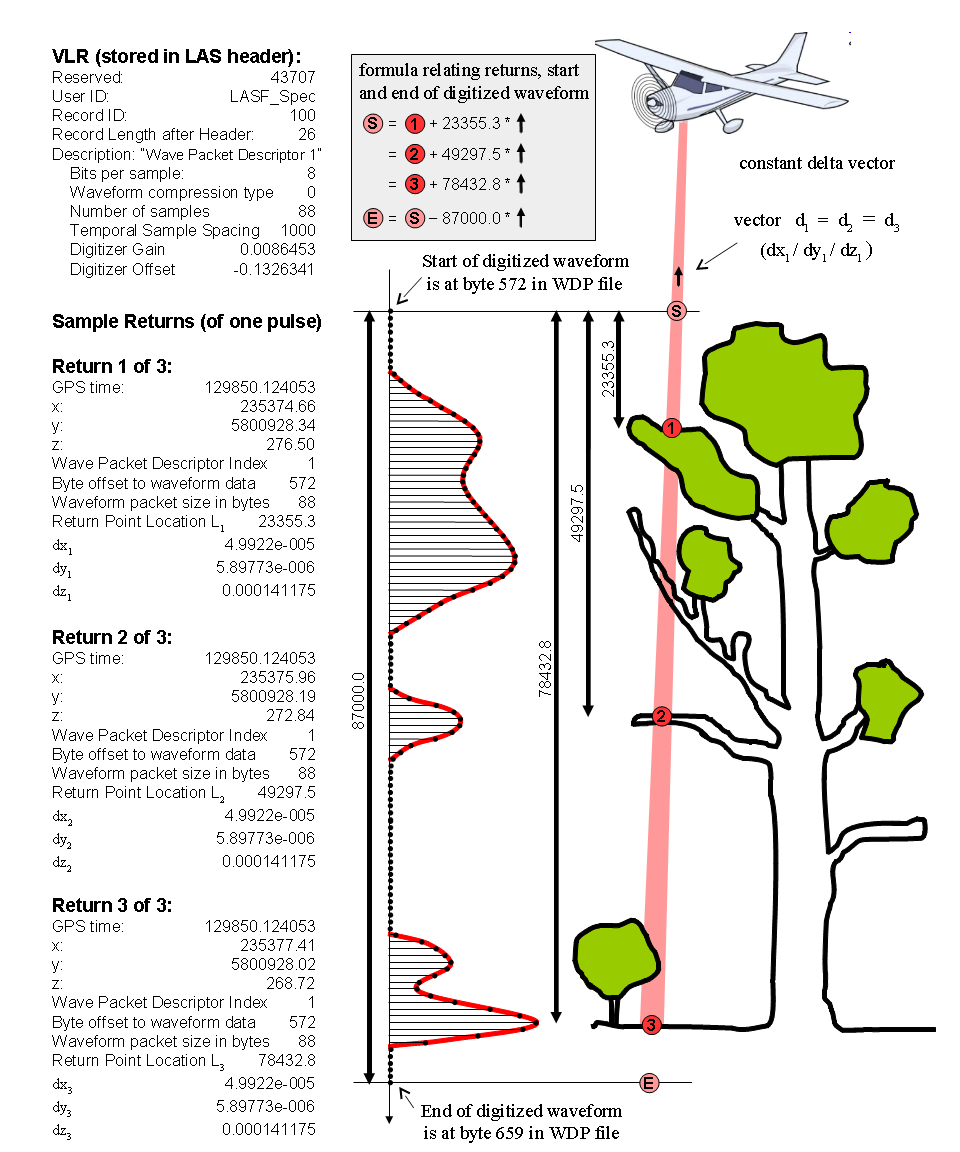
The local vectors of all returns of a pulse are identical if the laser light travels a straight line, which is a valid assumption for most topographic surveys. The illustration in Figure OLD (not attached) gives a simple example of how three different returns of a laser pulse relate to their digitized waveform.


However, in bathymetric surveys the laser beam gets refracted as it hits the water surface. Here the traversal of the sampled waveform needs to be done in segments. Traverse only in direction of the local vector from the first return to the first waveform samples, traverse in direction of the local vector from the second to the first return and no farther, traverse only in direction of the local vector from the third to the second return and no farther, ... etc. Only the traversal from the last return to the last waveform sample can go in the opposite direction of the local vector as illustrated in Figure NEW (attached).


The units of dx, dy, and dz are per picosecond and identical to the units of the  x, y, and z coordinates of the return.


LAS_FWF_illustration_bathy.png

Evon Silvia

unread,
Jul 14, 2015, 3:46:08 PM7/14/15
to last...@googlegroups.com, PulseWaves - no pulse left behind, las...@googlegroups.com
The latter clarification (breaking the waveform into segments) seems to assume that a water surface return was detected and digitized (i.e., there is a new anchor point), which frequently does not occur for bathymetric sensors in our experience. It seems to me that it would be up to the refraction software to break the waveform packet into two separate packets, with separate parametric equations and a new water surface anchor point defined, rather than the job of the specification.

I have always considered the identification of the "anchor point" for the parametric equations to be quite vague. If we're going through the effort to clarify the rest of the language, it would be helpful to have that also clarified. Is the anchor point for a particular packet the point that has been digitized, the first return of that pulse, or something else?

Evon

Martin Isenburg

unread,
Jul 27, 2015, 7:25:30 AM7/27/15
to LAStools - efficient command line tools for LIDAR processing, PulseWaves - no pulse left behind, las...@googlegroups.com
Hello Peter,

good point. I actually had it included in the graphic (note that the length of the vector in the water is shorter than the length of the vector in the air) but you are right it should also find its way into the text.

The speed of light in vacuum, commonly denoted c, is exactly 299,792,458 metres per second. The speed of light v at which light propagates through transparent materials such as air, water, or glass depends on the so the  refractive index n of the material (n = c / v). For example, for visible light the refractive index of glass is typically around 1.5, meaning that light in glass travels at c / 1.5 ≈ 200000 km/s; the refractive index of air for visible light is about 1.0003, so the speed of light in air is about 90 km/s slower than c. 

The speed of light v directly determines the length of the local direction and distance vector (dx/dy/dz) and this will slow as the laser goes from a thinner material (air) into denser material (water).

This should be added to the description.

Regards,

Martin @rapidlasso

On Tue, Jul 14, 2015 at 7:23 PM, Peter Guth <pg...@usna.edu> wrote:
>
> Hi Martin,
>
> In addition to bending in the water, the speed of light also changes, so the dx,dy, and dz will be different in water and air.  I don't see any indication of that in the  proposed description.
> --
> Peter L. Guth
> Professor, Dept Oceanography, USNA

Martin Isenburg

unread,
Jul 27, 2015, 7:39:51 AM7/27/15
to The LAS room - a friendly place to discuss specifications of the LAS format, last...@googlegroups.com, PulseWaves - no pulse left behind
Hello Evon,

I agree with you about the bathymetric data. I have personally not once seen a LAS 1.3 FWF file where all the bathy processing was done already (e.g. all water surface returns were detected, a water surface reconstructed, the refraction was calculated) and where appropriately bend and shortened vectors were output into the LAS FWF file for all returns below the water. So far the local direction and distance vector (dx/dy/dz) that I have seen have walways been identical for all returns. That is why my first illustration / description pair did not account for this fact.

However, Lewis quickly pointed out that my reformulated specification did no longer allow for this "intended" (?!?) use of the FWF extension. Hence I have now added a second illustration that shows this case too. Whether you make use of this or not is obviously up to the user. A quick check for identity of the local direction and distance vectors (dx/dy/dz) across all returns of a water pulse with a river or seabed return will immediately tell you if any such water surface correction has taken place for your particular LAS FWF delivery,

About your second concern ... this is *exactly* why I am in the process of suggesting to the ASPRS LAS Working Group (LWG) to add such illustrations. From these it becomes clear that each return is the anchor point for the waveform it references and that its location on the waveform is determined by the respective location value L that is part of the wavepacket information. I was hoping this is already clarified by the example, the equations, and the reformulation of the paragraph ... ? Is it not? Then please improve the formulation until we have one that can be understood uniquely ...  (-:

Martin

Evon Silvia

unread,
Jul 27, 2015, 12:07:25 PM7/27/15
to las...@googlegroups.com, last...@googlegroups.com, PulseWaves - no pulse left behind
Hello Martin,

Due to lack of demand, I haven't yet seen or attempted refraction of the waveform sample, partly because it seems to me that if the points are shifted slightly during calibration then it would follow that the parametric equation should also shift slightly. I've never seen that compensation occur, so it's quite a can of worms to open...

A second read of the specification and your graphic revealed that you did, in fact, graphically clarify the "anchor point" identity. In fact, the 1.4 specification's description of the "Return Point Location" for PDRF 4 is quite clear on what it means when it refers to "the associated return pulse". Simply changing that phrase to "this associated return pulse" (emphasis added here to clarify the change) and using it consistently throughout the waveform description should help with the clarity. That is, remove all references to an "anchor point" and instead refer to it as "this associated return pulse" every time so that it is clear that the exact same point is meant every time.

One clarification on your graphic... rather than use the "first" (F) and "last" (L) waveform sample, which could be confused with first and last return, perhaps use the nomenclature "start" and "end" of waveform sample?

Evon

Martin Isenburg

unread,
Jul 28, 2015, 8:52:40 AM7/28/15
to LAStools - efficient command line tools for LIDAR processing, las...@googlegroups.com, PulseWaves - no pulse left behind
Hello,

Evon, good idea to change "First" and "Last" waveform sample to "Start" and "End" of waveform sampling. I may adopt that also for PulseWaves. Any other suggestions to improve the new paragraph (see below) and the two illustrations (see attached) that I plan to suggest to add to the next (minor) revision of the LAS 1.4 specification?

===============


dx, dy, dz: A delta vector that specifies for the associated return the direction from where the laser light originated and the distance it traveled in picoseconds. Multiplying these delta vectors with p picoseconds and adding them to the position x,y,z of their corresponding return allows traversing the sampled waveform through space. The position P of the waveform p picoseconds before its return is given by:


   Px = x + p * dx

   Py = y + p * dy

   Pz = z + p * dz


The delta vectors of all returns of one pulse remain constant if the laser light travels a straight line, which is a valid assumption for most topographic surveys. The illustration in Figure CONSTANT (attached) gives a simple example of how three different returns of a laser pulse relate to their digitized waveform.


In a bathymetric survey the laser beam may get refracted when it hits the water surface and change both direction and speed. By storing changes in the delta vector with each return it is possible to store the result of a refraction calculation to the LAS file. In this case the traversal of the sampled waveform needs to be done in segments as illustrated in Figure CHANGING (attached):


* use the delta vector of the first return to traverse from the first return to the the start of the waveform sampling,

* use the delta vector of the second return to traverse from the second to the first return,

use the delta vector of the third return to traverse from the third to the second return,

* ...

* only the reversed delta vector of the last return to traverse from the last return to the end of the waveform sampling.


The units of dx, dy, and dz are per picosecond and identical to the units of the  x, y, and z coordinates of the return.


LAS_FWF_illustration_constant.png
LAS_FWF_illustration_changing.png

Evon Silvia

unread,
Jul 28, 2015, 1:05:34 PM7/28/15
to las...@googlegroups.com, LAStools - efficient command line tools for LIDAR processing, PulseWaves - no pulse left behind
Generally it looks good to me. I would clarify the last bullet as follows:
  • use the delta vector of the last return to traverse from the last return to the second-to-last return or in reverse to the end of the waveform sampling
That said, the graphics and language surprised me with the implied sign of dx/dy/dz. I would have expected the dx/dy/dz values to be positive along-pulse – i.e., from the origin (sensor) and toward the points. Is that not the case?

Evon

Martin Isenburg

unread,
Jul 29, 2015, 7:46:22 AM7/29/15
to The LAS room - a friendly place to discuss specifications of the LAS format, LAStools - efficient command line tools for LIDAR processing, PulseWaves - no pulse left behind
Hello,

okay. I will propose this to the ASPRS LAS Working Group (LWG).

Btw, Evon, I think you would make a great addition to the LWG. Maybe you can have Quantum Spatial Inc. officially apply to have you become a member? A large number of the current members are very very passive and don't ever participate in any of the technical or political discussions. It would be great to add another *active* member  in the LWG who has actual implementation and production experience with LAS readers and writers ... (-:

On Tue, Jul 28, 2015 at 6:50 PM, Evon Silvia <esi...@quantumspatial.com> wrote:
That said, the graphics and language surprised me with the implied sign of dx/dy/dz. I would have expected the dx/dy/dz values to be positive along-pulse – i.e., from the origin (sensor) and toward the points. Is that not the case?

I think you can read that from the wording of the old specification but it's not obvious. When I added full waveform support to "lasview" (press <SHIFT>-<W> or use the right-click pop-up menu) my only source of LAS FWF content was from Leica. Since they engineered the LAS FWF extension I figured that their file format got to be the "ground-truth". So here a bit of my personal LAS FWF history (some of it available via that link):


When RIEGL started exporting LAS FWF content in 2012 they did get exactly this wrong - they used a delta vector that was pointing away from the origin. Seemed a good idea to assure RIEGL's exports would be identical to the many and much ealier exported LAS FWF files by Leica so I when I visited them in June 2012 I started to worked with their engineers to modify the exporter. Later I learned that a (technicallly-skilled) client in Taiwan who had obtained an earlier large delivery of LAS FWF 1.3 files with inverted delta vectors wrote a custom tool to "invert" them back  ...

Later Trimble started exporting LAS FWF and got it wrong, then Optech started exported LAS FWF and got it wrong. I've worked with their engineers to match the original Leica (and then also RIEGL) convention of how to properly "attach" each full waveform sampling to their discrete returns. They are all fixed now.

The funny end of this story is that the latest Leica software "CloudPro" also got it wrong. They send me some test files that also had the delta vectors inverted. I concluded that if even the very company that originally wrote the spec gets it wrong when a different team of their own engineers uses said spec to reimplement a feature in a newer software ... then we need once-and-for-all fix the ambiguous wording of that spec and add a few illustrative examples. 

This is how this effort came about ... (-:

Regards,

Martin 

Martin Isenburg

unread,
Jul 30, 2015, 10:07:43 AM7/30/15
to The LAS room - a friendly place to discuss specifications of the LAS format, LAStools - efficient command line tools for LIDAR processing, PulseWaves - no pulse left behind
I have just proposed the following to the members of the ASPRS LAS Working Group (LWG):

===============================

Hello,

I am putting forward a motion to make a small revision of the current specification (LAS 1.4 r13) for more clarity in the specification of the FWF part. In particular this will add the two attached example illustrations (also available as PDF or SVG). These changes were discussed in these public forums:


============================

I propose the following change for clarity in the FWF part of the LAS 1.4 specification. This is because all 4 major vendors (RIEGL, Optech, Trimble, and Leica) had wrongly implemented their FWF exporters in their latest LAS 1.3 / LAS 1.4 writers due to miss-understanding the specification. The suggested change is relative to this LAS document here:

http://www.asprs.org/a/society/committees/standards/LAS_1_4_r13.pdf

=================

This is the original (page 14/15): 

Return Point location: The offset in picoseconds (10-12) from the first digitized value to the location within the waveform packet that the associated return pulse was detected.


X(t), Y(t), Z(t): These parameters define a parametric line equation for extrapolating points along the associated waveform. The position along the wave is given by:
   X = X0 + X(t)
   Y = Y0 + Y(t)
   Z = Z0 + Z(t)
where X, Y and Z are the spatial position of the derived point, X0, Y0, Z0 are the position of the “anchor” point (the X, Y, Z locations from this point’s data record) and t is the time, in picoseconds, relative to the anchor point (i.e. t = zero at the anchor point). The units of X, Y and Z are the units of the coordinate systems of the LAS data. If the coordinate system is geographic, the horizontal units are decimal degrees and the vertical units are meters.

===================

This is the proposed rewrite:

Return Point Location: The offset in picoseconds (10-12) from the start of the digitized waveform to the location (measured in time) within the digitized waveform that the corresponding return was detected.

dx, dy, dz: A delta vector that specifies for the associated return the direction from where the laser light originated and the distance it traveled in picoseconds. Multiplying these delta vectors with p picoseconds and adding them to the position x, y, z of the corresponding return allows traversing the digitized waveform samples through space. The position P_x, P_y, P_z of the waveform t picoseconds before its corresponding return is given by:

   P_x = x + t * dx
   P_y = y + t * dy
   P_z = z + t * dz

The delta vectors of all returns of one pulse remain constant if the laser light travels a straight line which is a valid assumption for most topographic surveys. The illustration in Figure 1 (attached) gives a simple example of how three different returns of a laser pulse relate to their digitized waveform.

In a bathymetric survey the laser beam may get refracted when it hits the water surface and change both direction and speed. By storing changes in the delta vector with each return it is possible to store the result of a refraction calculation to the LAS file. In this case the traversal of the digitized waveform needs to be done in segments as described below and as illustrated in Figure 2 (attached):

* use the delta vector of the first return to traverse from the first return to the the start of the digitized waveform,

* use the delta vector of the second return to traverse from the second to the first return,
* use the delta vector of the third return to traverse from the third to the second return,
* ...
* use the delta vector of the last return to traverse from the last return to the second-to-last return or in reverse to the end of the digitized waveform.

The units of dx, dy, and dz are per picosecond and identical to the units of the  x, y, and z coordinates of the return. The two illustrations in Figures 1 and 2 show the space-optimized case where a single digitized waveform is stored that is then referenced by all its returns. It is also possible to store a separate digitized waveform for each return, either by storing the exact same digitized waveform multiple times or by storing only the section of the digitized waveform that is relevant for the corresponding return.

==================

Obviously the corresponding entries in Tables 13, 14, 20, and 21 also have to be changed from x(t), y(t), z(t) to dx, dy, dz.

Regards,

Martin
figure1_LAS_FWF_illustration_constant.png
figure2_LAS_FWF_illustration_changing.png

Evon Silvia

unread,
Feb 23, 2018, 6:50:26 PM2/23/18
to The LAS room - a friendly place to discuss the LAS and LAZ formats
Hello all,

I've created an issue on the new ASPRSorg LAS GitHub page to house further discussion on this topic: https://github.com/ASPRSorg/LAS/issues/9

Several of these wording changes will be incorporated into the R14 release. The graphics, however, and most of the explanation I've just incorporated into the very first LAS wiki page here: https://github.com/ASPRSorg/LAS/wiki/Waveform-Data-Packet-Descriptors-Explained

If you have a few minutes, I'd appreciate it if you reviewed the explanations and examples there and post any comments to the Issue page.

Evon
Reply all
Reply to author
Forward
0 new messages