INFO: Milight - wireline bridge
2,520 views
Skip to first unread message

leutholl
May 30, 2014, 7:17:50 PM5/30/14
to ope...@googlegroups.com
Hi
I tried various bridges from Futlight (the manufactor for milight, limitlessbulb etc....). V4 claims to have Wifi n support and auto-reconnect - it also can send channels that are higher than 6 to support the RGBW (and the groups) that V3 can't do. No matter how deep I dive into configuration I can't make V4 reliable on my network. ping response is good when it boots but after around 140 seconds I get a lot of dropouts that seems to be occuring from the node itself and not due to bad wifi / RF conditions (RSSI, channels, 5GHz on the same SSID...). As an icing on the cake, they even removed the admin web gui on the bridge which allowed us the configure static ip and various other settings that are present on the V3 bridge. I even found the original firmware of the wifi chip/module used on the V4 bridge and flashed that. Result: web gui comes back allowing static ip and various other things but longterm network accessibility is still bad and I overwrote the application coming from futlight which supported the ios remote and configuration that speaks to the wifi module by sending AT+ commands (Hayes commands) on port 48899 rather on the UDP user port 8899. I tried pretty much everything but couldn't get it better! So I gave up and decided to reverse-engineer the bridge. After a quick mail to futlight if they would plan for some wireline bridge (which they neglected saying: "We are a wireless company...") I started my work and this is what I found:
The bridge (V3 and V4) consist of two sides:
A) A Wifi module that accepts udp packets on a configurable ports and passes the bytes transparently(!) to a UART port - very similar to RS232 but with 3.3V. It is a send only device - in fact the RxD isn't even connected ;-) - This Wifi module has the web gui (which futlight removed/disabled by flashing a so called application which does some other kind of configuration as well). It is a general purpose Wifi to serial module and it could even support TCP server and TCP client - along comes a impressive documentation of AT+ commands - but still, I got problems on my wifi. Note that this module also drives all the LEDs using the GPIO.
B) A 2.4GHz transceiver with MISO/MOSI interface that will frame the message can drive the antenna and manages medium access. That's again a general purpose 2.4GHz transceiver which could(!) receive but the register's content on the bridge are set to send-only and this is even reflected on the pcb layout which is uni-directional.
Needless to say what to try next: Hook up my logic analyzer in the middle of the two modules and sniff the messages to see if there are any other bytes that don't belong to the message. -> result: 1:1 transparent without any injected additional bytes. So that got me hooked up!
If there would only be a wireline UDP->serial module which would pass the message transparently - I could replace the weak wifi module with this module and get 100% reliable networking, heck even more features. This reminded me of a DMX4All converter that I opened the other day just to find that in fact this is similar built: a Lantronix XPort (RJ45, 100 Mbps) module (basically the chipset is in the RJ45 enclosure) that drives a ATMEL AMR using serial lines. The AMR then creates the DMX frames. A small circuit balances it to RS482. So I decided to use the Lantronix XPort of this module since the configuration capability is really amazing. Pretty much every aspect of networking, serial, frame-ing etc... can be set. It even supports telnet, snmp, echo, web, 5 different ways how to react on udp or tcp, it could even listen to a byte pattern and send emails ;-).... Well, I took this module out of the board - reconfigured it to port 8899, set some LAN configuration and serial parameters, checked the correct udp behaviour to make it really transparent. Then I sniffed the serial out once again to check if that should work when directly hooked up with the 2.4 Ghz transceiver. Due to the amazing configuration-abilty I got the very same bytes on the serial out that I send using netcat (or using openhab). A quick check and: et voila - it works! ;-)
Some additional work for power supply (3.3V, 5V etc...) - enclosure/box and a cable to separate the two "sides" of my bridge so I can position the 2.4 Ghz part (which is back in the original china junk box which now has a cable with the serial and power supply) somewhere with good RF condition (I do have 30+ futlight lamps) and keep the networking side (the Xport) near my switch.
So my new bridge works perfectly for all milight products and I do have amazing ping response (no dropouts, no long latency) - it never sleeps due to power mode (which is my assumption why the wifi module used on the original V4 bridge is so loose on ping after a period - not that the V3 bridge didn't do that but has other problems.)
If you are interested I can share the documentation and some photos I collected along this work. As for me I keep my bridge wired, I don't like the wifi modules coming from china ;-)
Hope that encourages somebody to do the same - I'm sure the XPort are available on ebay and shouldn't be too expensive - the rest is really easy to do ;-)
PS: futlight is an excellent manufacture and seller - ordering a huge quantity of the products and sending them to my place, professional on money transfer, customs declaration, track'n'trace, shipping carrier selection, boxing etc... and I can tell you it is DIRT CHEAP! Order the lamps directly from them - just don't use the wifi bridge ;-)
leutholl

PeterD
Jun 1, 2014, 12:25:23 AM6/1/14
to ope...@googlegroups.com
On Friday, May 30, 2014 4:17:50 PM UTC-7, leutholl wrote:
I tried various bridges from Futlight [...] I tried pretty much everything but couldn't get it better! So I gave up and decided to reverse-engineer the bridge [...] and this is what I found:
[...] I could replace the weak wifi module with [a Lantronix XPort] module and get 100% reliable networking, heck even more features. [...]If you are interested I can share the documentation and some photos I collected along this work. [...]
Hi leutholl -
Just wanted to say thanks for sharing this. I find myself frustrated at how many devices which want to become a part of the infrastructure of our home networks offer only WiFi...
Please do post the additional info & photos, as I'm sure I won't be the only person interested in hacking their Milight bridge and would love some more "how-to" details.
Cheers,
Peter

Sebastien Baguet
Jun 1, 2014, 1:20:16 PM6/1/14
to ope...@googlegroups.com
Hi leutholl,
Thanks for sharing this. i'm a new user of milight bulbs + openhab. I got no problem so far with the wifi part but i think that a wired bridge is a really better option.
Feel free to share pics and info about this. Maybe i will try to do the same...
I should also be interested in reverse-engineer the RF protocol to be able to control as many device as possible with only one controller (and not only 4 groups with the current bridge). I think i will try to disassemble my bridge on next week ;-).
--
Seebag
Lukas Leuthold
Jun 1, 2014, 2:15:14 PM6/1/14
to ope...@googlegroups.com
OK - Thanks!
I do have to make another wireline bridge for another room. I will try to put together a small doc set. Maybe a short video. I will also source the components on ebay or somewhere that you guys can get it cheap. If anybody is into PCB layout - we could even start a small serie. The bridge from futlight is around 10$, the XPort porbably around 30$ so that should lead us into a price of around 60-70$ which I will pay without a doubt if my milights are reliable (think of it as the price of one philips hue bulb)
The RF protocol is not the problem - I'm pretty sure it's transparent and has nothing to do with channels or groups etc... I think the limitation lies in the "firmware" in the bulb itself - it will just listen for the commands (3 bytes) the product was designed for - so unless futlight will come up with new bulbs that "listen" to higher channels, we are all limited to 4 groups for CW/WW, 1 group for RGB and 4 groups for RGBW. A newer version of CW/WW downlight would be nice anyway since brightness and colortone can't be set absolutely but relative. this makes the logic in the rules a bit harder to implement. Technically, Philips Hue is a product that convinces me the most, but comes with its price tag. But Philips GU11 blulbs are really outstanding! Interestingly, the cheapest price is on Apple Store other retailers (if any) are higher.
But what you can do is to make more bridges and pair some bulbs to the 2nd bridge and some of them additionally to the 1st bridge (which is possible). So that get's you more groups. Openhab is already prepared for two bridge ID's.
thanks.
--
You received this message because you are subscribed to a topic in the Google Groups "openhab" group.
To unsubscribe from this topic, visit https://groups.google.com/d/topic/openhab/ayFUwuABpcE/unsubscribe.
To unsubscribe from this group and all its topics, send an email to openhab+u...@googlegroups.com.
To post to this group, send email to ope...@googlegroups.com.
Visit this group at http://groups.google.com/group/openhab.
For more options, visit https://groups.google.com/d/optout.

Kai Kreuzer
Jun 1, 2014, 2:52:27 PM6/1/14
to ope...@googlegroups.com
Hi leutholl,
Thanks for sharing this, pretty cool! You should think about producing and selling these wired gateways :-)
Do you also use RGB strip controllers with this solution? It could indeed be a good value solution to use all over the house (while things like Philips Hue are deadly expensive in comparison).
Best regards,
Kai
--
You received this message because you are subscribed to the Google Groups "openhab" group.
To unsubscribe from this group and stop receiving emails from it, send an email to openhab+u...@googlegroups.com.
Lukas Leuthold
Jun 1, 2014, 4:11:13 PM6/1/14
to ope...@googlegroups.com
yes there is a RGB strip that I can control - but I think I got an older version of the controller (milight) which is RGB + White and the White is only controllable by setting the disco mode (thanks to openhab rules I can set the white and the colors independantly which is not possible with the original remote - this gives a very nice "wash" kind of color for mood and ambient (mix a color with white) - Don't remember where I got the strip itself, as I asked Futlight - they don't sell any - I think it's this one:
http://www.alibaba.com/product-detail/DC24V-controllable-Led-rgbw-strip-14_737834361.html
(very dense leds per metre and I'm pretty shure it's dirt cheap).
I have to order the newer controller which should act as a RGBW bulb (although it is not a bulb but listens to the same commands) - I should be able to set each color independantly which going through rules. But I shall try first.
Quality of light wise - Philips is really superior. Especially the white color tones. Milight color range/room/gamut isn't nearly as close as Philips - but then, we just have to illuminate the room so we can accept a lower resolution in steps. Will try to get together my HOWTO and the products I used so far when I have to make a 2nd wireline bridge (in about a month)
I will keep you posted what's going on here.
leutholl
You received this message because you are subscribed to a topic in the Google Groups "openhab" group.
To unsubscribe from this topic, visit https://groups.google.com/d/topic/openhab/ayFUwuABpcE/unsubscribe.
To unsubscribe from this group and all its topics, send an email to openhab+u...@googlegroups.com.
Sebastien Baguet
Jun 1, 2014, 4:27:59 PM6/1/14
to ope...@googlegroups.com
On Sunday, June 1, 2014 8:15:14 PM UTC+2, leutholl wrote:
I do have to make another wireline bridge for another room. I will try to put together a small doc set. Maybe a short video. I will also source the components on ebay or somewhere that you guys can get it cheap. If anybody is into PCB layout - we could even start a small serie. The bridge from futlight is around 10$, the XPort porbably around 30$ so that should lead us into a price of around 60-70$ which I will pay without a doubt if my milights are reliable (think of it as the price of one philips hue bulb)
Ok, good ! Xport seems a little bit over sized for this but is easy to setup.
For a new PCB, a small avr with an enc28j60 could do the job (i use microduino open hardware products to prototype with these).
The RF protocol is not the problem - I'm pretty sure it's transparent and has nothing to do with channels or groups etc... I think the limitation lies in the "firmware" in the bulb itself - it will just listen for the commands (3 bytes) the product was designed for - so unless futlight will come up with new bulbs that "listen" to higher channels, we are all limited to 4 groups for CW/WW, 1 group for RGB and 4 groups for RGBW..
As many bridges can be used to control 4 groups each, the bridge id seems to be used in the RF protocol. Maybe it could be possible to send special command to the RF chip (pl1667) to send another bridge id....? I tried to download component datasheet from pmicro, but it's only a product presentation.
I will try to get more information on these chips.
A newer version of CW/WW downlight would be nice anyway since brightness and colortone can't be set absolutely but relative. this makes the logic in the rules a bit harder to implement.
Yes it's a big problem !
I'm working to improve milight binding on these context things, i will post my work once done.
Technically, Philips Hue is a product that convinces me the most, but comes with its price tag. But Philips GU11 blulbs are really outstanding! Interestingly, the cheapest price is on Apple Store other retailers (if any) are higher.
I though GU11 bulbs were not remote controlled ?
Lukas Leuthold
Jun 1, 2014, 4:41:54 PM6/1/14
to ope...@googlegroups.com
Thanks!
The XPort is an overkill, yes - but I like to have access to every aspect of TCP/IP control (incl. MTU size, SNMP for monitoring etc...) - Will try to get one with a small board so prototyping is easier... Prototyp 1 is with a cable that will connect this XPort-Board with the Milight bridge (without the Wifi) - it should be better using a Raspberry Pi and use the UART (heck, even USB_to_serial would work) and interface to the PL1176 directly.
The reason why I still use the bridge is because of the pre-programmed PL1167 - you are right, the 2.4GHz transceiver sends his "id" along (that's why pairing with multiple remotes/bridge on different channels work). So they are preset registers to make it work with the bulbs. It's not that transparent than I thought.
The Milight bridge is that dirt cheap that it's even worth it to use one be it for the PL1167 alone. Getting rid of the Wifi-daugtherboard is simple as 1-2-3 and there is even a 3.3V regulator onboard and some leds that are useful for our own bridge.
So Prototyp 2 will be one with the split bridge of Milight but then using a USB-to-serial which can either be plugged in at a raspberry (to function as a UDP to USB-serial bridge) or directly to the machine where openhab runs.
I do have a question: How can I set the white color/channel independantly of the RGB color/channel with openhab milight binding? which sitemap object would work best?
PS: There are Philips Hue GU10 (my bad it's GU10 and not GU11) - that are outstanding in quality! It's a dream of a light, but you know about the price tag...
Thanks!
Lukas
Sebastien Baguet
Jun 1, 2014, 5:22:23 PM6/1/14
to ope...@googlegroups.com
On Sunday, June 1, 2014 10:41:54 PM UTC+2, leutholl wrote:
Thanks!The XPort is an overkill, yes - but I like to have access to every aspect of TCP/IP control (incl. MTU size, SNMP for monitoring etc...) - Will try to get one with a small board so prototyping is easier... Prototyp 1 is with a cable that will connect this XPort-Board with the Milight bridge (without the Wifi) - it should be better using a Raspberry Pi and use the UART (heck, even USB_to_serial would work) and interface to the PL1176 directly.The reason why I still use the bridge is because of the pre-programmed PL1167 - you are right, the 2.4GHz transceiver sends his "id" along (that's why pairing with multiple remotes/bridge on different channels work). So they are preset registers to make it work with the bulbs. It's not that transparent than I thought.The Milight bridge is that dirt cheap that it's even worth it to use one be it for the PL1167 alone. Getting rid of the Wifi-daugtherboard is simple as 1-2-3 and there is even a 3.3V regulator onboard and some leds that are useful for our own bridge.So Prototyp 2 will be one with the split bridge of Milight but then using a USB-to-serial which can either be plugged in at a raspberry (to function as a UDP to USB-serial bridge) or directly to the machine where openhab runs.
Cool !
Prototyp 2 seems easy to do, we could use the USB port present on the bridge to take out D+ and D-.
Do you have v4 or v3 bridge ?
I do have a question: How can I set the white color/channel independantly of the RGB color/channel with openhab milight binding? which sitemap object would work best?
Maybe i don't understand you question :
1. RGBW bulbs have RGB mode or White mode. You cannot set both mode at the same time.
2. Regarding sitemaps, with the current binding version there is no way to declare only one item/sitemap object to control RGB + White mode
You should at least use 2 items + 2 sitemaps (1 switch + 1 colorpicker for instance)
As i'm working on the binding, I will try to see if it could be possible to receive ON command on the colorpicker (when you clic on the up arrow of the colorpicker) to switch on white mode.
One other way should be to switch to white mode when you click on the center of the color wheel (with some threshold).
What do you think about the last option ?

gleks...@gmail.com
Sep 30, 2014, 3:38:19 PM9/30/14
to ope...@googlegroups.com
Can you help me to build it to?
Dne sobota, 31. maj 2014 01:17:50 UTC+2 je oseba leutholl napisala:
Dne sobota, 31. maj 2014 01:17:50 UTC+2 je oseba leutholl napisala:
Lukas Leuthold
Sep 30, 2014, 4:19:02 PM9/30/14
to ope...@googlegroups.com
I'm behind schedule to write an instruction. Before I catch up, how can I help you? You need a UDP->serial (0V - 3.3V) converter and then split the V4 bridge you have - the rest is easy when you are a tinkerman....
Gregor Lekse
Oct 1, 2014, 1:24:29 AM10/1/14
to ope...@googlegroups.com
I have milight v4.0 bridge which controls led strips. 4 groups BW and four groups rgbw. I don't like wifi I whoud like to control it with wire. Is that possible?
Dne 30. sep. 2014 22:19 je oseba "Lukas Leuthold" <leut...@gmail.com> napisala:

tomfr...@gmail.com
Nov 15, 2014, 8:00:44 AM11/15/14
to ope...@googlegroups.com, gleks...@gmail.com
Hi All,
Op woensdag 1 oktober 2014 07:24:29 UTC+2 schreef Gregor Lekse:
Just came by this topic! Interesting stuff! I just received my wifi controller and immediately took it apart!
As pointed out there is a wifi board that sends commands to the 2.4Ghz transceiver.
My original idea for this module was to see how it works and maybe rewire it to a raspberry or arduino. That way I was hoping to get rid of the 4-zone limitation because I have complete control of sending 2.4Ghz commands... From what I read this might be a bit more complicated then expected :P
Any ideas what the other IC is on the board? I guess some kind of microcontroller? Labelling has been removed, so no idea what it is.
Op woensdag 1 oktober 2014 07:24:29 UTC+2 schreef Gregor Lekse:
Sebastien Baguet
Nov 16, 2014, 3:24:09 PM11/16/14
to ope...@googlegroups.com, gleks...@gmail.com, tomfr...@gmail.com
Hi Tom,
There is two chips on the board. One is the wifi to serial controller, the other is a pl1667 from pmicro, a 2.4GHz tranceiver. I tried to contact pmicro to get the datasheet of this chips with no success.
The commands sent by wifi are directly transfered to the pl1667 chip via serial port with no transformation.
All the four channels seems to be handled by this chip.
Lukas Leuthold
Nov 17, 2014, 5:08:36 AM11/17/14
to ope...@googlegroups.com, gleks...@gmail.com, tomfr...@gmail.com
it's easy to do, you can split the controller in two half and send serial to the RF chip. the other half is just an UDP to serial (ttl with 2 wires tx only, 3.3V). I've found a cheap ethernet to serial bricklet which does the job. I'm looking for a PoE version...

chri...@greatescape.de
Nov 22, 2014, 2:27:09 PM11/22/14
to ope...@googlegroups.com
Hi Leutholl,
could you share the pinout to connect to the Lantronix XPort ?
Thanks in advance,
Chrisotph
could you share the pinout to connect to the Lantronix XPort ?
Thanks in advance,
Chrisotph
Lukas Leuthold
Nov 22, 2014, 6:53:07 PM11/22/14
to ope...@googlegroups.com
Yes. Here is the info:
Wlan module of original milight bridge pinout:
10
9
8
7
6 RxD
5 TxD
4
3
2
1 GND
XPort Pinout:
Pin 4 and Pin 5
XPort Settings (important is Datagramm Type 01 with the Remote Host (I use my gateway ip address to be free with the ip-address of openhab):

Anh-Kiet Ngo
Jan 27, 2015, 4:39:41 AM1/27/15
to ope...@googlegroups.com, gleks...@gmail.com, tomfr...@gmail.com
Hey leutholl,
Were you able to find a PoE version? If not, could you point me to the one you found?
I am completely new to this, but I would like to be able to go straight ethernet as well. I was able to get one to work with this guide, http://servernetworktech.com/2014/09/limitlessled-wifi-bridge-4-0-conversion-raspberry-pi/, but it'll be much cheaper to go with an ethernet to serial module.
Since I really don't know what I'm doing, is it correct that if I connect the RxD of the ethernet-to-serial to the existing RxD that it should essentially be a drop-in replacement?
Thanks for the writeup so far!
-ak
Anh-Kiet Ngo
Jan 27, 2015, 4:54:19 AM1/27/15
to ope...@googlegroups.com, gleks...@gmail.com, tomfr...@gmail.com
One more thing to note.
I found these, http://www.stiplight.com/handleiding.pdf, which appears to be a rebranded version of Marlight, which from everything I can tell, is just Milight underneath. I am not 100% sure though. The nice thing is that it comes with an ethernet port and the documentation indicates that it can control up to 16 groups. Maybe they just squeezed 3 more transceivers into that big box?
Can anyone confirm/reject this?
Lukas Leuthold
Jan 27, 2015, 9:06:41 AM1/27/15
to ope...@googlegroups.com, gleks...@gmail.com, tomfr...@gmail.com
do you have this bridge? if yes, have a look inside to see if you can find the RF chip. It will most probaby just what I did, but less tinkering.
I contacted some manufactors that sell Ethernet to TTL chipsets but albeit they once used to sell PoE devices, they all seem to cancel this product line. I guess, PoE isn't that easy to build in terms of MTBF as it's running of 48V and quite some logic involved, after this there must be step-down converter to get to our 3.3V.
I'll check again if I can find a XPort alternative.
But basically, yes this is how it works :-)
To view this discussion on the web visit https://groups.google.com/d/msgid/openhab/99fc775a-10fe-44c7-8387-48e905df1a44%40googlegroups.com.
Anh-Kiet Ngo
Jan 27, 2015, 2:51:50 PM1/27/15
to ope...@googlegroups.com, gleks...@gmail.com, tomfr...@gmail.com
Sadly I do not have the bridge and what I posted is just pure speculation. I was hoping that someone else with it would be able to chime in.
To view this discussion on the web visit https://groups.google.com/d/msgid/openhab/8F60B959-A323-4CB0-B1CD-42CD7CF5A847%40gmail.com.
Anh-Kiet Ngo
Jan 27, 2015, 10:36:19 PM1/27/15
to ope...@googlegroups.com
Sebastien,
If you are still looking into this, the cursory research I've done shows that the PL1167 is supposed to be compatible with the LT8900, which the datasheet can be found here, http://www.datasheet-pdf.com/datasheetdownload.php?id=769989.
Now, let me preface that I have no idea on what any of this means.
I've looked at the SPI formats and they appear to be similar with the PL1167 document, http://www.szkexinda.com/Upload/PicFiles/2014.2.8_9.21.48_1259.pdf. I don't know what SPI formats are, but it sounds important :).
Another thing I noticed on page 24, it indicates that registers 36-39 can be used to "choose unique sync words for each over-the-air network. Similar to a MAC address." Then page 26 says that this is part of the packet data structure. Even the preamble is programmable. With my total experience of about an hour looking at this stuff, it seems possible to be able to read these registers and modify them as necessary to create a unique id on the fly.
As far how to do any of this stuff is complete voodoo to me.
Sebastien Baguet
Jan 28, 2015, 6:31:14 PM1/28/15
to ope...@googlegroups.com
It's seems interesting.
I will take a closer look to see if it's possible to read or program these registers.
Thanks.

leutholl
Mar 15, 2015, 10:12:43 AM3/15/15
to ope...@googlegroups.com
Features:
- stable WiFi bgn
- two Ethernet ports - LAN and WAN (I'm using the WAN port, however the operation mode allows different setups such as WiFi to Ethernet, DHCP with NAT on LAN etc... - this board is basically a router, quite a strong one actually.)
- RS232 (+12V) - can also be used
- 3.3V UART
- Power supply included but can be powered by USB as well
- cost: any milight bridge plus 27$
Approach:
1) get this "jack-of-all-trade" board from dx.com: click here
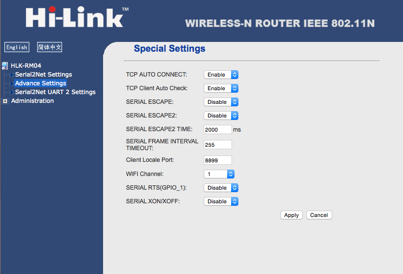
2) configure the board using it's WAN port (DHCP) then login on the web frontend with admin/admin and change according to your needs. Some settings must be as shown in the picture
2) chop the milight bridge in half - get rid of the WIFI module as we did in the first version (and many others)
3) solder three wires as shown in the picture: +5V, GND, TxD (3.3V UART) - I chose to run it over 5V to allow both connectors as a power source (power supply of the VRM04 or USB of the milight bridge (don't use both at the same time) - since both voltage regulator are close and the IO pins are inverted with pull-ups on the bridge side, meaning the UART TxD can be low impedance, this shouldn't lead to any problems although we're interfacing with 3.3V but powering it with 5V.
4) pair some lights and test it with netcat. For the white downlights be command set is different - see all commands here
echo -ne "\x38\x00\x55" | nc -u -p8899 -w0 {bridge ip} 8899
echo -ne "\x3B\x00\x55" | nc -u -p8899 -w0 {bridge ip} 8899
Note the pairing is sticky to the remote (or in our case the bridge) meaning that although the commands are all the same, the light knows from the pairing procedure which remote to listen to.
5) mount the VRM04 on the backside of the original milight bridge case as shown in the picture.
6) voila: you have a "can-do-allthings" bridge for a total price of about 40$. I personally prefer this over a raspberry.


Reply all
Reply to author
Forward
0 new messages